1
Lab 1. Basic Electronic Instruments and Measurements
Object. In this assignment we learn to work with power supplies, voltmeters, ammeters, and ohmmeters. We
shall measure the V-I characteristic for a resistor, and the transfer characteristic for a TTL and a CMOS inverter.
We set up an LED voltage level indicator for CMOS chips. This lab should be completed in a session (1 week).
Power Supply. This supplies electrical power at a specified voltage across its terminals. This voltage may be
fixed or variable. For example the Tektronix PS503A on your bench has one pair of output terminals which
supplies power at 5-Volt and another pair whose output voltage can be adjusted between 0 and 20 Volts. The
PMC power supply is another voltage power supply available on our work bench.
Voltmeter. A voltmeter measures the voltage drop from the point to which its red terminal is connected to the
point to which its black terminal is connected. Tektronix DM502 digital multimeter can be used as a voltmeter with
the appropriate control buttons depressed. Suppose a voltmeter measures x Volts when connected across
points A and B. If we interchange the leads from the voltmeter which are connected to A and B then it will
measure -x Volts.
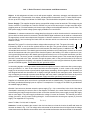
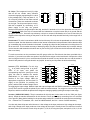
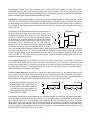
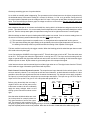
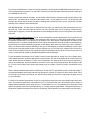
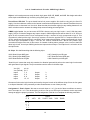
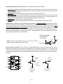
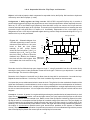
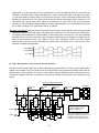
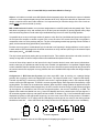
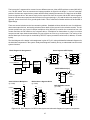
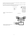
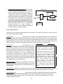
Ground. The "ground" in a circuit provides a voltage reference point at 0 Volt. The ground is usually
indicated by “GND” or one of the two symbols shown on the right. The ground terminal is usually
color-coded black. In some instruments there is a third terminal, the chassis ground, in addition to the
red and the black terminals. The chassis-ground terminal (sometimes color-coded green) connects to the metal
case of the instrument and to the ground of the electrical system in the building. Your have an option to tie your
circuit ground (black terminal) to the chassis ground (green terminal) or not. In some other instruments you don’t
have this option. The circuit ground is internally connected to the chassis ground. This means that the ground
terminal is connected to the case, and also, through the power cable, to the ground terminal of all electrical
power being supplied to the building. It is important to realize that if you are using such devices all points marked
ground are shorted together. There can be only one ground in a circuit.
In connecting together various grounded instruments and supplies we have to make sure that a power supply
never gets shorted, i.e., have its two output terminals connected together. In such a case we are asking the
supply for an enormous amount of power which might destroy something. All the supplies in the laboratory are
well designed and will turn themselves off or display a red light should such a contingency arise. However this
may not happen soon enough to prevent some damage, and in any case it is bad practice to have to rely on this
safety measure. The two output terminals of a power supp ly must never get directly connected together.
Supplies or instruments which do not have a grounded terminal are called floating. The same instrument may
have both grounded and floating inputs or outputs. For example the 5-V supply on the PS502 is grounded and
the variable supply is floating.
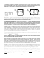
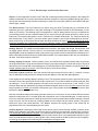
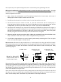
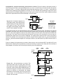
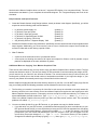
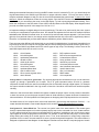
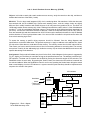
Circuit. If we connect an element across the power supply (Fig. 1-1a) a current flows in the circuit. Note that a
closed path is necessary for current to flow. In the diagram, for instance, the current flows from the supply to the
element along the lead, through the element, back to the other terminal of the power supply, through the supply
and so round again. The power supply maintains the voltage V across its terminals. The element now has a
voltage V across it, and a current I flowing through it. In this situation the element gets a power (P) from the
supply. The magnitude of P is given by:
P = V × I,
where P in Watt, V in Volt, and I in Ampere.
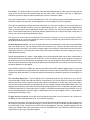
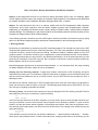
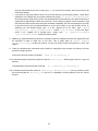
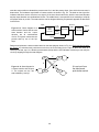
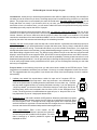
Ammeter. In order to measure the current in the circuit we have to cut into the circuit at A and B and insert the
ammeter as shown in Fig. 1-1b. The voltage at the red terminal of the ammeter has to be higher than the voltage
at the black terminal so that the current enters at the red terminal and leaves at the black terminal. If the ammeter
4