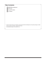
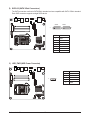
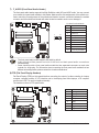
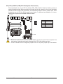
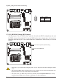
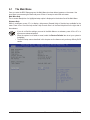
1
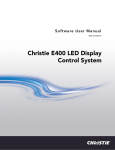
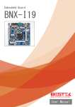
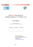
MSH61DI LGA1155 socket motherboard for Intel® Core™ i3 / Core™ i5 Core™ i7 processors/ Intel® Pentium® series processors User's Manual Rev. 1001 Copyright © 2011 GIGA-BYTE TECHNOLOGY CO., LTD. All rights reserved. The trademarks mentioned in this manual are legally registered to their respective owners. Disclaimer Information in this manual is protected by copyright laws and is the property of GIGABYTE. Changes to the specifications and features in this manual may be made by GIGABYTE without prior notice. No part of this manual may be reproduced, copied, translated, transmitted, or published in any form or by any means without GIGABYTE's prior written permission. Documentation Classifications In order to assist in the use of this product, GIGABYTE provides the following types of documentations: For quick set-up of the product, read the Quick Installation Guide included with the product. For detailed product information, carefully read the User's Manual. For product-related information, check on our website at: http://www.gigabyte.com Table of Contents Box Contents....................................................................................................................4 MSH61DI Motherboard Layout.........................................................................................5 Chapter 1 Hardware Installation......................................................................................7 1-1 1-2 1-3 Installation Precautions..................................................................................... 7 Product Specifications....................................................................................... 8 Installing the CPU and CPU Cooler................................................................ 10 1-3-1 1-3-2 1-4 Installing the Memory...................................................................................... 13 1-4-1 1-4-2 1-5 1-6 Installing the CPU....................................................................................................10 Installing the CPU Cooler........................................................................................12 Dual Channel Memory Configuration......................................................................13 Installing a Memory ................................................................................................14 Back Panel Connectors................................................................................... 15 Internal Connectors......................................................................................... 17 Chapter 2 BIOS Setup...................................................................................................27 2-1 2-2 The Main Menu............................................................................................... 29 Advanced Menu.............................................................................................. 31 2-2-1 2-2-2 2-2-3 2-2-4 2-2-5 2-2-6 2-3 2-4 2-5 2-6 ACPI Settings..........................................................................................................32 CPU Configuration...................................................................................................33 SATA Configuration.................................................................................................35 Intel TXT(LT) Configuration.....................................................................................37 USB Configuration...................................................................................................38 H/W Monitor.............................................................................................................40 Chipset Menu.................................................................................................. 41 Boot Menu....................................................................................................... 43 Security Menu................................................................................................. 44 Exit Menu........................................................................................................ 45 -3- Box Contents MSH61DI motherboard Driver CD Two SATA cables I/O Shield • The box contents above are for reference only and the actual items shall depend on the product package you obtain. The box contents are subject to change without notice. • The motherboard image is for reference only. -4- MSH61DI Motherboard Layout 1 2 3 4 5 6 7 8 9 10 11 28 27 12 26 29 30 13 25 14 24 15 16 17 18 23 22 -5- 21 20 19 Item 1 2 3 4 5 6 7 8 9 10 11 12 13 14 15 16 17 18 19 20 21 22 23 24 25 26 27 28 29 30 Code SPEK LINE_IN SPDIF R_USB2 R_USB1 BAT HDMI CLR_CMOSHW LAN1 DC_IN ATX_19V MIN_PCIE1 M_SATA TP_USB TV_USB BL_SW F_PANEL SATA1/SATA2 HDD_PWR F_USB1 F_AUDIO1 CPU_FAN CPU1 SYS_FAN FPD LVDS DMIC_CON WEB_CON SODIMMB1 SODIMMA1 Description Speaker cable connector Audio Line In port Optical S/PDIF Out connector USB 3.0 ports USB 2.0 ports Battery connector HDMI port Clear CMOS jumper RJ45 LAN port DC In power connector 2 pin power connector Mini PCi Express connector MSATA connector Touch panel USB connector TV tuner USB connector Back Light switch Front panelconnector SATA cable connectors Hard disk power connector USB connector Audio cable connector CPU fan connector Intel LGA1155 socket System fan connector Flat Panel Display connector LVDS connector Digital Mic connector WEBCAM connector DDR3 SO-DIMM slot (channel B-1 ) DDR3 SO-DIMM slot (channel A-1 ) -6- Chapter 1 Hardware Installation 1-1 Installation Precautions The motherboard contains numerous delicate electronic circuits and components which can become damaged as a result of electrostatic discharge (ESD). Prior to installation, carefully read the user's manual and follow these procedures: • Prior to installation, do not remove or break motherboard S/N (Serial Number) sticker or warranty sticker provided by your dealer. These stickers are required for warranty validation. • Always remove the AC power by unplugging the power cord from the power outlet before installing or removing the motherboard or other hardware components. • When connecting hardware components to the internal connectors on the motherboard, make sure they are connected tightly and securely. • When handling the motherboard, avoid touching any metal leads or connectors. • It is best to wear an electrostatic discharge (ESD) wrist strap when handling electronic components such as a motherboard, CPU or memory. If you do not have an ESD wrist strap, keep your hands dry and first touch a metal object to eliminate static electricity. • Prior to installing the motherboard, please have it on top of an antistatic pad or within an electrostatic shielding container. • Before unplugging the power supply cable from the motherboard, make sure the power supply has been turned off. • Before turning on the power, make sure the power supply voltage has been set according to the local voltage standard. • Before using the product, please verify that all cables and power connectors of your hardware components are connected. • To prevent damage to the motherboard, do not allow screws to come in contact with the motherboard circuit or its components. • Make sure there are no leftover screws or metal components placed on the motherboard or within the computer casing. • Do not place the computer system on an uneven surface. • Do not place the computer system in a high-temperature environment. • Turning on the computer power during the installation process can lead to damage to system components as well as physical harm to the user. • If you are uncertain about any installation steps or have a problem related to the use of the product, please consult a certified computer technician. -7- Hardware Installation 1-2 Product Specifications CPU Support for Intel® Core™ i7, Core™i5, Core™i3 processors/Intel® Pentium ® processors in the LGA1155 package Support Up to 95W L3 cache varies with CPU Chipset Intel® H61 Sandy Bridge chipset Memory Display Audio LAN 2 x 1.5V DDR3 SO-DIMM slot Max. to 8GB (4GB x 2) Dual channel architecture Support for DDR3 1333/1066 MHz 1 x HDMI 1.3 out 1 x LVDS slot for All-In-One PC Realtek ALC887 codec High Definition Audio 2 Channel / SPDIF out 1 x Realtek RTL8111E supports 10/100/1000 Mbps Expansion Slots Onboard Graphics Storage Interface 1 x Mini PCI Express slot (Half size) 1 x Mini PCI Express slot (Full size/MSATA function/optional) Build in Intel® processor USB 2 x USB 3.0 ports (back panel) 2 x USB 2.0 ports (back panel) 5 x USB 2.0/1.1 header (Card reader/Touch panel/webcam and other devices) 2 x SATA 3Gb/s connectors 1 x HDD power connector 1 x CPU fan header 1 x System fan header 1 x Front panel header 1 x Audio header 3 x USB 2.0 headers 1 x Speaker header 1 x LVDS connector 1 x FPD connector 1 x Web CAM connector 1 x DMIC connector Internal Connectors Hardware Installation 2 x SATA 3Gb/s connectors -8- Back Panel Connectors 1 x DC-IN 1 x RJ-45 port 1 x HDMI port 2 x USB 3.0 ports 2 x USB 2.0 ports 1 x SPDIF port 1 x Audio Line In iTE IT8773 chip Hardware Monitor BIOS CPU/System temperature detection CPU fan speed detection 1 x 64 Mbit flash AMI BIOS Form Factor Mini ITX Form Factor; 170cm x 170cm I/O Controller * GIGABYTE reserves the right to make any changes to the product specifications and product-related information without prior notice. -9- Hardware Installation 1-3 Installing the CPU and CPU Cooler Read the following guidelines before you begin to install the CPU: • Make sure that the motherboard supports the CPU. (Go to GIGABYTE's website for the latest CPU support list.) • Always turn off the computer and unplug the power cord from the power outlet before installing the CPU to prevent hardware damage. • Locate the pin one of the CPU. The CPU cannot be inserted if oriented incorrectly. (Or you may locate the notches on both sides of the CPU and alignment keys on the CPU socket.) • Apply an even and thin layer of thermal grease on the surface of the CPU. • Do not turn on the computer if the CPU cooler is not installed, otherwise overheating and damage of the CPU may occur. • Set the CPU host frequency in accordance with the CPU specifications. It is not recommended that the system bus frequency be set beyond hardware specifications since it does not meet the standard requirements for the peripherals. If you wish to set the frequency beyond the standard specifications, please do so according to your hardware specifications including the CPU, graphics card, memory, hard drive, etc. 1-3-1 Installing the CPU A. Locate the alignment keys on the motherboard CPU socket and the notches on the CPU. LGA1155 CPU Socket Alignment Key Alignment Key Pin One Corner of the CPU Socket LGA1155 CPU Notch Notch Triangle Pin One Marking on the CPU - 10 - Hardware Installation B. Follow the steps below to correctly install the CPU into the motherboard CPU socket. Before installing the CPU, make sure to turn off the computer and unplug the power cord from the power outlet power plug to prevent any damage to prevent damage to the CPU. Step 1: Gently press the CPU socket lever handle down and away from the socket with your finger. Then completely lift the CPU socket lever and the metal load plate will be lifted as well. Step 2: Remove the CPU socket cover as shown. Hold your index finger down on the rear grip of the socket cover and use your thumb to lift up the front edge (next to the "REMOVE" mark) and then remove the cover. (DO NOT touch socket contacts. To protect the CPU socket, always replace the protective socket cover when the CPU is not installed.) Step 3: Hold the CPU with your thumb and index fingers. Align the CPU pin one marking (triangle) with the pin one corner of the CPU socket (or you may align the CPU notches with the socket alignment keys) and gently insert the CPU into position. Step 4: Once the CPU is properly inserted, use one hand to hold the socket lever and use the other to lightly replace the load plate. When replacing the load plate, make sure the front end of the load plate is under the shoulder screw. Step 5: Push the CPU socket lever back into its locked position. NOTE: Hold the CPU socket lever by the handle, not the lever base portion. Hardware Installation - 11 - 1-3-2 Installing the CPU Cooler Follow the steps below to correctly install the CPU cooler on the motherboard. (The following procedure uses Intel® boxed cooler as the example cooler.) Male Push Pin Direction of the Arrow Sign on the Male Push Pin The Top of Female Push Pin Female Push Pin Step 1: Apply an even and thin layer of thermal paste on the surface of the installed CPU. Step 3: Place the cooler atop the CPU, aligning the four push pins through the pin holes on the motherboard. Push down on the push pins diagonally. Step 5: After the installation, check the back of the motherboard. If the push pin is inserted as the picture above shows, the installation is complete. Step 2: Before installing the cooler, note the direction of the arrow sign on the male push pin. (Turning the push pin along the direction of the arrow is for removing the cooler, and the opposite direction is for installing it..) Step 4: You should hear a "click" when pushing down each push pin. Check that the Male and Female push pins are joined closely. (Refer to your CPU cooler installation manual for instructions on installing the cooler.) Step 6: Finally, attach the power connector of the CPU cooler to the CPU fan header (CPU_FAN) on the motherboard. Use extreme care when removing the CPU cooler because the thermal grease/tape between the CPU cooler and CPU may adhere to the CPU. Inadequately removing the CPU cooler may damage the CPU. - 12 Hardware Installation 1-4 Installing the Memory Read the following guidelines before you begin to install the memory: • Make sure that the motherboard supports the memory. It is recommended that memory of the same capacity, brand, speed, and chips be used. (Go to GIGABYTE's website for the latest supported memory speeds and memory modules.) • Always turn off the computer and unplug the power cord from the power outlet before installing the memory to prevent hardware damage. • Memory modules have a foolproof design. A memory module can be installed in only one direction. If you are unable to insert the memory, switch the direction. 1-4-1 Dual Channel Memory Configuration This motherboard provides two DDR3 memory sockets and supports Dual Channel Technology. After the memory is installed, the BIOS will automatically detect the specifications and capacity of the memory. Enabling Dual Channel memory mode will double the original memory bandwidth. The two DDR3 memory sockets are divided into two channels and each channel has two memory sockets as following: SODIMMB1 SODIMMA1 Due to CPU limitations, read the following guidelines before installing the memory in Dual Channel mode. 1. Dual Channel mode cannot be enabled if only one DDR3 memory module is installed. 2. When enabling Dual Channel mode with two memory modules, it is recommended that memory of the same capacity, brand, speed, and chips be used for optimum performance. Hardware Installation - 13 - 1-4-2 Installing a Memory Before installing a memory module, make sure to turn off the computer and unplug the power cord from the power outlet to prevent damage to the memory module. Be sure to install DDR3 DIMMs on this motherboard. Installation Step: Step 1. Align the memory with the DIMM module and insert the DIMM memory module into the DIM slot. Please note that memory module has a foolproof insertion design. A memory module can be installed In only one direction. Step 2. Push down the memory and seat it firmly. Step 3. Reverse the installation steps when you wish to remove the DIMM module. 1 2 - 14 - Hardware Installation 1-5 Back Panel Connectors DC Power Jack Connect the DC power to this port. RJ-45 LAN Port The Gigabit Ethernet LAN port provides Internet connection at up to 1 Gbps data rate. The following describes the states of the LAN port LEDs. HDMI Port The HDMI (High-Definition Multimedia Interface) provides an all-digital audio/video interface to transmit the uncompressed audio/video signals and is HDCP compliant. Connect the HDMI audio/video device to this port. The HDMI Technology can support a maximum resolution of 1920x1080p but the actual resolutions supported depend on the monitor being used. • • When After installing the HDMI device, make sure the default device for sound playback is the HDMI device. (The item name may differ by operating system. Refer the figures below for details.), and enter BIOS Setup, then set Onboard VGA output connect to D-SUB/ HDMI under Advanced BIOS Features.. Please note the HDMI audio output only supports AC3, DTS and 2-channel-LPCM formats. (AC3 and DTS require the use of an external decoder for decoding.) USB 2.0 Port The USB port supports the USB 2.0 specification. Use this port for USB devices such as a USB keyboard/mouse, USB printer, USB flash drive and etc. USB 3.0 Port The USB port supports the USB 3.0 specification. Use this port for USB devices such as a USB keyboard/mouse, USB printer, USB flash drive and etc. Optical S/PDIF Out Connector This connector provides digital audio out to an external audio system that supports digital optical audio. Before using this feature, ensure that your audio system provides an optical digital audio in connector. Line In Jack (Blue) The default line in jack. Use this audio jack for line in devices such as an optical drive, walkman, etc. - 15 - Hardware Installation Connection/ Speed LED Activity LED LAN Port Connection/Speed LED: State Orange Green Off Activity LED: Description 1 Gbps data rate 100 Mbps data rate 10 Mbps data rate State Description Blinking Data transmission or receiving is occurring Off No data transmission or receiving is occurring • When removing the cable connected to a back panel connector, first remove the cable from your device and then remove it from the motherboard. • When removing the cable, pull it straight out from the connector. Do not rock it side to side to prevent an electrical short inside the cable connector. Hardware Installation - 16 - 1-6 Internal Connectors 14 17 16 12 13 11 8 6 10 5 15 1 2 9 1) 2) 3) 4) 5) 6) 7) 8) 9) F_PANEL SATA1/2 HDD_PWR F_USB1 TV_USB TP_USB F_AUDIO FPD CPU_FAN 10) 11) 12) 13) 14) 15) 16) 17) 7 4 3 SYS_FAN LVDS WEB_CON DMIC_CON SPEK BL_SW ATX_19V CLR_CMOSHW Read the following guidelines before connecting external devices: • First make sure your devices are compliant with the connectors you wish to connect. • Before installing the devices, be sure to turn off the devices and your computer. Unplug the power cord from the power outlet to prevent damage to the devices. • After installing the device and before turning on the computer, make sure the device cable has been securely attached to the connector on the motherboard. - 17 Hardware Installation 1) F_PANEL (Front Panel Header) Connect the power switch, reset switch, speaker, chassis intrusion switch/sensor and system status indicator on the chassis to this header according to the pin assignments below. Note the positive and negative pins before connecting the cables. 12 11 2 1 Pin No. 1 2 3 4 5 6 7 8 9 10 11 12 Signal Name HDD LED + Power LED+ HDD LED - Power LED- GND Power Switch+ RST GND LED_WLAN NA PCH_GPIO1 PCH_GPIO6 Definition Hard Disk LED Signal anode (+) Power LED Signal anode (+) Hard Disk LED Signal cathode(-) Power LED Signal cathode(-) Ground Power Button anode (+) Reset Button Ground Wireless LAN active LED Signal anode (+) No Connect Brigtness up Button Signal Brigtness down Button Signal The front panel design may differ by chassis. A front panel module mainly consists of power switch, reset switch, power LED, hard drive activity LED, speaker and etc. When connecting your chassis front panel module to this header, make sure the wire assignments and the pin assignments are matched correctly. - 18 - Hardware Installation 2) SATA1/2 (SATA 3Gb/s Connectors) The SATA connectors conform to SATA 3Gb/s standard and are compatible with SATA 1.5Gb/s standard. Each SATA connector supports a single SATA device. SATA2 SATA1 7 1 Pin No. 1 2 3 4 5 6 7 Definition GND TXP TXN GND RXN RXP GND 3) HDD_PWR (HDD Power Connector) 5 Hardware Installation - 19 - 1 Pin No. 1 2 3 4 5 Definition +12V GND VCC VCC GND 4) F_USB1 (USB Headers) The headers conform to USB 2.0/1.1 specification. Each USB header can provide two USB ports via an optional USB bracket. For purchasing the optional USB bracket, please contact the local dealer. 2 10 1 9 Pin No. 1 2 3 4 5 6 7 8 9 10 Definition USB Power 5V USB Power 5V USB DUSB DUSB D+ USB D+ GND GND No Pin GND 5/6)TP_USB/TV_USB (Touch Panel USB Headers/TV USB Headers) TP_USB TV_USB - 20 - 1 1 4 4 Pin No. 1 2 3 10 Definition Power USB DUSB D+ GND Hardware Installation 7) F_AUDIO (Front Panel Audio Header) The front panel audio header supports Intel High Definition audio (HD) and AC'97 audio. You may connect your chassis front panel audio module to this header. Make sure the wire assignments of the module connector match the pin assignments of the motherboard header. Incorrect connection between the module connector and the motherboard header will make the device unable to work or even damage it. 2 10 1 9 For AC'97 Front Panel Audio: Pin No. Definition 1 MIC in L 2 GND 3 MIC in R 4 PCH_GPIO68 5 Line out R 6 MIC Jack detect 7 GND 8 No Pin 9 Line out L 10 Line out jack detect • The front panel audio header supports HD audio by default. • Audio signals will be present on both of the front and back panel audio connections simultaneously. • Some chassis provide a front panel audio module that has separated connectors on each wire instead of a single plug. For information about connecting the front panel audio module that has different wire assignments, please contact the chassis manufacturer. 8) FPD (Flat Panel Display Headers) Flat Panel Display (FPD)is a high-speed interface connecting the output of a video controller in a laptop computer, computer monitor or LCD television set to the display panel. Most laptops, LCD computer monitors and LCD TVs use this interface internally. The headers conform to FPD specification. 1 8 - 21 - Pin No. 1 2 3 4 5 6 7 8 Definition Backlight Enable Backlight control FPD_19V FPD_19V GND GND Brighrness Up Brighrness Down Hardware Installation 9/10) CPU_FAN/SYS_FAN (CPU Fan/System Fan Headers) The motherboard has a 4-pin CPU fan header (CPU_FAN) headers. Most fan headers possess a foolproof insertion design. When connecting a fan cable, be sure to connect it in the correct orientation (the black connector wire is the ground wire). The motherboard supports CPU fan speed control, which requires the use of a CPU fan with fan speed control design. For optimum heat dissipation, it is recommended that a system fan be installed inside the chassis. SYS_FAN 1 Pin No. 1 2 3 4 Definition GND +12V Sense Speed Control CPU_FAN • Be sure to connect fan cables to the fan headers to prevent your CPU and system from overheating. Overheating may result in damage to the CPU or the system may hang. • These fan headers are not configuration jumper blocks. Do not place a jumper cap on the headers. Hardware Installation - 22 - 11) LVDS (LVDS Headers) LVDS stands for Low-voltage differential signaling, which uses high-speed analog circuit techniques to provide multigigabit data transfers on copper interconnects and is a generic interface standard for high-speed data transmission. Pin No. 1 2 3 4 5 6 7 8 9 10 11 12 13 14 15 16 17 18 19 20 Definition +RXO3 -RXO3 +RXO2 -RXO2 +RXO1 -RXO1 +RXO0 -RXO0 +RXE3 -RXE3 +RXE2 -RXE2 +RXE1 -RXE1 +RXE0 -RXE0 GND LCDVCC LCDVCC LCDVCC Pin No. 21 22 23 24 25 26 27 28 29 30 31 32 33 34 35 36 37 38 39 40 - 23 - Definition NC VCC3 GND GND GND +RXECLKO -RXECLKO GND GND GND SCL BKLTEN BKLTCTL +RXECLKE -RXECLKE FPD_19V FPD_19V FPD_19V NC SDA Hardware Installation 12) WEB_CON (WebCAM Headers) 1 4 Pin No. 1 2 3 4 Definition Power USB DUSB D+ GND Pin No. 1 2 3 4 Definition Power DMICDATA GND DMICCLK 13) DMIC_CON (DMIC Headers) 1 4 Hardware Installation - 24 - 14) SPEK (Speaker Headers) 4 1 Pin No. 1 2 3 4 Definition Speaker OUT LSpeaker OUT L+ Speaker OUT R+ Speaker OUT R- 15) BL_SW (Back Light Switch) 1 - 25 - 2 Pin No. Definition 1 BL_DOWN 2 BL_UP Hardware Installation 16) ATX_19V (2 Pin Power Connector) 1 2 Pin No. Definition 1 GND 2 +19V 17) CLR_CMOSHW (Clearing CMOS Jumper) Use this jumper to clear the CMOS values (e.g. date information and BIOS configurations) and reset the CMOS values to factory defaults. To clear the CMOS values, place a jumper cap on the two pins to temporarily short the two pins or use a metal object like a screwdriver to touch the two pins for a few seconds. Open: Normal operation (Default setting) Close: Clear CMOS data • Always turn off your computer and unplug the power cord from the power outlet before clearing the CMOS values. • After clearing the CMOS values and before turning on your computer, be sure to remove the jumper cap from the jumper. Failure to do so may cause damage to the motherboard. • After system restart, go to BIOS Setup to load factory defaults (select Load Optimized Defaults) or manually configure the BIOS settings (refer to Chapter 2, "BIOS Setup," for BIOS configurations). Hardware Installation - 26 - Chapter 2 BIOS Setup BIOS (Basic Input and Output System) records hardware parameters of the system in the CMOS on the motherboard. Its major functions include conducting the Power-On Self-Test (POST) during system startup, saving system parameters and loading operating system, etc. BIOS includes a BIOS Setup program that allows the user to modify basic system configuration settings or to activate certain system features. When the power is turned off, the battery on the motherboard supplies the necessary power to the CMOS to keep the configuration values in the CMOS. To access the BIOS Setup program, press the <DEL> key during the POST when the power is turned on. To see more advanced BIOS Setup menu options, you can press <Ctrl> + <F1> in the main menu of the BIOS Setup program. • BIOS flashing is potentially risky, if you do not encounter problems of using the current BIOS version, it is recommended that you don't flash the BIOS. To flash the BIOS, do it with caution. Inadequate BIOS flashing may result in system malfunction. • It is recommended that you not alter the default settings (unless you need to) to prevent system instability or other unexpected results. Inadequately altering the settings may result in system's failure to boot. If this occurs, try to clear the CMOS values and reset the board to default values. (Refer to the "Load Optimized Defaults" section in this chapter or introductions of the battery/ clearing CMOS jumper in Chapter 1 for how to clear the CMOS values.) BIOS Setup Program Function Keys <h><i><f><g>Move the selection bar to select an item <Enter> Execute command or enter the submenu <Esc> Main Menu: Exit the BIOS Setup program Submenus: Exit current submenu <Page Up> Increase the numeric value or make changes <Page Down> Decrease the numeric value or make changes <F1> Show descriptions of the function keys <F2> Move cursor to the Item Help block on the right (submenus only) <F5> Restore the previous BIOS settings for the current submenus <F6> Load the Fail-Safe BIOS default settings for the current submenus <F7> Load the Optimized BIOS default settings for the current submenus <F8> Access the Q-Flash utility <F9>Display system information <F10> Save all the changes and exit the BIOS Setup program <F11> Save CMOS to BIOS <F12> Load CMOS from BIOS - 27 - BIOS Setup The Functions of the <F11> and <F12> keys (For the Main Menu Only) F11: Save CMOS to BIOS This function allows you to save the current BIOS settings to a profile. You can create up to 8 profiles (Profile 1-8) and name each profile. First enter the profile name (to erase the default profile name, use the SPACE key) and then press <Enter> to complete. F12: Load CMOS from BIOS If your system becomes unstable and you have loaded the BIOS default settings, you can use this function to load the BIOS settings from a profile created before, without the hassles of reconfiguring the BIOS settings. First select the profile you wish to load, then press <Enter> to complete. Advanced This setup page includes all the items of AMI BIOS special enhanced features. (ex: Auto detect fan and temperature status, automatically configure hard disk parameters.) Chipset Northbridge and Southbridge additional features configuration. Boot This setup page provides items for configuration of boot sequence. Security Change, set, or disable supervisor and user password. Configuration supervisor password allows you to restrict access to the system and BIOS Setup. A supervisor password allows you to make changes in BIOS Setup. A user password only allows you to view the BIOS settings but not to make changes. Save & Exit Save all the changes made in the BIOS Setup program to the CMOS and exit BIOS Setup. (Pressing <F10> can also carry out this task.) Abandon all changes and the previous settings remain in effect. Pressing <Y> to the confirmation message will exit BIOS Setup. (Pressing <Esc> can also carry out this task.) BIOS Setup - 28 - 2-1 The Main Menu Once you enter the BIOS Setup program, the Main Menu (as shown below) appears on the screen. Use arrow keys to move among the items and press <Enter> to accept or enter other sub-menu. Main Menu Help The on-screen description of a highlighted setup option is displayed on the bottom line of the Main Menu. Submenu Help While in a submenu, press <F1> to display a help screen (General Help) of function keys available for the menu. Press <Esc> to exit the help screen. Help for each item is in the Item Help block on the right side of the submenu. • If you do not find the settings you want in the Main Menu or a submenu, press <Ctrl>+<F1> to access more advanced options. • When the system is not stable as usual, select the Restore Defaults item to set your system to its defaults. • The BIOS Setup menus described in this chapter are for reference only and may differ by BIOS version. - 29 - BIOS Setup BIOS Version Display version number of the BIOS setup utility. BIOS Vendor Display BIOS vendor information. Core Version Display version of the processor. Compliency Display compliency information. Project Version Display version number of the project. BIOS Build Date and Time Displays the date and time when the BIOS setup utility was created. MAC Address Displays the MAC address information. Memory Information Total Memory Determines how much total memory is present during the POST. System Date Set the date following the weekday-month-day- year format. System Time Set the system time following the hour-minute- second format. BIOS Setup - 30 - 2-2 Advanced Menu The Advanced menu display submenu options for configuring the function of various hardware components. Select a submenu item, then press Enter to access the related submenu screen. Legacy OpROM Support Launch PXE OPROM Enable/Disable Boot Option for PXE device with option ROM. Options available: Enabled/Disabled. Default setting is Disabled. - 31 - BIOS Setup 2-2-1 ACPI Settings ACPI Settings ACPI Sleep State Select the highest ACPI sleep state the system will enter, when the suspend button is pressed. Suspend Disabled/S1 (CPU Stop Clock)/S3 (Suspend to RAM). Default setting is S3 (Suspend to RAM). BIOS Setup - 32 - 2-2-2 CPU Configuration CPU Configuration CPU Type Displays the processor type information. CPU Signature Displays the processor ID information. Processor Cores Display the information of the processor core. Intel HT Technology Display Intel Hyper Threading Technology function support information. Intel VT-x Technology Display Intel Virtualization Technology function support information. Intel SMX Technology Display Intel Secure Mode Extensions Technology function support information. Execute Disable Bit When this item enabled, the processor prevents the execution of code in data-only memory pages. This provides some protection against buffer overflow attacks. Options available: Enabled/Disabled. Default setting is Enabled. - 33 - BIOS Setup Intel Virtualization Technology Select whether to enable the Intel Virtualization Technology function. VT allows a single platform to run multiple operating systems in independent partitions. Options available: Enabled/Disabled. Default setting is Disabled. CPU C3/C6 Support (Note) Allows you to determine whether to let the CPU enter C3/C6 mode in system halt state. When enabled, the CPU core frequency and voltage will be reduced during system halt state to decrease power consumption. The C3/C6 state is a more enhanced power-saving state than C1. Auto lets the BIOS automatically configure this setting. Options available for CPU C3 Report: ACPI C2/ACPI C3/Disabled. Default setting is ACPI C2. Options available for CPU C6 Report: Enabled/Disabled. Default setting is Enabled. Display the information of Recommended short duration power limit. (Note) This item is present only if you install a CPU that supports this feature. For more information about Intel CPUs' unique features, please visit Intel's website. BIOS Setup - 34 - 2-2-3 SATA Configuration SATA Configuration SATA Port 0/SATA Port 1/mSATA The category identifies Serial ATA and mSATA types of hard disk that are installed in the computer. System will automatically detect HDD type. Note that the specifications of your drive must match with the drive table. The hard disk will not work properly if you enter improper information for this category. Hard drive information should be labeled on the outside device casing. Enter the appropriate option based on this information. Type Auto: Set parameters automatically. (Default setting) CD-ROM: Use for ATAPI CD-ROM drives or double click [Auto] to set all HDD parameters automatically. ARMD: Use ARMD drive is installed here. LBA/Large Mode Configure the device type in the specific IDE channel support LBA Mode. Option available: Auto/Disabled. Default setting is Auto. Block (Multi-Sector Transfer) Configure the information of Multi-Sector Transfer Mode. Auto: The data transfer from and to the device occurs multiple sectors at a time if the device supports it. Disabled: The data transfer from and to the device occurs one sector at a time. Option available: Auto/Disabled. Default setting is Auto. - 35 - BIOS Setup PIO Mode This feature allows you to set the PIO (Programmed Input/Output) mode for the two IDE devices (Master and Slave drives) attached to that particular IDE channel. Option available: Auto/Disabled. Default setting is Auto. PIO Mode This feature allows you to set the PIO (Programmed Input/Output) mode for the two IDE devices (Master and Slave drives) attached to that particular IDE channel. Option available: Auto/Disabled. Default setting is Auto. DMA Mode Configure the DMA mode of the device in the specific IDE channel. Option available: Auto/Disabled. Default setting is Auto. S.M.A.R.T Mode This feature allows you to set the PIO (Programmed Input/Output) mode for the two IDE devices (Master and Slave drives) attached to that particular IDE channel. Option available: Auto/Disabled. Default setting is Auto. S.M.A.R.T Mode This option enables/disables support for the hard disk's S.M.A.R.T. capability. The S.M.A.R.T. (Self Monitoring Analysis And Reporting) technology is supported by all current hard disks and it allows the early prediction and warning of impending hard disk disasters. Option available: Auto/Disabled. Default setting is Auto. 32Bit Data Transfer Configure the 32Bit Data Transfer rate. Option available: Auto/Disabled. Default setting is Auto. BIOS Setup - 36 - 2-2-4 Intel TXT(LT) Configuration Intel TXT(LT) Configuration The Intel Trusted Execution Technology (TXT) submenu is a display page for the Intel TXT information. Items on this window are non-configurable. - 37 - BIOS Setup 2-2-5 USB Configuration Legacy USB Support Enables or disables support for legacy USB devices. Options available: Auto/Enabled/Disabled. Default setting is Enabled. USB 3.0 Support When enabled, the USB 3.0 controller will function normally. Options available: Enabled/Disabled. Default setting is Enabled. XHCI Hand-off Enable/Disable XHCI Hand-off function. Options available: Enabled/Disabled. Default setting is Enabled. EHCI Hand-off Enable/Disable EHCI Hand-off function. Options available: Enabled/Disabled. Default setting is Enabled. Port 60/64 Emulation Enable I/O port 60h/64h emulation support. This should be enabled for the complete USB Keyboard Legacy support for non-USB aware OS. Options available: Enabled/Disabled. Default setting is Disabled. USB hardware delays and time-out USB transfer time-out Define USB transfer start unit command timeout. Options available: 10 sec/20sec/30sec/40sec. BIOS Setup - 38 - Device reset time-out Define USB device reset start unit command timeout. Options available: 10 sec/20sec/30sec/40sec. Device power-up delay Define USB device powering up start unit command timeout. When this item is set to Manual, you can press numeric keys to configure desired values. Options available: Auto/Manual. Mass Storage Device(Note) This BIOS feature determines if the USB flash drive be treated as a floppy disk drive or a hard drive. Options available: Auto. (Note) This item is present only if you attach USB types of device. - 39 - BIOS Setup 2-2-6 H/W Monitor Press Enter to view the Hardware Monitor screen which displays a real-time record of the CPU/system temperature, and fan speed, Items on this window are non-configurable. CPU/SYS SMART FAN Control Enable CPU/System Fan Stop Warning function. Option available: Enabled/Disabled. Default setting is Enabled. SYS FAN Type Select system fan type. Option available: 3 Pin/4 Pin. Default setting is 3 Pin. System Temperature/CPU Temperature Displays current CPU and System temperature. CPU/SYS Fan Speed (RPM) Displays current CPU and system fan speed. BIOS Setup - 40 - 2-3 Chipset Menu VT-d Enable/Disable Intel VD-d Technology function. Options available: Enabled/Disabled. Default setting is Disabled. Iniate Graphic Adapter Select which graphic controller to use as primary boot device. Options available: IGD/PEG/IGD. Default setting is PEG/IGD. IGD Memory Determone the IGD shared memory size. Options available: 32M/64M/96M/128M/160M/192M/224M/256M/288M/320M/352M/384M/416M/448M/ 480M/512M/Disabled. Restore AC Power Loss This option provides user to set the mode of operation if an AC / power loss occurs. Power On: System power state when AC cord is re-plugged. Power Off: Do not power on system when AC power is back. Last State: Set system to the last sate when AC power is removed. Options available: Power On/Power Off/Last State. Default setting is Power Off. Deep Sx & Disable WOL from S5 Deep Sx configuration. When this item set to enabled, the WOL from S5 will be disabled. Options available: Disabled/Enabled in S5/Enabled in S4 and S5. Default setting is Enable in S4 and S5. - 41 - BIOS Setup Azalia HD Audio Enable/Disable onboard audio controller. Options available: Enabled/Disabled. Default setting is Enabled. BIOS Setup - 42 - 2-4 Boot Menu The Boot menu allows you to set the drive priority during system boot-up. BIOS setup will display an error message if the drive(s) specified is not bootable. Boot Configuration Bootup NumLock State Allows you to select power-on state for NumLock function. Options available: On/Off. Default setting is On. Boot Priority Order Boot Option Priorities Press Enter to configure the boot priority. Hard Drive BBS Priorities Press Enter to configure the boot priority. - 43 - BIOS Setup 2-5 Security Menu The Security menu allows you to safeguard and protect the system from unauthorized use by setting up access passwords. There are two types of passwords that you can set: • Adminstrator Password Entering this password will allow the user to access and change all settings in the Setup Utility. • User Password Entering this password will restrict a user’s access to the Setup menus. To enable or disable this field, a Administrator Password must first be set. A user can only access and modify the System Time, System Date, and Set User Password fields. AdministratorPassword Press Enter to configure the Administrator password. User Password Press Enter to configure the user password. BIOS Setup - 44 - 2-6 Exit Menu The Exit menu displays the various options to quit from the BIOS setup. Highlight any of the exit options then press Enter. Save Changes and Exit Saves changes made and close the BIOS setup and exit system setup. Options available: Yes/No. Discard Changes and Exit Discards changes made and close the BIOS setup and exit system setup . Options available: Yes/No. Save Changes and Reset Active this option to reset system after saving the changes. Options available: Yes/No. Discard Changes and Reset Active this option to reset system after without saving any changes. Options available: Yes/No. Save Changes Active this option to save all the changes. Discard Changes Discards changes made and close the BIOS setup. Save as User Default Press <Enter> on this item and then press the <Y> key to load user default settings. Options available: Yes/No. - 45 - BIOS Setup Restore as User Defaults Press <Enter> on this item and then press the <Y> key to restore user default settings. Options available: Yes/No. Restore as User Defaults Press <Enter> on this item and then press the <Y> key to restore user default settings. Options available: Yes/No. Boot Override Press Enter to configure the device as the boot-up drive. Launch EFI Shell from filesystem device Press <Enter> on this item to Launch EFI Shell from filesystem device. BIOS Setup - 46 -