1
English (GB)
9. Fault finding
9.1 Fault finding CIM 150
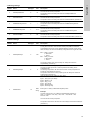
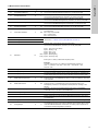
Faults in a CIM 150 PROFIBUS module can be detected by
observing the status of the two communication LEDs. See the
table below.
9.1.1 LED status
Fault (LED status)
Possible cause
Remedy
1. Both LEDs (LED1 and LED2) remain off
when the power supply is connected.
a) The CIM 150 is fitted incorrectly in the
DDA pump.
Check that the CIM 150 is fitted / connected
correctly.
b) The CIM 150 is defective.
Replace the CIM 150.
2. The LED for internal communication
(LED2) is flashing red.
a) No internal communication between the
CIM 150 and the DDA pump.
Check that the CIM 150 is fitted correctly in
the DDA pump.
3. The LED for internal communication
(LED2) is constantly red.
a) The CIM 150 does not support the
connected DDA pump.
Contact the nearest Grundfos company.
4. The PROFIBUS LED (LED1) is
constantly red.
a) Fault in the CIM 150.
5. The PROFIBUS LED (LED1) is flashing
red.
a) Fault in the CIM 150 PROFIBUS
configuration.
Contact the nearest Grundfos company.
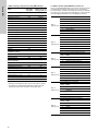
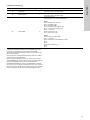
• Check that the PROFIBUS address
(switches SW3 and SW4) has a valid
value [1-126].
See section 5.4 Setting the PROFIBUS
address.
• Check that the GSD file used is correct.
• Check that the PROFIBUS cable has
been fitted correctly.
See section 5.3 Connecting the
PROFIBUS.
• Check that the PROFIBUS termination is
correct.
See section 5.5 Termination resistors.
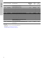
9.2 Fault finding CIM 500
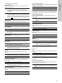
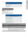
Faults in the CIM 500 can be detected by observing the status of
the two communication LEDs. See the table below and section
4.3 CIM 500 PROFINET IO.
9.2.1 LED status
Fault (LED status)
Possible cause
Remedy
1. Both LEDs (LED1 and LED2) remain off
when the power supply is connected.
a) The CIM 500 is fitted incorrectly in the
Grundfos product.
Check that the CIM 500 is fitted/connected
correctly.
b) The CIM 500 is defective.
Replace the CIM 500.
2. The PROFINET IO LED (LED1) remains
off.
a) The protocol selection switch (SW1)
has been set in Modbus TCP position
Set the switch to "0".
3. The LED for internal communication
(LED2) is flashing red.
a) No internal communication between the
CIM 500 and the Grundfos product.
Check that the CIM 500 is fitted correctly in
the Grundfos product.
4. The LED for internal communication
(LED2) is permanently red.
a) The CIM 500 does not support the
Grundfos product connected.
Contact the nearest Grundfos company.
5. The PROFINET IO LED (LED1) is
permanently red.
a) Connected Grundfos product is not
supported.
Contact the nearest Grundfos company.
b) Illegal position of protocol switch (SW1) Check that the rotary switch SW1 is set to
"0".
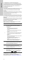
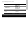
6. The PROFINET IO (LED1) is flashing
red.
a) Fault in the CIM 500 PROFINET IO
configuration.
• Check that the right GSDML file is used.
Check that PROFINET IO IP address
configuration is correct. See section A.4
PROFINET IO configuration on page 29.
• Check device name in the CIM 500 and
PROFINET IO master.
7. The PROFINET IO (LED1) is pulsing
red.
a) Connection to master lost.
• Check cables.
• Check master is running.
8. LED1 is permanently red and green at
the same time.
a) Error in firmware download.
Use the web server to download the
firmware again. See section A.2 Web
server configuration on page 28.
9. LED2 is permanently red and green at
the same time.
a) Memory fault.
Replace the CIM 500.
23