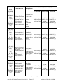
1
SIXNET IPm
IEC-60870-5
Slave Protocol Driver
User’s Manual
IPm IEC-60870 Slave Protocol Driver V2.0.0
Page 1
Preliminary, Rev r03, 11/5/2008
1. Table of contents
1.
Table of contents ................................................................................................................................2
2.
Index of Tables ...................................................................................................................................4
3.
Document Revision History ................................................................................................................6
4.
Introduction .........................................................................................................................................7
5.
SIXNET IPm IEC-60870-101/104 Implementation .............................................................................8
5.1
IPm IEC-60870-5 Slave Driver Implementation Table....................................................................9
5.2
SIXNET I/O to IEC-60870-5 Point Mappings ............................................................................... 12
5.2.1
General ................................................................................................................................. 12
5.2.2
Supported IEC-60870-5-101/104 Object Types ................................................................... 13
5.2.3
Supported IEC-60870-5-101/104 Monitoring Types............................................................. 18
5.2.3.1
Single-point information M_SP_NA_1........................................................................... 18
5.2.3.2
Double-point information M_DP_NA_1 ......................................................................... 20
5.2.3.3
Step-point Information M_ST_NA_1.............................................................................. 23
5.2.3.4
Normalized Measured Value M_ME_NA_1................................................................... 27
5.2.3.5
Scaled Measured Value M_ME_NB_1 .......................................................................... 31
5.2.3.6
Short floating point measured value M_NE_NC_1........................................................ 34
5.2.3.7
Integrated Totals-point Information M_IT_NA_1 ........................................................... 37
5.2.3.8
Normalized Measured Value without quality descriptor M_ME_ND_1.......................... 38
5.2.4
5.3
Supported IEC-60870-5-101/104 Command Types ............................................................. 39
5.2.4.1
Single-point Command C_SC_NA_1 ............................................................................ 39
5.2.4.2
Single-point Command with time tag C_SC_TA_1 (IEC-60870-5-104 only)................. 40
5.2.4.3
Double-point Command C_DP_NA_1 ........................................................................... 41
5.2.4.4
Double-point Command with time tag C_DC_TA_1 (IEC-60870-5-104 only) ............... 42
5.2.4.5
Regulating Step Command C_RC_NA_1 ..................................................................... 43
5.2.4.6
Regulating Step Command with time tag C_RC_TA_1 (IEC-60870-5-104 only).......... 44
5.2.4.7
Setpoint Command, Normalized Value C_SE_NA_1.................................................... 45
5.2.4.8
only) 46
Setpoint Co mmand with time tag, Normalized Val ue C_SE_TA_1 (IE C-60870-5-104
5.2.4.9
Setpoint Command, Scaled Value C_SE_NB_1. .......................................................... 47
5.2.4.10
only) 48
Setpoint Co mmand with time tag, Normalized Val ue C_SE_TB_1 (IE C-60870-5-104
5.2.4.11
Setpoint Command, Short Floating Point Value C_SE_NC_1 ...................................... 49
5.2.4.12
only) 50
Setpoint Co mmand with time tag, Norm alized Val ue C_SE_T C_1 (IEC-608 70-5-104
IPm IEC-60850-101/104 Driver Application Functions ................................................................ 52
5.3.1
Station Initialization ............................................................................................................... 52
5.3.2
Data acquisition by polling .................................................................................................... 52
IPm IEC-60870 Slave Protocol Driver V2.0.0
Page 2
Preliminary, Rev r03, 11/5/2008
5.3.3
Cyclic data transmission ....................................................................................................... 52
5.3.4
Acquisition of events ............................................................................................................. 52
5.3.5
General Interrogation ............................................................................................................ 53
5.3.6
Clock Synchronization .......................................................................................................... 54
5.3.7
Command Transmission (Controls) ...................................................................................... 54
5.3.8
Transmission of integrated totals (Counters)........................................................................ 55
5.3.9
Parameter Loading ............................................................................................................... 56
5.3.10
Test Procedure ..................................................................................................................... 56
5.3.11
File Transfer.......................................................................................................................... 56
5.3.12
Acquisition of time delay ....................................................................................................... 56
5.3.13
Background Scan.................................................................................................................. 56
5.3.14
Read Procedure.................................................................................................................... 57
5.4
IEC-60870-5 Communications..................................................................................................... 58
5.4.1
Communications Setup......................................................................................................... 58
5.4.2
Real Time Data Trace........................................................................................................... 58
6.
Run-Time Driver configuration..........................................................................................................59
6.1
Configuration tool requirements................................................................................................... 60
6.2
Configuration File format.............................................................................................................. 62
6.2.1
[General] Section parameter description .............................................................................. 63
6.2.2
[SxIPmStation] Section parameter description ..................................................................... 63
6.2.3
[DataLinkLayer] Section parameter description.................................................................... 63
6.2.4
[ApplicationLayer] Section parameter description ................................................................ 66
6.2.5
[M_SP_NA_1] Section parameter description ...................................................................... 67
6.2.6
[M_DP_NA_1] Section parameter description...................................................................... 69
6.2.7
[M_ST_NA_1] Section parameter description ...................................................................... 70
6.2.8
[M_ME_NA_1] Section parameter description ..................................................................... 72
6.2.9
[M_ME_NB_1] Section parameter description ..................................................................... 73
6.2.10
[M_ME_NC_1] Section parameter description ..................................................................... 74
6.2.11
[M_IT_NA_1] Section parameter description........................................................................ 75
6.2.12
[C_SC_NA_1] Section parameter description ...................................................................... 76
6.2.13
[C_DC_NA_1] Section parameter description ...................................................................... 78
6.2.14
[C_RC_NA_1] Section parameter description ...................................................................... 79
6.2.15
[C_SE_NA_1] Section parameter description ...................................................................... 81
6.2.16
[C_SE_NB_1] Section parameter description ...................................................................... 83
6.2.17
[C_SE_NC_1] Section parameter description ...................................................................... 85
6.3
Sample Configuration File............................................................................................................ 87
6.4
SIXNET IPm IEC-60870-5-101 Protocol interoperability Document............................................ 96
6.5
SIXNET IPm IEC-60870-5-104 Protocol interoperability Document............................................ 97
IPm IEC-60870 Slave Protocol Driver V2.0.0
Page 3
Preliminary, Rev r03, 11/5/2008
2. Index of Tables
Table 1 Supported IEC-60870-5 data types............................................................................................... 11
Table 2 Maximum number of information objects ...................................................................................... 13
Table 3: Information object addressing scheme......................................................................................... 17
Table 4 SIXNET X to IEC M_SP_NA_1 object mappings.......................................................................... 19
Table 5 SIXNET Y to IEC M_SP_NA_1 object mappings.......................................................................... 19
Table 6 SIXNET X pairs to IEC M_DP_NA_1 object mappings................................................................. 21
Table 7 SIXNET Y pairs to IEC M_DP_NA_1 object mappings................................................................ 21
Table 8 SIXNET AX to IEC M_ST_NA_1 object mappings, Analog step position mode ........................... 24
Table 9 SIXNET AX to IEC M_ST_NA_1 object mappings, Analog step position mode ........................... 24
Table 10 M_ST_NA_1 object mappings for monitoring C_RC_NA_1, Analog step position mode.......... 25
Table 11 M_ST_NA_1 object mappings for monitoring C_RC_NA_1, Digital step position mode ........... 25
Table 12 Parameter qualifiers .................................................................................................................... 27
Table 13 SIXNET AX to IEC M_ME_NA_1 object mappings, 1-octet IOA................................................. 29
Table 14 SIXNET AX to IEC M_ME_NA_1 object mappings, 2 and 3-octets IOA..................................... 29
Table 15 SIXNET AY to IEC M_ME_NA_1 object mappings..................................................................... 30
Table 16 SIXNET AX to IEC M_ME_NB_1 object mappings, 1-octet IOA................................................. 32
Table 17 SIXNET AX to IEC M_ME_NB_1 object mappings, 2 and 3-octets IOA..................................... 33
Table 18 SIXNET AY to IEC M_ME_NB_1 object mappings..................................................................... 33
Table 19 SIXNET FX to IEC M_ME_NC_1 object mappings, 1-octet IOA................................................. 36
Table 20 SIXNET FX to IEC M_ME_NC_1 object mappings, 2 and 3-octets IOA..................................... 36
Table 21 SIXNET FY to IEC M_ME_NC_1 object mappings..................................................................... 37
Table 22 SIXNET LX to IEC M_IT_NA_1 object mappings ....................................................................... 38
Table 23 SIXNET Y to IEC C_SC_NA_1 object mappings ........................................................................ 39
Table 24 Supported Command Qualifiers .................................................................................................. 40
Table 25 SIXNET Y pairs to IEC C_DC_NA_1 object mappings ............................................................... 41
Table 26 SIXNET Y to IEC C_RC_NA_1 object mappings........................................................................ 43
Table 27 SIXNET AY to IEC C_SE_NA_1 object mappings...................................................................... 46
Table 28 SIXNET AY to IEC C_SE_NB_1 object mappings...................................................................... 47
Table 29 SIXNET FY to IEC C_SE_NC_1 object mappings...................................................................... 50
Table 30 Event reporting type configuration............................................................................................... 53
Table 31 Station interrogation procedure ................................................................................................... 54
Table 32 Configuration File Sections ......................................................................................................... 62
Table 33 [General] section parameters ...................................................................................................... 63
Table 34 [SxIPmStation] section parameters ............................................................................................. 63
Table 35 [LinkLayer] section parameters ................................................................................................... 65
Table 36 [ApplicationLayer] section parameters ........................................................................................ 67
IPm IEC-60870 Slave Protocol Driver V2.0.0
Page 4
Preliminary, Rev r03, 11/5/2008
Table 37 [M_SP_NA_1] section parameters .............................................................................................. 68
Table 38 Group Reporting Mask Bits definition.......................................................................................... 69
Table 39 [M_DP_NA_1] section parameters.............................................................................................. 70
Table 40 [M_ST_NA_1] section parameters .............................................................................................. 72
Table 41 [M_ME_NA_1] section parameters ............................................................................................. 73
Table 42 [M_ME_NB_1] section parameters ............................................................................................. 74
Table 43 [M_ME_NC_1] section parameters ............................................................................................. 75
Table 44 [M_IT_NA_1] section parameters................................................................................................ 76
Table 45 [C_SC_NA_1] section parameters .............................................................................................. 78
Table 46 [C_SC_NA_1] section parameters .............................................................................................. 79
Table 47 [C_RC_NA_1] section parameters .............................................................................................. 81
Table 48 [C_SE_NA_1] section parameters .............................................................................................. 83
Table 49 [C_SE_NB_1] section parameters .............................................................................................. 84
Table 50 [C_SE_NC_1] section parameters .............................................................................................. 86
IPm IEC-60870 Slave Protocol Driver V2.0.0
Page 5
Preliminary, Rev r03, 11/5/2008
3. Document Revision History
Date
Rev
Who
Description of the Change
09/15/04
0
GMS
First preliminary draft. Circulated around SIXNET for
comments and approval.
12/11/06
1
SAS
Approved for implementation.
04/20/07
2
GMS
Updated after a second detailed review of IEC60850-5 specification documents and to include
object mapping design strategy and tables,
configuration tool requirements / specifications and
sample INI file sections
06/16/07
3
GMS
Updated after implementation of the first release of
the run-time driver (IPm part) to SIXNET. (driver
version 2.0.0).
IPm IEC-60870 Slave Protocol Driver V2.0.0
Page 6
Preliminary, Rev r03, 11/5/2008
4. Introduction
The pu rpose of this do cument is to d escribe th e pr eliminary spe cifications of the IEC-6 0870-5-101/104
Slave Protocol Driver for the SIXNET IPm family of open controllers and RTUs
The IEC-60 870-5-101/104 slave driver for SIXT RAK and VERS ATRAK IPm controlle rs i mplements a
SLAVE device function. It has been designed to enable data exchange with all types of I/O within the IPm
devices and to obtain th e maximum advantage of IP m features while providing full com pliance with IEC60870-5-101/104 standards.
The IEC-60870-5-101/1- 4 slave is highly configurable. It include s a Windows configuration utility, which
integrates into the SIXNE T I/O Tool Kit. The configur ation utility is callabl e from the “T ools Menu” of the
SIXNET I/O Tool Kit a nd enables the user to completely define and customize the run-time behavior of
the slave driver.
The SIXNET IPm Slave protocol driver implements the following IEC-60870-5 standard parts:
•
IEC 60870-5-101: Basic telecontrol tasks
•
IEC 60870-5-104: TCP/IP Network access for IEC 60870-5-101
The IEC 60870-5-101/1 04 proto col p rovides a standardized wa y to co mmunicate with oth er syste ms.
IEC 60870-5-101/104 provides a communication profile for sen ding basic telecontrol messages between
two systems, which u ses permanent, directly co nnected data ci rcuits between them. The IEC Techni cal
Committee 5 7 (Working Group 03 ) h ave develop ed a pr otocol standard fo r Telecontrol, Telep rotection,
and associated tele communications for ele ctric po wer systems. The re sult of this wo rk is IEC 60870-5.
Five documents specify the base IEC 60870-5. The documents are:
•
IEC 60870-5-1 Transmission Frame Formats
•
IEC 60870-5-2 Data Link Transmission Services
•
IEC 60870-5-3 General Structure of Application Data
•
IEC 60870-5-4 Definition and coding of Information Elements
•
IEC 60870-5-5 Basic Application Functions
The IEC Te chnical Com mittee 57 ha s also g enerated two companion standards IEC 60870-5-101 and
IEC 60870 -5-104 espe cially oriented for basi c teleco ntrol tasks a pplications. The IEC 6087 0-5-101/104
standards are based on the five documents IEC 60870-5-1 to 5. The IEC-60870-5-101/104 Slave protocol
for SIXNET-I Pm make IPm devices behave li ke a n IEC-6 0870-5-101 out station an d u ses V24/RS-232
communication lines, which can be connected directly to the Ma ster Unit or to a communication channel.
Also, networking support over Ethernet-TCP/IP as specified by IEC-60870-5-104 standard is supported.
The IEC-60870-5-101/104 slave proto col driver fo r SIXNET-IPm allows an IEC-6 0870-5-101/104 master
station to retrieve data a nd se nd commands to th e IPm device s. In unbala nced tra nsmission mo de the
master statio n is always the initia tor, i.e. the slave station can o nly send d ata if reque sted to do so.
SIXNET-IPm implementation of the IEC-608 70-5-101/104 slave p rotocol supports subsets of the ASDUs
in both control di rection and m onitoring di rection. T he follo wing sections of this document de scribe the
protocol implementation and the interoperability and conformity to the IEC specification.
IPm IEC-60870 Slave Protocol Driver V2.0.0
Page 7
Preliminary, Rev r03, 11/5/2008
5. SIXNET IPm IEC-60870-101/104 Implementation
The SIXNET IPm IEC-60870-5 slave driver package consist of three parts or modules:
•
The LINUX based Run-Time IEC-60870-5-101/104 driver module running within the IPm devices
•
The Microsoft Windows based Configuration Add-on program
•
The Microsoft Windows based on-line help documentation system
The Run-Time SIXNET IPm IEC-60870-5-101/104 slave driver module allows the SIXNET IPm devices to
respond to data read a nd write co mmands issued by a master unit connected to the IPm either on the
serial ports or on the TCP/IP network . The driver maps the SIXNET IPm Internal I/O Database to spe cific
IEC-60870-101 data objects thus making the IPm I/O database values available to IEC-60870-5-101/104
masters in both monitoring (READ) and Command (WRITE) modes. The slave driver m odule has been
developed in GNU-C.
The Run-Time SIXNET IPm IEC-60 870-5-101/104 sl ave d river i s configurable by th e mea ns of a
Microsoft Windows based configuration add-on tool, which is integrated to the SIXNET I/O Tool Kit via the
SIXNET’s sxaddon.dll lib rary. Using the configuration tool, the user has th e ability to configure the
following:
•
Mapping of Supported IEC-60870-5-101 data objects to SIXNET IPm database I/O registers
•
Communication mode: Se rial Port base d (IEC-60870-5-101) or T CP-UDP/IP based (IEC-608705-104)
•
Communications parameters (Baud rate, timeouts TCP port , etc)
The communications between the Configuration Add-On and the Run-Time module is done via an ASCII
text file generated and maintained by the Configuration Add-On, and downloadable to the IPm stations by
the means of the “User Files download” function of the SIXNET I/O Tool Kit.
The configuration Add-On program makes use of all current sxaddon.dll functions in order to automate as
long as po ssible the confi guration p rocess. In p articular, th e configuration a dd-on pe rform the follo wing
functions:
•
Read the list of IPm stations defined in the current project.
•
Maintain an ASCII config uration file fo r every station that has a n IEC-60 870-5-101/104 d river
installed and configured.
•
Maintain a master ASCII configuration file for the whole SIXNET I/O Tool Kit project.
•
Allow the user to sele ct a particular station from t he p roject st ation list and to define it s IEC60870-5-101/104 slave driver configuration.
•
Allow the user to d efine t he nu mber of IEC-60 870-5-101 data points for each of the supp orted
IEC-60870-5-101 data types and thei r mappin gs to SIXNET Registers (IEC-60870-5 datab ase
sizing and mapping)
•
Read the Ta g List of the selected station and allow the use r to define the SI XNET I/O to IEC 60870-5-101/104 object mappings and IEC-60870-5 monitoring group coding.
•
Define the behavior of the run-time slave driver.
•
Define the run-time
parameters.
•
Automatically upd ate the Communication Po rt Settings a ssignments i n the SIXNET Tool Kit
station’s configuration.
•
Update the “Files to Load” property of the statio n’s SIXNET I/O To ol Kit configu ration in order to
include the station’s IEC-60870-5 slave driver configuration INI file in the station’s files to load list.
slave driver
IPm IEC-60870 Slave Protocol Driver V2.0.0
communications mode
Page 8
(IEC-608070-5-101 or 1 04) and
Preliminary, Rev r03, 11/5/2008
5.1 IPm IEC-60870-5 Slave Driver Implementation Table
The following table i dentifies the IEC-60870-5-101/104 data types that are b e supported by the SIXNET
IPm IEC-60 870-5-101/104 slave p rotocol inte rface in both
monitor (read) an d com mand (write)
messages. T he definition and ma pping of SIXNET I/ O databa se variables into spe cific IEC-608 070-5101/104 data types is configurable.
Note: Values in (…) are references to IEC-60870-5-101 standard document
TYPE
ID
1
3
5
9
DATA
REPRESENTATION
CORRESPONDING
(MAPPABLE)
SIXNET I/O TYPE
AND ACCESS
DIRECTION
TYPE
DESCRIPTION
M_SP_NA_1
(7.3.1.1)
Monitored Single-point
Information.
This data type is used to store a
single binary input point.
Associated time-tagged event
information for this type are
M_SP_TA_1 (2) and
M_SP_TB_1 (30)
Single bit value
(7.2.6.1) with:
0=Off and 1=On.
DI
(READ)
M_DP_NA_1
(7.3.1.3)
Monitored Dual-point
Information.
This data type is used to store a
dual-point binary input value
(i.e., valve status). Associated
time-tagged event information
for this type are M_DP_TA_1 (4)
and M_DP_TB_1 (31).
Dual-bit status (7.2.6.2)
with:
00b (0 decimal) =
indeterminate or
intermediate,
01b (1 decimal) = Off,
10b (2 decimal) = On
and
11b (3 decimal) =
indeterminate.
DI
(READ)
M_ST_NA_1
(7.3.1.5)
Monitored Step-point
Information.
This data type is used for step
position of transformers or other
step position information. The
value for the position ranges
from -64 to 63. Associated timetagged event information for this
type are M_ST_TA_1 (6) and
M_ST_TB_1 (32).
Step data (7.2.6.5) is
stored in a single
character value with
bits 0-6 (-64 to +63)
representing the step
position and bit 7
representing the
following states:
0 = Equipment is not in
transient state
1 = Equipment in
transient state.
M_ME_NA_1
(7.3.1.9)
Monitored Normalized Measured
Value.
This data type is used for analog
input data. Associated timetagged event information for this
type are M_ME_TA_1 (10) and
M_ME_TD_1 (34).
Normalized values
(7.2.6.6) are stored in a
word (16-bit) data area
with a range of -1..+1-215
IPm IEC-60870 Slave Protocol Driver V2.0.0
Page 9
DI (Transient state)
+ AI (Step position)
Or
DI (Transient and
position states)
(READ)
AI
AO
(READ)
Preliminary, Rev r03, 11/5/2008
TYPE
ID
11
13
15
21
45
46
47
TYPE
DESCRIPTION
DATA
REPRESENTATION
CORRESPONDING
(MAPPABLE)
SIXNET I/O TYPE
AND ACCESS
DIRECTION
M_ME_NB_1
(7.3.1.11)
Monitored Scaled Measured
Value.
This data type is used for analog
input data. Associated timetagged event information for this
type are M_ME_TB_1 (12) and
M_ME_TE_1 (35).
Scaled values (7.2.6.7)
are stored in a word
(16-bit) data area with a
range of –215 .. +215-1
AI
AO
(READ)
M_ME_NC_1
(7.3.1.13)
Monitored Measured value,
short floating point number.
This data type is used for analog
input data. Associated timetagged event information for this
type are M_ME_TC_1 (14) and
M_ME_TF_1 (36).
Short floating point
number (7.2.6.9) are
stored in a double-word
(32-bit) data area in
IEEE STD 754 format
FI
FO
(READ)
M_IT_NA_1
(7.3.1.15)
Monitored Integrated Total-point
Information.
This data type is used to store
meter or other count data.
Associated time-tagged event
information for this type are
M_IT_TA_1 (16) and
M_IT_TB_1 (37).
Binary counter data
(7.2.6.9) is stored in a
double-word (32-bit)
value with a range of 31
31
2 ..+2 -1.
LI
(READ)
M_ME_ND_1
(7.3.1.21)
Normalized values
Monitored Normalized Measured
(7.2.6.6) are stored in a
Value without quality descriptor.
word (16-bit) data area
This data type is used for analog
with a range of -1..+1-2input data.
15
AI
AO
(READ)
C_SC_NA_1
(7.3.2.1)
Single bit value
Single-point Command
(7.2.6.15) With
This command is used to control
0 = Off
a single binary point such as a
and
relay.
1 = On
DO
(WRITE)
C_DC_NA_1
(7.3.2.2)
Double-point Command.
This command is used to control
a dual-point binary control
device such as a trip/close relay.
C_RC_NA_1
(7.3.2.3)
Regulating Step
Command (7.2.6.17)
Regulating Step Command
with
This command is used to control
0 = Not permitted
a stepping device such as a
1 = Next step lower
transformer.
2 = Next step higher
3 = Not permitted
IPm IEC-60870 Slave Protocol Driver V2.0.0
Page 10
Double Command
(7.2.6.16) with
0 = Not permitted
1 = Off
2 = On
3 = Not permitted
DO
(WRITE)
DO
(WRITE)
Preliminary, Rev r03, 11/5/2008
TYPE
ID
TYPE
DESCRIPTION
DATA
REPRESENTATION
CORRESPONDING
(MAPPABLE)
SIXNET I/O TYPE
AND ACCESS
DIRECTION
48
C_SE_NA_1
(7.3.2.4)
Normalized values
Setpoint Command, Normalized
(7.2.6.6) are stored in a
Value.
word (16-bit) data area
This command is used to control
with a range of
an analog device.
-1..+1-2-15
49
C_SE_NB_1
(7.3.2.5)
Setpoint Command, Scaled
Value.
This command is used to control
an analog device.
Scaled values (7.2.6.7)
are stored in a word
(16-bit) data area with a
range of -215 .. +215-1
AO
(WRITE)
C_SE_NC_1
(7.3.2.6)
Setpoint Command, Short Float
Value
This command is used to control
an analog device or
computation.
Short floats (7.2.6.8)
are stored in a doubleword (32-bit) data area
in IEEE STD 754
format.
FO
(WRITE)
50
AO
(WRITE)
Table 1 Supported IEC-60870-5 data types
IPm IEC-60870 Slave Protocol Driver V2.0.0
Page 11
Preliminary, Rev r03, 11/5/2008
5.2 SIXNET I/O to IEC-60870-5 Point Mappings
5.2.1 General
Every I/O register within the IPm I/O Database can be mapped into supported IEC-60870-5 data types as
described in Table 1
Due to the high amount of I/O registers available within the IPm database (and therefore the high amount
of IEC-60870-5 data points that can be made available to master devices), response messages to master
group read requests can b ecome very l arge in size. In order to limit the size of response messages, the
user is given the ability to limit, per IEC-60870-5 data type, the number of points availabl e in the IEC60870-5 virtual database. This featu re is co nfigurable in the SIXNET I/O Tool Kit using the SIXNET IPm
IEC-60870-5 Slave Driver configuration add-on.
IPm IEC-60870 Slave Protocol Driver V2.0.0
Page 12
Preliminary, Rev r03, 11/5/2008
5.2.2 Supported IEC-60870-5-101/104 Object Types
The SIXNET IPm IEC-60 870-5-101/104 Slave Driver supports the follo wing I EC-60870-5-101/104 d ata
types:
•
Single Points (1-bit discrete I/O), Monitor (READ) and Control (WRITE)
•
Double Points (2-bit, 4 state discrete I/O), Monitor (READ) and Control (WRITE)
•
Step positio n informatio n (128 -state enco ded variabl es I/O), Monitor (READ) and
(WRITE)
•
Measured Va lues (No rmalized o r Scale d or Fl oating Point analog I/O values) Monitor (REA D)
and Control (WRITE)
•
Integrated Values (32-bit counters) Monitor (READ)
Control
Any of these data types can be requested, in the monitor direction, with or without time tag information
Every SIXNET IPm I/O po int within the IPm Databa se can be m apped into o ne IEC-6 0870-5-101/104
point address as described in Table 1
Every SIXNET IPm st ation running the IEC-60870-5-101/104 slave protocol driver maintain a database
containing one block of a configur able number of contiguous IEC-60870-5-101/104 points for every IEC60870-5-101/104 d ata type su pported by the drive r (s ee Ta ble 1). Each on e of these blocks will be
mapped into a corresponding block of contiguous SIXNET registers of a compatible type (see Ta ble 1).
The SIXNET point addre ss of the first point in eac h map ped block is confi gurable. Any SIXNET I/O
variable that has a tag or a module assigned can be mapped into any IEC-60870-5 point as long as the
involved IEC-60870-5-101/104 point and the corresponding SIXNET I/O regi ster are type-compatible as
specified in Table 1
The IEC-60870-5-101/104 Information Object Address (IOA) range of the objects in eve ry mapped IEC
block is fixed and unique, as shown in Table 3
The SIXNET IPm IEC-60 870-5-101/015 drive r supports monito ring of sup ported IEC-60870-5-101/104
monitoring object types either without time tag, with regular time tag or with CP56 time tag.
The maximu m numbe r of distinct I/O obje cts in each type that can be configured and m apped into
SIXNET I/O points de pends on th e le ngth of th e I nformation O bject Ad dress -which can in tu rn be
configured to be 1, 2 or 3 o ctets l ong- the si ze of the SIXNET I/O datab ase for the corresponding
SIXNET I/O type and th e fact that the I EC-60870-5-101/104 information obj ect address m ust be u nique
across all supported IEC-68070-5-101/104 object types.
The following tables show the maximum number of in formation objects that can be defined for ea ch of
the supp orted IEC type s and th e info rmation o bjects a ddress range th at ca n be m apped into SIXNET
registers as a function of the Information Object Address length:
Length of the Information Address
Field (octets)
Maximum number of unique IEC60870-5-101 information elements
per type
18
2 1024*
3 1024*
Table 2 Maximum number of information objects
* Can’t exceed the size of the IPm I/O database.
IPm IEC-60870 Slave Protocol Driver V2.0.0
Page 13
Preliminary, Rev r03, 11/5/2008
TYPE
(IEC-608705-101
Paragraph)
(Type ID)
DESCRIPTION
DATA
REPRESENTATION
INFORMATION OBJECT ADDRESS RANGE
(IN HEXADECIMAL FORMAT)
1-Octet IOA
2-Octet IOA
3-Octet IOA
Monitored Singlepoint Information.
This data type is used
to store a single
M_SP_NA_1 binary input point.
Single bit value
(7.3.1.1)
Associated time(7.2.6.1) with:
(1)
tagged event
0=Off and 1=On.
information for this
type are M_SP_TA_1
(2) and M_SP_TB_1
(30)
0x00-0x07
0x00000x03FF
0x0000000x0003FF
Monitored Dual-point
Information.
This data type is used
to store a dual-point
binary input value
M_DP_NA_1
(i.e., valve status).
(7.3.1.3)
Associated time(3)
tagged event
information for this
type are M_DP_TA_1
(4) and M_DP_TB_1
(31).
Dual-bit status
(7.2.6.2) with:
00b (0 decimal)
= indeterminate
or intermediate,
01b (1 decimal)
= Off,
10b (2 decimal)
= On
and
11b (3 decimal)
= indeterminate.
0x08-0x0F
0x04000x07FF
0x0004000x0007FF
Monitored Step-point
Information.
This data type is used
for step position of
transformers or other
step position
M_ST_NA_1 information. The
value for the position
(7.3.1.5)
(5)
ranges from -64 to
63. Associated timetagged event
information for this
type are M_ST_TA_1
(6) and M_ST_TB_1
(32).
Step data
(7.2.6.5) is
stored in a single
character value
with bits 0-6 (-64
to +63)
representing the
step position and
bit 7
representing the
following states:
0 = Equipment is
not in transient
state
1 = Equipment in
transient state.
0x10-0x17
0x08000x0BFF
0x0008000x000BFF
IPm IEC-60870 Slave Protocol Driver V2.0.0
Page 14
Preliminary, Rev r03, 11/5/2008
TYPE
(IEC-608705-101
Paragraph)
(Type ID)
DESCRIPTION
Monitored
Normalized
Measured Value.
This data type is used
M_ME_NA_1 for analog input data.
(7.3.1.9)
Associated time(9)
tagged event
information for this
type are M_ME_TA_1
(10) and
M_ME_TD_1 (34).
Monitored Scaled
Measured Value.
This data type is used
for analog input data.
M_ME_NB_1
Associated time(7.3.1.11)
tagged event
(11)
information for this
type are M_ME_TB_1
(12) and
M_ME_TE_1 (35).
Monitored Measured
value, short floating
point number.
This data type is used
for analog input data.
M_ME_NC_1
Associated time(7.3.1.13)
tagged event
(13)
information for this
type are
M_ME_TC_1 (14)
and M_ME_TF_1
(36).
DATA
REPRESENTATION
INFORMATION OBJECT ADDRESS RANGE
(IN HEXADECIMAL FORMAT)
1-Octet IOA
Normalized
values (7.2.6.6)
are stored in a
word (16-bit)
data area with a
range of -1..+12-15
2-Octet IOA
3-Octet IOA
0x0C000x0FFF
0x000C000x000FFF
0x10000x03FF (P1)
0x0010000x0003FF (P1)
0x14000x28-0x2F(M1) 0x17FF (M1)
0x0014000x0017FF (M1)
0x30-0x37(M2)
0x18000x1BFF (M2)
0x0018000x001BFF (M2)
0x1C00
0x1FFF (M3)
0x001C00
0x001FFF (M3)
0x20000x23FF
0x0020000x0023FF
0x24000x27FF (P1)
0x0024000x0027FF (P1)
0x28000x2BFF(M1)
0x0028000x002BFF(M1)
0x2C000x2FFF(M2)
0x002C000x002FFF(M2)
0x30000x33FF(M3)
0x0030000x0033FF(M3)
0x34000x37FF
0x0034000x0037FF
0x38000x3BFF(P1)
0x0038000x003BFF(P1)
0x3C000x3FFF(M1)
0x003C000x003FFF(M1)
0x40000x43FF(M1)
0x0040000x0043FF(M1)
0x44000x47FF(M3)
0x0044000x0047FF(M3)
0x18-0x1F
0x20-0x27(P1)
0x38-0x3F(M3)
0x40-0x47
Scaled values
0x48-0x4F(P1)
(7.2.6.7) are
stored in a word
0x50-0x57(M1)
(16-bit) data area
with a range of –
0x58-0x5F(M2)
15
15
2 .. +2 -1
0x60-0x67(M3)
0x68-0x6F
Short floating
point number
0x70-0x77(P1)
(7.2.6.9) are
stored in a
0x78-0x7F(M1)
double-word (32bit) data area in
0x80-0x87(M2)
IEEE STD 754
format
0x88-0x8F(M3)
IPm IEC-60870 Slave Protocol Driver V2.0.0
Page 15
Preliminary, Rev r03, 11/5/2008
TYPE
(IEC-608705-101
Paragraph)
(Type ID)
DESCRIPTION
M_IT_NA_1
(7.3.1.15)
(15)
Monitored Integrated
Total-point
Information.
This data type is used
to store meter or
other count data.
Associated timetagged event
information for this
type are M_IT_TA_1
(16) and M_IT_TB_1
(37).
Monitored
Normalized
M_ME_ND_1 Measured Value
(7.3.1.21)
without quality
(21)
descriptor.
This data type is used
for analog input data.
C_SC_NA_1
(IEC 608705-101:
7.3.2.1)
(45)
Single-point
Command (-101) and
Single point
command with time
tag (-104):
This command is
C_SC_TA_1 used to control a
(IEC 60870- single binary point
5-104: 8.1) such as a relay.
(58)
C_DC_NA_1
(IEC 608705-101:
7.3.2.2)
(46)
Double-point
Command (-101)
and. Double-point
Command with time
tag (-104):
This command is
C_DC_TA_1 used to control a
(IEC 60870- dual-point binary
5-104: 8.2) control device such
(59)
as a trip/close relay.
DATA
REPRESENTATION
INFORMATION OBJECT ADDRESS RANGE
(IN HEXADECIMAL FORMAT)
1-Octet IOA
2-Octet IOA
3-Octet IOA
Binary counter
data (7.2.6.9) is
stored in a
double-word (32bit) value with a
range of 31
31
2 ..+2 -1.
0x90-0x97
0x48000x4BFF
0x0048000x004BFF
Normalized
values (7.2.6.6)
are stored in a
word (16-bit)
data area with a
range of -1..+12-15
0x18-0x1F
0x0C000x0FFF
0x000C000x000FFF
0x4C000x4FFF (C)
0x004C000x004FFF (C)
0x50000x53FF (M)
0x0050000x0053FF (M)
0x54000x57FF (C)
0x0054000x0057FF (C)
0x58000x5BFF (M)
0x0058000x005BFF (M)
Single bit value
(7.2.6.15) With
0 = Off
and
1 = On
Double
Command
(7.2.6.16) with
0 = Not
permitted
1 = Off
2 = On
3 = Not
permitted
IPm IEC-60870 Slave Protocol Driver V2.0.0
Page 16
0x98-0x9F (C)
0xA0-0xA7 (M)
0xA8-0xAF(C)
0xB0-0xB7(M)
Preliminary, Rev r03, 11/5/2008
TYPE
(IEC-608705-101
Paragraph)
(Type ID)
DESCRIPTION
C_RC_NA_1
(IEC 608705-101:
7.3.2.3)
(47)
Regulating Step
Command (-101) and
Regulating Step
command with time
tag (-104):
This command is
C_RC_TA_1
used to control a
(IEC 60870stepping device such
5-104: 8.3)
as a transformer.
(60)
C_SE_NA_1
(IEC 608705-101:
7.3.2.4)
(48)
Setpoint Command,
Normalized Value (101) and Setpoint
Command with time
tag, Normalized
C_SE_TA_1 Value (-104):
(IEC 60870- This command is
5-104: 8.4) used to control an
(61)
analog device.
C_SE_NB_1
(IEC 608705-101:
7.3.2.5)
(49)
Setpoint Command,
Scaled Value (-101)
and Setpoint
Command with time
tag, Scaled Value
(-104) :
C_SE_TB_1
This command is
(IEC 60870used to control an
5-104: 8.5)
analog device.
(62)
C_SE_NC_1
(IEC 608705-101:
7.3.2.6)
(50)
Setpoint Command,
Short Float Value
(-101) and
Setpoint Command
with time tag, Short
Float Value (-104):
C_SE_TB_1 This command is
(IEC 60870- used to control an
5-104: 8.6) analog device or
(63)
computation.
DATA
REPRESENTATION
Regulating Step
Command
(7.2.6.17) with
0 = Not
permitted
1 = Next step
lower
2 = Next step
higher
3 = Not
permitted
Normalized
values (7.2.6.6)
are stored in a
word (16-bit)
data area with a
range of
-15
-1..+1-2
INFORMATION OBJECT ADDRESS RANGE
(IN HEXADECIMAL FORMAT)
1-Octet IOA
2-Octet IOA
3-Octet IOA
0xB8-0xBF(C)
0x5C000x5FFF (C)
0x005C000x005FFF (C)
0x60000x63FF (M)
0x0060000x0063FF (M)
0x64000x67FF (C)
0x0064000x0067FF (C)
0x68000x6BFF (M)
0x0068000x006BFF (M)
0x6C000x6FFF (C)
0x006C000x006FFF (C)
0x70000x73FF (M)
0x0070000x0073FF (M)
0x74000x77FF (C)
0x0074000x0077FF (C)
0x78000x7BFF (M)
0x0078000x007BFF (M)
0xC0-0xC7(M)
0xC8-0xCF(C)
0xD0-0xD7(M)
Scaled values
(7.2.6.7) are
0xD8-0xDF(C)
stored in a word
(16-bit) data area
0xE0-0xE7(M)
with a range of 15
15
2 .. +2 -1
Short floats
(7.2.6.8) are
stored in a
double-word (32bit) data area in
IEEE STD 754
format.
0xE8-0xEF(C)
0xF0-0xF7(M)
Table 3: Information object addressing scheme
IPm IEC-60870 Slave Protocol Driver V2.0.0
Page 17
Preliminary, Rev r03, 11/5/2008
Notes:
(C): Object address in control direction (Write)
(M): Object in monitor direction (Read)
(P1): Parameter 1 (Deadband) in control direction (Write)
(M1): Parameter 1 (Deadband) in monitor direction (Read)
(M2): Parameter 2 (High limit for event transmission of metered values) in monitor direction (Read)
(M3): Parameter 3 (Low limit for event transmission of metered values) in monitor direction (Read)
5.2.3 Supported IEC-60870-5-101/104 Monitoring Types
5.2.3.1
Single-point information M_SP_NA_1
One block of up to 1024 (8 for 1-byte informatio n object address, see Table 2) of contiguous IEC-608705-101/104 M _SP_NA_1 single poi nt Information variable s ca n b e defined a nd mappe d to SIXNET X
registers within any given IPm station.
The starting address of the mapped SIXNET X blo ck, i.e. the a ddress of the f irst mapped X register, as
well as the number of M_SP_NA_1 objects, i.e. the number of mapped X registers, are configurable
The first conf igured M_SP _NA_1 sin gle point info rmation obj ect within the block has the fo llowing IEC
information object address (IOA):
•
0x00 if length of Information Object Address is 1 octet
•
0x0000 if length of Information Object Address is 2 octets
•
0x000000 if length of Information Object Address is 3 octets
Also If any C_SC_ NA_1 single control informatio n objects block have been mapped to Y registe rs (see
5.2.4), o ne block of up to 102 4 (8 fo r 1-byte i nformation object address, s ee Tabl e 2 ) of contiguous
M_SP_NA_1 single p oint information variables will be mapped to the sam e Y regi sters, in orde r to
provide for monitoring capabilities to C_SC_NA_1 discrete output (control) objects.
The first configured M_S P_NA_1 di screte o utput monitoring single point inf ormation o bject, ha s th e
following IEC information object address (IOA):
•
0xA0 if length of Information Object Address is 1 octet
•
0x5000 if length of Information Object Address is 2 octets
•
0x005000 if length of Information Object Address is 3 octets
The nu mbers of SIXNET X and Y
independently configurable.
registers ma pped to single-point info rmation IEC obje cts a re
If the user sets the num ber of M_SP_NA_1 obje cts mapped to SIXNET X regi sters to 0, no SIXNET X
registers will be reported as M_SP_NA_1 objects by the IPm.
If the user sets the num ber of C_SC_NA_1 si ngle control i nformation o bjects m apped to SIXNET Y
registers to 0, no SIXNET Y registers will be reported as M_SP_NA_1 objects by the IPm.
IPm IEC-60870 Slave Protocol Driver V2.0.0
Page 18
Preliminary, Rev r03, 11/5/2008
If the user sets both, the numbe r of M_SP_NA_ 1 object s map ped to SIXNET X and the numbe r of
C_SC_NA_1 obje cts ma pped to SIX NET Y re gisters to 0, n o M_SP_NA_ 1 Single -point information
objects at all will exist within the IPm.
The following tables show the actual mapping-addressing scheme for M_SP_NA_1 objects as a function
of the configured IEC information object address length:
SIXNET X Registers to IEC M_SP_NA_1 Object Mapping
1-octet object address
(Up to 8 registers*)
2-octet object address
(Up to 1024 registers*)
3-octet object address
(Up to 1024 registers*)
SIXNET
Register
M_SP_NA_1
IOA
SIXNET
Register
M_SP_NA_1
IOA
SIXNET
Register
M_SP_NA_1
IOA
X[n]
0x00
(0)
X[n]
0x0000
(0)
X[n]
0x000000
(0)
X[n+1]
0x01
(1)
X[n+1]
0x0001
(1)
X[n]
0x000001
(1)
…
…
…
…
…
…
X[n+7]*
0x07*
(7)
X[n+1023]*
0x03FF*
(1023)
X[n+1023]*
0x0003FF*
(1023)
Table 4 SIXNET X to IEC M_SP_NA_1 object mappings
* Configurable. The actual number of SIXNET X registers that can be mapped to M_SP_NA_1
objects can be lower, depending on how many X registers have been mapped to other compatible
IEC types (see Table 1) and I/O database capacity
** n: Configured starting SIXNET X address of the M_SP_NA_1 mapped block
SIXNET Y Registers to IEC M_SP_NA_1 Object Mapping
1-octet object address
(Up to 8 registers*)
2-octet object address
(Up to 1024 registers*)
3-octet object address
(Up to 1024 registers*)
SIXNET
Register
M_SP_NA_1
IOA
SIXNET
Register
M_SP_NA_1
IOA
SIXNET
Register
M_SP_NA_1
IOA
Y[m]
0xA0
(160)
Y[m]
0x5000
(20480)
Y[m]
0x005000
(20480)
Y[m+1]
0xA1
(161)
Y[m+1]
0x5001
(20481)
Y[m+1]
0x005001
(20481)
…
…
…
…
…
…
Y[m+7]*
0xA7*
(167)
Y[m+1023]*
0x53FF*
(21503)
Y[m+1023]*
0x0053FF*
(21503)
Table 5 SIXNET Y to IEC M_SP_NA_1 object mappings
* Configurable. The actual number of SIXNET Y registers that can be mapped to M_SP_NA_1
objects can be lower; depending on how many Y registers have been mapped to other compatible
IEC types (see Table 1) and I/O database capacity
** m: Configured starting SIXNET Y address of the C_SC_NA_1 mapped block
SIXNET X and Y regi sters m apped a s IEC-6080 70-5-101/104 Single Point Information With
Descriptor points are reported as follows:
•
Single Point Information (SPI) Bit
•
Reserve (RES)
(Bit
IPm IEC-60870 Slave Protocol Driver V2.0.0
Quality
(Bit 0) = 0 or 1, current state of SIXNET X register
=
1)
0, Reserved
Page 19
Preliminary, Rev r03, 11/5/2008
•
Reserve (RES)
(Bit
=
2)
0, Reserved
•
Reserve (RES)
(Bit
=
3)
0, Reserved
•
Blocked (BL)
(Bit
=
4)
0, Not Blocked
•
Substituted (SB)
(Bit 5) = 0, Not Substituted
•
Not Topical (NT)
(Bit 6) = 0, Topical
•
Invalid (IV)
(Bit
=
7)
0, Valid
This means that the value reported for the mapped SIXNET register is 0x01 if the co rresponding binary
register is ON or 0x00 if the corresponding register is OFF.
5.2.3.2
Double-point information M_DP_NA_1
One block of up to 1024 (8 for 1-byte informatio n object address, see Table 2) of contiguous IEC-608705-101/104 M _DP_NA_1 d ouble p oint Informatio n o bjects ca n b e defined a nd mappe d to SIXNET X
registers within any given IPm station.
One X register p air (two contiguous X regi sters) wi ll be ma pped per each M _DP_NA_1 double-point
information object
The sta rting address of the mappe d SIXN ET X block, i.e. the addre ss of t he first X registe r of the first
mapped X register p air, a s well a s the number of M_DP_NA_1 objects, i.e. the numbe r of mapped X
register pairs, are configurable
The first configured M_DP_NA_1 Double Point Information object within the block, which is mapped to the
first X register pair, has the following IEC information object address (IOA):
•
0x08 if length of Information Object Address is 1 octet
•
0x0400 if length of Information Object Address is 2 octets
•
0x000400 if length of Information Object Address is 3 octets
Also If any C_DC_NA_1 double control objects block has been mapped to Y registers pairs (see 5.2.3.2),
one block of up to 1024 (8 for 1-byte information object address, see Table 2) of contiguous M_DP_NA_1
Single Point Information variabl es will be ma pped t o same Y registe r p airs, in o rder to provide for
monitoring capabilities to C_DC_NA_1 discrete output (control) objects.
The first configured M_DP_NA_1 control-monitoring double point Information object has the following IEC
information object address (IOA):
•
0xB0 if length of Information Object Address is 1 octet
•
0x5800 if length of Information Object Address is 2 octets
•
0x005800 if length of Information Object Address is 3 octets
The numb ers of SIXNET X and Y r
independently configurable.
egisters p airs mapped to double -point information objects are
If the user sets the number of M_DP_NA_1 objects mapped to SIXNET X register pairs to 0, no SIXNET
X register pairs will be reported as M_DP_NA_1 objects by the IPm.
If the user sets the number of C_DC_NA_1 double control objects mapped to SIXNET Y register pairs to
0, no SIXNET Y register pairs will be reported as M_DP_NA_1 objects by the IPm.
IPm IEC-60870 Slave Protocol Driver V2.0.0
Page 20
Preliminary, Rev r03, 11/5/2008
If the user se ts both, the numbe r of M_DP_NA_1 objects mapped to SIXNET X pairs and the number of
C_DC_NA_1 objects mapped to SIXNET Y regi ster pairs to 0, no M_DP_NA_1 Double-point information
objects at all will exist within the IPm.
The following tables show the actual mapping-addressing scheme for M_DP_NA_1 objects as a function
of the configured IEC information object address length:
SIXNET X Registers to IEC M_DP_NA_1 Object Mapping
1-octet object address
(Up to 8 registers*)
2-octet object address
(Up to 1024 registers*)
3-octet object address
(Up to 1024 registers*)
SIXNET
Registers**
M_DP_NA_1
IOA
SIXNET
Registers**
M_DP_NA_1
IOA
SIXNET
Registers**
M_DP_NA_1
IOA
X[m],
X[m+1]
0x08
(8)
X[m],
X[m+1]
0x0400
(1024)
X[m],
X[m+1]
0x000400
(1024)
X[m+2],
X[m+3]
0x09
(9)
X[m+2],
X[m+3]
0x0401
(1025)
X[m+2],
X[m+3]
0x000401
(1025)
…
…
…
…
…
…
X[m+14],
X[m+15]*
0x0F
(15)*
X[m+2046],
X[m+2047]*
0x07FF*
(2047)
X[m+2046],
X[m+2047]*
0x0007FF*
(2047)
Table 6 SIXNET X pairs to IEC M_DP_NA_1 object mappings
* Configurable. The actual number of SIXNET X register pairs that can be mapped to M_DP_NA_1
objects can be lower, depending on how many X registers have been mapped to other compatible
IEC types (see Table 1) and I/O database capacity
** m: Configured starting SIXNET X address of the M_DP_NA_1 mapped block
SIXNET Y Registers to IEC M_DP_NA_1 Object Mapping
1-octet object address
(Up to 8 registers*)
2-octet object address
(Up to 1024 registers*)
3-octet object address
(Up to 1024 registers*)
SIXNET
Registers**
M_DP_NA_1
IOA
SIXNET
Registers**
M_DP_NA_1
IOA
SIXNET
Registers**
M_DP_NA_1
IOA
Y[n],
Y[n+1]
0xB0
(176)
Y[n],
Y[m+1]
0x5800
(22528)
Y[n],
Y[n+1]
0x5800
(22528)
Y[n+2],
Y[n+3]
0xB1
(177)
Y[n+2],
Y[n+3]
0x5801
(22529)
Y[n+2],
Y[n+3]
0x5801
(22529)
…
…
…
…
…
…
Y[n+14],
Y[n+15]*
0xB7
(183)*
Y[n+2046],
Y[n+2047]*
0x5BFF*
(23551)
Y[n+2046],
Y[n+2047]*
0x5BFF*
(23551)
Table 7 SIXNET Y pairs to IEC M_DP_NA_1 object mappings
* Configurable. The actual number of SIXNET Y registers that can be mapped to M_DP_NA_1
objects can be lower; depending on how many Y registers have been mapped to other compatible
IEC types (see Table 1) and I/O database capacity
** n: Configured starting SIXNET Y address of the C_DC_NA_1 mapped block
IPm IEC-60870 Slave Protocol Driver V2.0.0
Page 21
Preliminary, Rev r03, 11/5/2008
SIXNET X and Y re gister pairs ma pped a s IEC-6 08070-5-101 Dou ble Poin t Information With Q uality
Descriptor points are reported as follows:
•
Double Point Information (DPI) Bits
(Bit 0, Bit1) = SIXNET DI Register 1 and Register 2
00 = Indeterminate
01 = OFF
10 = ON
11 = Indeterminate
•
Reserve (RES)
(Bit
=
2)
0, Reserved
•
Reserve (RES)
(Bit
=
3)
0, Reserved
•
Blocked (BL)
(Bit
=
4)
0, Not Blocked
•
Substituted (SB)
(Bit 5) = 0, Not Substituted
•
Not Topical (NT)
(Bit 6) = 0, Topical
•
Invalid (IV)
(Bit
=
7)
0, Valid
This means that the val ues reported will be 0x0 0, 0x01, 0x02 or 0x03 depending on the corresponding
value of the mapped X or Y register pair.
IPm IEC-60870 Slave Protocol Driver V2.0.0
Page 22
Preliminary, Rev r03, 11/5/2008
5.2.3.3
Step-point Information M_ST_NA_1
The SIXNET IPm IEC-60870-5 slave driver can be configured to read the all the Step Position Information
objects in one of the two following modes:
•
Analog Step Position Mode: In this mode, the step position part of the M_ST_NA_1 object is read
from an AX register and the transient bit of the M_ST_NA_1 is read from an X register, so, in this
mode of ope ration, one AX registe r an d one X r egister must be mappe d for e ach M_ST_NA_1
information object
•
Digital Step Position M ode: In this mo de, both, the step p osition and th e tra nsient bit are rea d
from a co ntiguous blo ck o f eight (8) X regi sters, so, eight contig uous (8 ) X registe rs m ust be
mapped for each M_ST_NA_1 information object. The first seven (7) X register are interpreted as
the step position information in 2’s complement binary representation (-64 to +63 values) and the
eighth (8th) bit is the Transient State bit.
One block of up to 1 024 (8 for 1 -byte information object address, see Ta ble 2) contiguous IEC-60870-5101/104 M_ST_NA_1 Monitored Step Point Information variables can be defined and mapped to SIXNET
AX and X register p airs when the drive r is co nfigured in the anal og step p osition mode o r to blocks of
eight (8) X registers when the driver is configured in the binary-encoded digital step position mode.
When the driver is config ured in the analog ste p position mo de, the sta rting add ress of the ma pped
SIXNET AX block (for p osition info rmation input ) an d the starting address of the SIXNET X block (f or
transient state input), i.e. t he ad dress o f the first ma pped AX, X registe r pair, as well a s th e number of
M_ST_NA_1 objects, i.e. t he number of mapped AX, X re gister pairs, are configurable. One (1) AX a nd
one (1) X register must be allocated per M_ST_NA_1 object
When the driver is configured in the digital ste p p osition mode, the sta rting add ress of the map ped
SIXNET X block (for po sition and transient state information input), i.e. the address of the first mappe d X
register, a s well a s the number of M _ST_NA_1 o bjects, i.e. the numb er of mappe d X registe rs are
configurable. Eight (8) X registers must be allocated per M_ST_NA_1 object
The first conf igured M_ST _NA_1 Step Point Informa tion obje ct wi thin the blo ck, ha s the fol lowing IEC
information object address (IOA):
•
0x10 if length of Information Object Address is 1 octet
•
0x0800 if length of Information Object Address is 2 octets
•
0x000800 if length of Information Object Address is 3 octets
Also If any C_RC_ NA_1 regulating step command information objects register block have been mapped
to Y regi ster pairs (see 00), the u ser must also create one block of up to 1024 (8 fo r 1-byte information
object address, see Table 2) of contiguous M_ST_NA_1 step point information objects, in a M_ST_NA_1
object per C_RC_NA_1 object basi s, in order to provide for m onitoring ca pabilities to C_RC_NA_1
regulating step command objects and then m ap the so created M_ST_NA_1 either to their own sets of
contiguous AX, X register pairs (if the d river has been configured in the Analog step position information
mode) or to their own sets of contiguous groups of eight (8) X registers (if the driver has been configured
in the digital step position information mode)
The first conf igured M_ST _NA_1 step point inform ation obje ct provided for m onitoring of C_ RC_NA_1
regulating step command information objects has the following IEC information object address (IOA):
•
0xC0 if length of Information Object Address is 1 octet
•
0x6000 if length of Information Object Address is 2 octets
•
0x006000 if length of Information Object Address is 3 octets
IPm IEC-60870 Slave Protocol Driver V2.0.0
Page 23
Preliminary, Rev r03, 11/5/2008
The numbers of SIXNET AX an
independently configurable.
d AY regi sters map ped to M_ST_ NA_1 info rmation obj ects a re
If the user sets the number of M_ST_NA_1 objects to 0, no SIXNET AX or X registers will be reported as
M_ST_NA_1 objects by the IPm.
If the use r sets th e nu mber of C_ RC_NA_1 si ngle control information o bjects map ped to 0, no
M_ST_NA_1 monitoring objects for C_RC_NA_1 monitoring will be created or reported by the IPm.
If the user sets both, the number of M_ST_NA_1 objects and the number of C_RC_NA_1 objects to 0, no
M_ST_NA_1 information objects at all will exist within the IPm.
The following tables show the actual mapping-addressing scheme for M_ST_NA_1 objects as a function
of the configured IEC information object address length:
SIXNET AX and X Registers to IEC M_ST_NA_1 Object Mapping
Analog Step Position Mode
1-octet object address
(Up to 8 registers*)
2-octet object address
(Up to 1024 registers*)
3-octet object address
(Up to 1024 registers*)
SIXNET
Register**
M_ST_NA_1
IOA
SIXNET
Register**
M_ST_NA_1
IOA
SIXNET
Register**
M_ST_NA_1
IOA
AX[n],
X[m]
0x10
(16)
AX[n],
X[m]
0x0800
(2048)
AX[n],
X[m]
0x000800
(2048)
AX[n+1],
X[m+1]
0x11
(17)
AX[n+1],
X[m+1]
0x0801
(2049)
AX[n+1],
X[m+1]
0x000801
(2049)
…
…
…
…
…
…
AX[n+7],
X[m+7]*
0x17*
(23)
AX[n+1023],
X[m+1023]*
0x0BFF*
(3071)
AX[n+1023],
X[m+1023]*
0x000BFF*
(3071)
Table 8 SIXNET AX to IEC M_ST_NA_1 object mappings, Analog step position mode
SIXNET AX and X Registers to IEC M_ST_NA_1 Object Mapping
Digital Step Position Mode
1-octet object address
(Up to 8 registers*)
2-octet object address
(Up to 1024 registers*)
3-octet object address
(Up to 1024 registers*)
SIXNET
Register**
M_ST_NA_1
IOA
SIXNET
Register**
M_ST_NA_1
IOA
SIXNET
Register**
M_ST_NA_1
IOA
X[m]X[m+7]
0x10
(16)
X[m]X[m+7]
0x0800
(2048)
X[m]X[m+7]
0x000800
(2048)
X[m+8]X[m+15]
0x11
(17)
X[m+8]X[m+15]
0x0801
(2049)
X[m+8]X[m+15]
0x000801
(2049)
…
…
…
…
…
…
X[m+56]X[m+63]*
0x17*
(23)
X[m+8184]X[m+8191]*
0x0BFF*
(3071)
X[m+8184]X[m+8191]*
0x000BFF*
(3071)
Table 9 SIXNET AX to IEC M_ST_NA_1 object mappings, Analog step position mode
* Configurable. The actual number of SIXNET AX, X registers that can be mapped to M_ST_NA_1
objects can be lower, depending on how many AX registers have been mapped to other
compatible IEC types (see Table 1) and I/O database capacity
** n, m: Configured starting SIXNET AX and X address of the M_ST_NA_1 mapped block
IPm IEC-60870 Slave Protocol Driver V2.0.0
Page 24
Preliminary, Rev r03, 11/5/2008
SIXNET AY, X Registers to IEC M_ST_NA_1 Object Mapping (for C_RC_NA_1 monitoring)
Analog Step Position Mode
1-octet object address
(Up to 8 registers*)
2-octet object address
(Up to 1024 registers*)
3-octet object address
(Up to 1024 registers*)
SIXNET
Register**
M_ST_NA_1
IOA
SIXNET
Register**
M_ST_NA_1
IOA
SIXNET
Register**
M_ST_NA_1
IOA
AX[j],
X[k]
0xC0
(192)
AX[j],
X[k]
0x6000
(24576)
AX[j],
X[k]
0x006000
(24576)
AX[j+1],
X[k+1]
0xC1
(193)
AX[j+1],
X[k+1]
0x6001
(24577)
AX[j+1],
X[k+1]
0x006001
(24577)
…
…
…
…
…
…
AX[j+7],
X[k+7]*
0xC7*
(199)
AX[j+1023],
X[k+1023]*
0x63FF*
(25599)
AX[j+1023],
X[k+1023]*
0x0063FF*
(25599)
Table 10 M_ST_NA_1 object mappings for monitoring C_RC_NA_1, Analog step position mode
SIXNET AX, X Registers to IEC M_ST_NA_1 Object Mapping (for C_RC_NA_1 monitoring)
Digital Step Position Mode
1-octet object address
(Up to 8 registers*)
2-octet object address
(Up to 1024 registers*)
3-octet object address
(Up to 1024 registers*)
SIXNET
Register**
M_ST_NA_1
IOA
SIXNET
Register**
M_ST_NA_1
IOA
SIXNET
Register**
M_ST_NA_1
IOA
X[k]X[k+7]
0xC0
(192)
X[k]X[k+7]
0x6000
(24576)
X[k]X[k+7]
0x006000
(24576)
X[k+8]X[k+15]
0xC1
(193)
X[k+8]X[k+15]
0x6001
(24577)
X[k+8]X[k+15]
0x006001
(24577)
…
…
…
…
…
…
X[k+56]X[k+63]*
0xC7*
(199)
X[k+8184]X[k+8191]*
0x63FF*
(25599)
X[k+8184]X[k+8191]*
0x0063FF*
(25599)
Table 11 M_ST_NA_1 object mappings for monitoring C_RC_NA_1, Digital step position mode
* Configurable. The actual number of SIXNET AX, X registers that can be mapped to M_ST_NA_1
objects can be lower, depending on how many AX, X registers have been mapped to other
compatible IEC types (see Table 1) and I/O database capacity
** j, k: Configured starting SIXNET AX and X address of the C_RC_NA_1 monitoring M_ST_NA_1
mapped block
SIXNET AX or AY regi
sters map ped as IEC- 608070-5-101/104 M_ST_ NA_1 Step Position Point
Information With Quality Descriptor points will be reported as follows:
•
Step (VTI)
(Bits 0-6) = SIXNET AX Register (Analog mode) or
SIXNET X registers X[k] toX[k+6] (Digital mode)
Step (-64 to 63)
•
Transient State (T)
(Bit 7) = SIXNET X register (Analog mode) or
SIXNET Register X[k+7] (Digital mode)
Transient State
IPm IEC-60870 Slave Protocol Driver V2.0.0
Page 25
Preliminary, Rev r03, 11/5/2008
The quality descriptor byte will be reported as follows:
•
Overflow (OV)
(Bit
=
0)
0 If not overflow, 1 if overflow
•
Reserve (RES)
(Bit
=
1)
0, Reserved
•
Reserve (RES)
(Bit
=
2)
0, Reserved
•
Reserve (RES)
(Bit
=
3)
0, Reserved
•
Blocked (BL)
(Bit
=
4)
0, Not Blocked
•
Substituted (SB)
(Bit 5) = 0, Not Substituted
•
Not Topical (NT)
(Bit 6) = 0, Topical
•
Invalid (IV)
(Bit
IPm IEC-60870 Slave Protocol Driver V2.0.0
=
7)
0, Valid
Page 26
Preliminary, Rev r03, 11/5/2008
5.2.3.4
Normalized Measured Value M_ME_NA_1.
One block of up to 1 024 (8 for 1 -byte information object address, see Ta ble 2) contiguous IEC-60870-5101/104 M_ ME_NA_1 M onitored Normalize d Mea sured Value Information o bjects ca n b e defined and
mapped to SIXNET AX registers within any given IPm station.
The starting address of the mapped SIXNET AX block, i.e. the address of the first mapped AX register, as
well as the number of M_ME_NA_1 objects, i.e. the number of mapped AX registers, are configurable
The first configured M_ME_NA_1 object mapp ed to AX registers within th e blo ck ha s th e fo llowing IEC
information object address (IOA):
•
0x18 if length of Information Object Address is 1 octet
•
0x0C00 if length of Information Object Address is 2 octets
•
0x000C00 if length of Information Object Address is 3 octets
Each AX-ma pped M_ME_ NA_1 obje ct has an a ssociated P_ME _NA_1 pa rameter of me asured value
information o bject th at ca n be u sed by the ma ster station in t he control di rection to configure the
Threshold (deadband) val ue, the High alarm limit and th e L ow alarm limit of variation f rom th e la st
reported event value to generate even ts. The su pported P_ME_NA_1 parameter qualifiers are sho wn in
the following table:
Parameter Qualifier
0
1
2
3
4
5 to 31
32 to 63
Description
Not used.
Threshold value (deadband). Each measured value has a userassigned deadband value. This parameter can be set and read by the
controlling device (master).
Smoothing factor (filtered time constant) -- NOT SUPPORTED
Low limit for transmission of metered values. Each measured value
has a user-assigned low limit value. This value is used as the lower
limit for event generation. When the measured variable falls below
this limit, the variable value is reported. This parameter can be set
and read by the controlling device (master).
High limit for transmission of metered values. Each measured value
has a user-assigned high limit value. This value is used as the higher
limit for event generation. When the measured variable goes above
this limit, the variable value is reported. This parameter can be set
and read by the controlling device (master)..
Reserved for standard definitions of standard -- NOT SUPPORTED
Reserved for special use -- NOT SUPPORTED.
Table 12 Parameter qualifiers
In addition to the P_ME _NA_1 obj ect, the SIXNET driver cre ates automat ically three M_ME_NA _1
objects, in order to provide for monito ring capabilities of the current values of threshold, high limit and low
limit parameters
The information object address (IOA) of the first created P_ME_NA_1 parameter object is:
•
0x20 if length of Information Object Address is 1 octet
IPm IEC-60870 Slave Protocol Driver V2.0.0
Page 27
Preliminary, Rev r03, 11/5/2008
•
0x1000 if length of Information Object Address is 2 octets
•
0x001000 if length of Information Object Address is 3 octets
The info rmation obje ct ad dress (IOA) of the firs t created M_ME_NA_1 fo r monitoring th e asso ciated
Threshold parameter is:
•
0x28 if length of Information Object Address is 1 octet
•
0x1400 if length of Information Object Address is 2 octets
•
0x001400 if length of Information Object Address is 3 octets
The information object address (IOA) of the first created M_ME_NA_1 for monitoring the associated High
Limit parameter is:
•
0x30 if length of Information Object Address is 1 octet
•
0x1800 if length of Information Object Address is 2 octets
•
0x001800 if length of Information Object Address is 3 octets
The information object address (IOA) of the first created M_ME_NA_1 for monitoring the associated Low
Limit parameter is:
•
0x38 if length of Information Object Address is 1 octet
•
0x1C00 if length of Information Object Address is 2 octets
•
0x001C00 if length of Information Object Address is 3 octets
Also If any C_SE_NA_1 setpoint command normalized value information objects register block has been
mapped to A Y registers (see 5.2.4.7), one block of up to 1 024 (8 for 1-byte information object address,
see Table 2 ) of contigu ous M_ME_ NA_1 obje cts will be mapp ed to the same AY registe rs, in orde r to
provide fo r monitoring capabilities to C_SE_ NA_1 setp oint comman d no rmalized valu e inform ation
objects.
The first conf igured M_ME _NA_1 o bject provided fo r monitorin g o f C_SE_NA_ 1 comm and i nformation
objects has the following IEC information object address (IOA):
•
0xD0 if length of Information Object Address is 1 octet
•
0x6800 if length of Information Object Address is 2 octets
•
0x006800 if length of Information Object Address is 3 octets
The n umbers of SIXNE T AX and
independently configurable.
AY regi sters mapp ed to M_ME_ NA_1 informatio n obj ects a re
If the user sets the number of M_ME_NA_1 objects mapped to SIXNET AX registers to 0, no SIXNET AX
registers will be reported as M_ME_NA_1 objects by the IPm or P_ME_NA_1 parameter objects will exist
within the IPm.
IPm IEC-60870 Slave Protocol Driver V2.0.0
Page 28
Preliminary, Rev r03, 11/5/2008
If the user sets the numb er of C_SE_ NA_1 sin gle c ontrol info rmation o bjects ma pped to SIXNET AY
registers to 0, no SIXNET AY registers will be reported as M_ME_NA_1 objects by the IPm.
If the user sets both, the numbe r of M_ME_NA_1 object s map ped to SIXNET AX and the num ber of
C_SE_NA_1 objects mapped to SIXNET AY registers to 0, no M_ST_NA_1 o r P_ME_NA_1 information
objects at all will exist within the IPm.
The followi ng tables sho w the actual mapping-addressing sche me for M_M E_NA_1 a nd P_ME_NA_ 1
objects as a function of the configured IEC information object address length:\
SIXNET AX Registers to IEC M_ME_NA_1 and P_ME_NA_1 Object Mappings
1-octet Object Address (Up to 8 regiters)
SIXNET
Register**
M_ME_NA_1
IOA
(Mapped AX)
P_ME_NA_1
IOA
(Parameter)
M_ME_NA_1
IOA
(Threshold)
M_ME_NA_1
IOA
(High Limit)
M_ME_NA_1
IOA
(Low Limit)
AX[n]
0x18
(24)
0x20
(32)
0x28
(40)
0x30
(48)
0x38
(56)
AX[n+1]
0x19
(25)
0x21
(33)
0x29
(41)
0x31
(49)
0x39
(57)
…
…
…
…
…
…
AX[n+7]*
0x1F*
(31)
0x27*
(39)
0x2F*
(47)
0x37*
(55)
0x3F*
(63)
Table 13 SIXNET AX to IEC M_ME_NA_1 object mappings, 1-octet IOA
SIXNET AX Registers to IEC M_ME_NA_1 and P_ME_NA_1 Object Mappings
2 and 3-octet Object Address (Up to 1024 registers)
SIXNET
Register**
M_ME_NA_1
IOA
(Mapped AX)
P_ME_NA_1
IOA
(Parameter)
M_ME_NA_1
IOA
(Threshold)
M_ME_NA_1
IOA
(High Limit)
M_ME_NA_1
IOA
(Low Limit)
AX[n]
0x0C00
(3072)
0x1000
(4096)
0x1400
(5120)
0x1800
(6144)
0x1C00
(7168)
AX[n+1]
0x0C01
(3073)
0x1001
(4097)
0x1401
(5121)
0x1801
(6145)
0x1C01
(7169)
…
…
…
…
…
…
AX[n+1023]*
0x0FFF
(4095)
0x13FF
(5119)
0x17FF
(6143)
0x1BFF
(7167)
0x1FFF
(8191)
Table 14 SIXNET AX to IEC M_ME_NA_1 object mappings, 2 and 3-octets IOA
* Configurable. The actual number of SIXNET AX registers that can be mapped to M_ME_NA_1
objects can be lower, depending on how many AX registers have been mapped to other
compatible IEC types (see Table 1) and I/O database capacity
** n: Configured starting SIXNET AX address of the M_ME_NA_1 mapped block
IPm IEC-60870 Slave Protocol Driver V2.0.0
Page 29
Preliminary, Rev r03, 11/5/2008
SIXNET AY Registers to IEC M_ME_NA_1 Object Mapping
1-octet object address
(Up to 8 registers*)
2-octet object address
(Up to 1024 registers*)
3-octet object address
(Up to 1024 registers*)
SIXNET
Register**
M_ME_NA_1
IOA
SIXNET
Register**
M_ME_NA_1
IOA
SIXNET
Register**
M_ME_NA_1
IOA
AY[m]
0xD0
(16)
AY[m]
0x6800
(26624)
AY[m]
0x006800
(26624)
AY[m+1]
0xD1
(17)
AY[m+1]
0x6801
(26625)
AY[m+1]
0x006801
(26625)
…
…
…
…
…
…
AY[m+7]*
0xD7*
(23)
AY[m+1023]*
0x6BFF*
(27647)
AY[m+1023]*
0x006BFF*
(27647)
Table 15 SIXNET AY to IEC M_ME_NA_1 object mappings
* Configurable. The actual number of SIXNET AY registers that can be mapped to M_ME_NA_1
objects can be lower, depending on how many AY registers have been mapped to other
compatible IEC types (see Table 1) and I/O database capacity
** m: Configured starting SIXNET AY address of the C_SE_NA_1 mapped block
SIXNET AX and AY registers ma
pped as IEC-6 08070-5-101 M_ME_NA_ 1 Monitored Norm alized
Measured Information points will be reported as follows:
•
Normalized Value (NVA)
(Bits 0-15) = -1 .. 1 - 2-15, (-1 .. +0.999969482421875)
16-Bit Integer Normalized Value
The IEC-608070-5 Slave Driver will normalize the value of the mappe d SIXNET I/O register accordi ng to
a p re-configured maximu m value for the va riable. If the current value of t he variable exce eds the preconfigured maximum value, the OV bit in the quality descriptor byte will be set
The quality descriptor byte will be reported as described in paragraph 5.2.3.3
IPm IEC-60870 Slave Protocol Driver V2.0.0
Page 30
Preliminary, Rev r03, 11/5/2008
5.2.3.5
Scaled Measured Value M_ME_NB_1
One block of up to 1 024 (8 for 1 -byte information object address, see Ta ble 2) contiguous IEC-60870-5101/104 M_ ME_NB_1 M onitored Sca led Mea sured Value Information obj ects can be defined an d
mapped to SIXNET AX registers within any given IPm station.
The starting address of the mapped SIXNET AX block, i.e. the address of the first mapped AX register, as
well as the number of M_ME_NB_1 objects, i.e. the number of mapped AX registers, are configurable
The first configured M_ME_NB_1 object mapp ed to AX registers within th e blo ck ha s th e fo llowing IEC
information object address (IOA):
•
0x40 if length of Information Object Address is 1 octet
•
0x2000 if length of Information Object Address is 2 octets
•
0x002000 if length of Information Object Address is 3 octets
Each AX-mapped M_ME_NB_1 object has an associated P_ME_NB_1 parameter of measured value that
can be used by the master station in the control direction to configure the Threshold (deadband) value of
variation from the last re ported event value to generate events. The su pported P_ME_NB_1 parameter
qualifiers are shown in Table 12 Parameter qualifiers:
The information object address (IOA) of the first created P_ME_NB_1 parameter object is:
•
0x48 if length of Information Object Address is 1 octet
•
0x2400 if length of Information Object Address is 2 octets
•
0x002400 if length of Information Object Address is 3 octets
In addition to the P_ME _NB_1 obj ect, the SIXNET driver cre ates automat ically three M_ME_NB _1
objects, in order to provide for monito ring capabilities of the current values of threshold, high limit and low
limit parameters
The info rmation obje ct ad dress (IOA) of the firs t created M_ME_NB_1 fo r monitoring th e asso ciated
Threshold parameter is:
•
0x50 if length of Information Object Address is 1 octet
•
0x2800 if length of Information Object Address is 2 octets
•
0x002800 if length of Information Object Address is 3 octets
The information object address (IOA) of the first created M_ME_NB_1 for monitoring the associated High
Limit parameter is:
•
0x58 if length of Information Object Address is 1 octet
•
0x2C00 if length of Information Object Address is 2 octets
•
0x002C00 if length of Information Object Address is 3 octets
IPm IEC-60870 Slave Protocol Driver V2.0.0
Page 31
Preliminary, Rev r03, 11/5/2008
The information object address (IOA) of the first created M_ME_NB_1 for monitoring the associated Low
Limit parameter is:
•
0x60 if length of Information Object Address is 1 octet
•
0x3000 if length of Information Object Address is 2 octets
•
0x003000 if length of Information Object Address is 3 octets
Also If any C_SE_NB_1 setpoint command scaled value information obje cts block has been mapped to
AY registers (see 5.2.4.9), one block of up to 1024 (8 for 1-byte information object address, see Table 2)
of contig uous M_ME_NB _1 obje cts will be ma pped to t he sa me AY regist ers, in order to provide fo r
monitoring capabilities to C_SE_NB_1 setpoint command scaled value information objects.
The first conf igured M_ME _NB_1 o bject provided fo r monitorin g o f C_SE_NB_ 1 comm and i nformation
objects has the following IEC information object address (IOA):
•
0xE0 if length of Information Object Address is 1 octet
•
0x7000 if length of Information Object Address is 2 octets
•
0x007000 if length of Information Object Address is 3 octets
The n umbers of SIXNE T AX and
independently configurable.
AY regi sters mapp ed to M_ME_ NB_1 informatio n obj ects a re
If the user sets the number of M_ME_NB_1 objects mapped to SIXNET AX registers to 0, no SIXNET AX
registers will be reported as M_ME_NB_1 objects by the IPm or P_ME_NB_1 parameter objects will exist
within the IPm.
If the user sets the number of C_SE_NB_1 Setpoint Command Scaled Value objects mapped to SIXNET
AY registers to 0, no SIXNET AY registers will be reported as M_ME_NB_1 objects by the IPm.
If the user sets both, the numbe r of M_ME_NB_1 object s map ped to SIXNET AX and the num ber of
C_SE_NB_1 objects mapped to SIXNET AY registers to 0, no M_ST_NB_1 o r P_ME_NB_1 information
objects at all will exist within the IPm.
The followi ng tables sho w the actual mapping-addressing sche me for M_M E_NB_1 a nd P_ME_NB_ 1
objects as a function of the configured IEC information object address length:
SIXNET AX Registers to IEC M_ME_NB_1 and P_ME_NB_1 Object Mappings
1-octet Object Address (Up to 8 registers)
SIXNET
Register**
M_ME_NB_1
IOA
(Mapped AX)
P_ME_NB_1
IOA
(Parameter)
M_ME_NB_1
IOA
(Threshold)
M_ME_NB_1
IOA
(High Limit)
M_ME_NB_1
IOA
(Low Limit)
AX[n]
0x40
(64)
0x48
(72)
0x50
(80)
0x58
(88)
0x60
(96)
AX[n+1]
0x41
(65)
0x49
(73)
0x51
(81)
0x59
(89)
0x61
(97)
…
…
…
…
…
…
AX[n+7]*
0x47*
(71)
0x4F*
(79)
0x57*
(87)
0x5F*
(95)
0x67*
(103)
Table 16 SIXNET AX to IEC M_ME_NB_1 object mappings, 1-octet IOA
IPm IEC-60870 Slave Protocol Driver V2.0.0
Page 32
Preliminary, Rev r03, 11/5/2008
SIXNET AX Registers to IEC M_ME_NB_1 and P_ME_NB_1 Object Mappings
2 and 3-octet Object Address (Up to 1024 registers)
SIXNET
Register**
M_ME_NB_1
IOA
(Mapped AX)
P_ME_NB_1
IOA
(Parameter)
M_ME_NB_1
IOA
(Threshold)
M_ME_NB_1
IOA
(High Limit)
M_ME_NB_1
IOA
(Low Limit)
AX[n]
0x2000
(8192)
0x2400
(9216)
0x2800
(10240)
0x2C00
(11264)
0x3000
(12288)
AX[n+1]
0x2001
(8193)
0x2401
(9217)
0x2801
(10241)
0x2C01
(11265)
0x3001
(12289)
…
…
…
…
…
…
AX[n+1023]*
0x23FF
(9215)
0x27FF
(10239)
0x2BFF
(11263)
0x2FFF
(12287)
0x37FF
(14335)
Table 17 SIXNET AX to IEC M_ME_NB_1 object mappings, 2 and 3-octets IOA
* Configurable. The actual number of SIXNET AX registers that can be mapped to M_ME_NB_1
objects can be lower, depending on how many AX registers have been mapped to other
compatible IEC types (see Table 1) and I/O database capacity
** n: Configured starting SIXNET AX address of the M_ME_NB_1 mapped block
SIXNET AY Registers to IEC M_ME_NB_1 Object Mappings
1-octet object address
(Up to 8 registers*)
2-octet object address
(Up to 1024 registers*)
3-octet object address
(Up to 1024 registers*)
SIXNET
Register**
M_ME_NA_1
IOA
SIXNET
Register**
M_ME_NA_1
IOA
SIXNET
Register**
M_ME_NA_1
IOA
AY[m]
0xE0
(224)
AY[m]
0x7000
(28672)
AY[m]
0x007000
(28672)
AY[m+1]
0xE1
(225)
AY[m+1]
0x7001
(28673)
AY[m+1]
0x007001
(28673)
…
…
…
…
…
…
AY[m+7]*
0xE7*
(239)
AY[m+1023]*
0x73FF*
(29695)
AY[m+1023]*
0x0073FF*
(29695)
Table 18 SIXNET AY to IEC M_ME_NB_1 object mappings
* Configurable. The actual number of SIXNET AY registers that can be mapped to M_ME_NB_1
objects can be lower, depending on how many AY registers have been mapped to other
compatible IEC types (see Table 1) and I/O database capacity
** m: Configured starting SIXNET AY address of the C_SE_NB_1 mapped block
SIXNET registers mapped as IEC-608 070-5 101/104 Monitored Scaled Measured Information points will
be reported as follows:
•
Scaled Value (SVA)
(Bits 0-15) = -215 .. 215- 1 (-32768 .. +32767), 16-Bit Integer Value
The IEC-608070-5-101 Slave Driver will convert the value of the mappe d SIXNET I/O regi ster to a 16 -Bit
integer value. If the current value of the variable cannot be represented as a 16-Bit Integer value, the OV
bit in the quality descriptor byte will be set
The quality descriptor byte will be reported as described in paragraph 5.2.3.3
IPm IEC-60870 Slave Protocol Driver V2.0.0
Page 33
Preliminary, Rev r03, 11/5/2008
5.2.3.6
Short floating point measured value M_NE_NC_1
One block of up to 1 024 (8 for 1 -byte information object address, see Ta ble 2) contiguous IEC-60870-5101/104 M_ME_NC_1 Monitored Measured Value Short Floating Point Num ber Information objects can
be defined and mapped to SIXNET FX registers within any given IPm station.
The starting address of the mapped SIXNET FX block, i.e. the address of the first mapped FX register, as
well as the number of M_ME_NC_1 objects, i.e. the number of mapped FX registers, are configurable
The first configured M_ME_NC_1 object mapped to FX registers within the block has th e following IEC
information object address (IOA):
•
0x68 if length of Information Object Address is 1 octet
•
0x3400 if length of Information Object Address is 2 octets
•
0x003400 if length of Information Object Address is 3 octets
Each FX-mapped M_ME_NC_1 object has an associated P_ME_NC_1 parameter of measured value that
can be used by the master station in the control direction to configure the Threshold (deadband) value of
variation from the last reported eve nt value to generate events. The supp orted P_ME_NC_1 pa rameter
qualifiers are shown in Table 12 Parameter qualifiers:
The information object address (IOA) of the first created P_ME_NC_1 parameter object is:
•
0x70 if length of Information Object Address is 1 octet
•
0x3800 if length of Information Object Address is 2 octets
•
0x003800 if length of Information Object Address is 3 octets
In addition to the P_ME_NC_1 o bject, the SIXNET driver creates auto matically three M_ME_NC_1
objects, in order to provide for monito ring capabilities of the current values of threshold, high limit and low
limit parameters
The inform ation obje ct ad dress (IOA) of the firs t created M_ME _NC_1 for m onitoring the associ ated
Threshold parameter is:
•
0x78 if length of Information Object Address is 1 octet
•
0x3C00 if length of Information Object Address is 2 octets
•
0x003C00 if length of Information Object Address is 3 octets
The information object address (IOA) of the first created M_ME_NC_1 for monitoring the associated High
Limit parameter is:
•
0x80 if length of Information Object Address is 1 octet
•
0x4000 if length of Information Object Address is 2 octets
•
0x004000 if length of Information Object Address is 3 octets
IPm IEC-60870 Slave Protocol Driver V2.0.0
Page 34
Preliminary, Rev r03, 11/5/2008
The information object address (IOA) of the first created M_ME_NC_1 for monitoring the associated Low
Limit parameter is:
•
0x88 if length of Information Object Address is 1 octet
•
0x4400 if length of Information Object Address is 2 octets
•
0x004400 if length of Information Object Address is 3 octets
Also If any C_SE_NC_1 S etpoint Com mand, Short Float ing Poin t Value information obje cts block ha s
been map ped to FY re gisters (see 5.2. 4.11), one bl ock of up to 1024 (8 for 1 -byte info rmation obj ect
address, see Table 2) of contiguous M_ME_NC_1 objects will be mapped to the sa me FY regi sters, in
order to provide for monitoring capabilities to C_SE_NC_1 setpoint command scaled value information
objects.
The first configured M _ME_NC_1 obje ct provide d fo r monito ring o f C_SE_ NC_1 comma nd i nformation
objects has the following IEC information object address (IOA):
•
0xF0 if length of Information Object Address is 1 octet
•
0x7800 if length of Information Object Address is 2 octets
•
0x007800 if length of Information Object Address is 3 octets
The numb ers of SIXNET FX and FY registe
independently configurable.
rs mapped to M_ME_NC_ 1 information objects a re
If the user sets the number of M_ME_NC_1 objects mapped to SIXNET FX registers to 0, no SIXNET FX
registers will be reported as M_ME _NC_1 objects by the IPm o r P_ ME_NC_1 parameter objects will
exist within the IPm.
If the user se ts the numbe r of C_SE_NC_1 Setpoi nt Command, Short Floatin g Point Value informati on
objects mapped to SIXNET FY regi sters to 0, no SI XNET FY regist ers will be reported as M_ME_NC_1
objects by the IPm.
If the user sets both, the numbe r of M_ME_NC_ 1 objects map ped to SIXNET FX and the num ber of
C_SE_NC_1 objects mapped to SIXNET FY regi sters to 0, no M_ME_NC_1 or P_ME_NC_1 information
objects at all will exist within the IPm.
The follo wing table s show the a ctual mapping-addressing scheme for M_M E_NC_1 and P_ME_NC_ 1
objects as a function of the configured IEC information object address length:
IPm IEC-60870 Slave Protocol Driver V2.0.0
Page 35
Preliminary, Rev r03, 11/5/2008
SIXNET FX Registers to IEC M_ME_NC_1 and P_ME_NC_1 Object Mappings
1-octet Object Address (Up to 8 registers)
SIXNET
Register**
M_ME_NC_1
IOA
(Mapped AX)
P_ME_NC_1
IOA
(Parameter)
M_ME_NC_1
IOA
(Threshold)
M_ME_NC_1
IOA
(High Limit)
M_ME_NC_1
IOA
(Low Limit)
FX[n]
0x68
(104)
0x70
(112)
0x78
(120)
0x80
(128)
0x88
(136)
FX[n+1]
0x69
(105)
0x71
(113)
0x79
(121)
0x81
(129)
0x89
(137)
…
…
…
…
…
…
FX[n+7]*
0x6F*
(111)
0x77*
(119)
0x7F*
(127)
0x87*
(135)
0x8F*
(143)
Table 19 SIXNET FX to IEC M_ME_NC_1 object mappings, 1-octet IOA
SIXNET FX Registers to IEC M_ME_NC_1 and P_ME_NC_1 Object Mappings
2 and 3-octet Object Address (Up to 1024 registers)
SIXNET
Register**
M_ME_NC_1
IOA
(Mapped FX)
P_ME_NC_1
IOA
(Parameter)
M_ME_NC_1
IOA
(Threshold)
M_ME_NC_1
IOA
(High Limit)
M_ME_NC_1
IOA
(Low Limit)
FX[n]
0x3400
(13312)
0x3800
(14336)
0x3C00
(15360)
0x4000
(16384)
0x4400
(17408)
FX[n+1]
0x3401
(13313)
0x3801
(14337)
0x3C01
(15361)
0x4001
(16385)
0x4401
(17409)
…
…
…
…
…
…
FX[n+1023]*
0x37FF
(14335)
0x3BFF
(15359)
0x3FFF
(16383)
0x43FF
(17407)
0x47FF
(18431)
Table 20 SIXNET FX to IEC M_ME_NC_1 object mappings, 2 and 3-octets IOA
* Configurable. The actual number of SIXNET FX registers that can be mapped to M_ME_NC_1
objects can be lower, depending on how many FX registers have been mapped to other
compatible IEC types (see Table 1) and I/O database capacity
** n: Configured starting SIXNET FX address of the M_ME_NC_1 mapped block
IPm IEC-60870 Slave Protocol Driver V2.0.0
Page 36
Preliminary, Rev r03, 11/5/2008
SIXNET AY Registers to IEC M_ME_NC_1 Object Mappings
1-octet object address
(Up to 8 registers*)
2-octet object address
(Up to 1024 registers*)
3-octet object address
(Up to 1024 registers*)
SIXNET
Register**
M_ME_NC_1
IOA
SIXNET
Register**
M_ME_NC_1
IOA
SIXNET
Register**
M_ME_NC_1
IOA
FY[m]
0xF0
(240)
FY[m]
0x7800
(30720)
FY[m]
0x007800
(30720)
FY[m+1]
0xF1
(241)
FY[m+1]
0x7801
(30721)
FY[m+1]
0x007801
(30721)
…
…
…
…
…
…
FY[m+7]*
0xF7*
(247)
FY[m+1023]*
0x7BFF*
(31743)
FY[m+1023]*
0x007BFF*
(31743)
Table 21 SIXNET FY to IEC M_ME_NC_1 object mappings
* Configurable. The actual number of SIXNET FY registers that can be mapped to M_ME_NC_1
objects can be lower, depending on how many FY registers have been mapped to other
compatible IEC types (see Table 1) and I/O database capacity
** m: Configured starting SIXNET FY address of the C_SE_NC_1 mapped block
SIXNET regi sters map ped as IEC-60 8070-5-101 Monitored Sh ort Floating Point Measured Informatio n
points will be reported as follows:
•
FP Value (R32-IEEE STD 574) (Bits 0-31) = IEEE STD 574 Floating point value
The IEC-608070-5-101 Slave Driver will convert the value of the mapped SIXNET I/O register to an IEEE
STD 754 floating point value. If the current value of t he variable cannot be represented as a floating-point
value, the OV bit in the quality descriptor byte will be set
The quality descriptor byte will be reported as described in paragraph 5.2.3.3
5.2.3.7
Integrated Totals-point Information M_IT_NA_1
One block of up to 1 024 (8 for 1 -byte information object address, see Ta ble 2) contiguous IEC-60870-5101/104 M_IT_NA_1 Monitored Integrated Total point Information objects can be defined and mapped to
SIXNET LX registers within any given IPm station.
The starting address of the mapped SIXNET LX block, i.e. the address of the first mapped LX register, as
well as the number of M_IT_NA_1 objects, i.e. the number of mapped LX registers, are configurable
The first conf igured M_IT_NA_1 obje ct mappe d to L X registers within the bl ock h as the foll owing IEC
information object address (IOA):
•
0x90 if length of Information Object Address is 1 octet
•
0x4800 if length of Information Object Address is 2 octets
•
0x004800 if length of Information Object Address is 3 octets
The number of SIXNET LX registers mapped to M_ME_NC_1 information objects is configurable.
If the user sets the number of M_IT_NA_1 objects mapped to SIXNET LX regi sters to 0, no SIXNET LX
registers will be reported as M_IT_NA_1 objects by the IPm
The following tables show the actual mapping-addressing scheme for M_IT_NA_1 objects as a fu nction
of the configured IEC information object address length:
IPm IEC-60870 Slave Protocol Driver V2.0.0
Page 37
Preliminary, Rev r03, 11/5/2008
SIXNET AY Registers to IEC M_IT_NA_1 Object Mappings
1-octet object address
(Up to 8 registers*)
2-octet object address
(Up to 1024 registers*)
3-octet object address
(Up to 1024 registers*)
SIXNET
Register**
M_IT_NA_1
IOA
SIXNET
Register**
M_IT_NA_1
IOA
SIXNET
Register**
M_IT_NA_1
IOA
LX[m]
0x90
(144)
LX[m]
0x4800
(18432)
LX[m]
0x004800
(18432)
LX[m+1]
0x91
(145)
LX[m+1]
0x4801
(18433)
LX[m+1]
0x004801
(18433)
…
…
…
…
…
…
LX[m+7]*
0x97*
(151)
LX[m+1023]*
0x4BFF*
(19455)
LX[m+1023]*
0x004BFF*
(19455)
Table 22 SIXNET LX to IEC M_IT_NA_1 object mappings
* Configurable. The actual number of SIXNET LX registers that can be mapped to M_IT_NA_1
objects can be lower, depending on how many LY registers have been mapped to other
compatible IEC types (see Table 1) and I/O database capacity
** m: Configured starting SIXNET LX address of the M_IT_NA_1 mapped block
LX SIXNET registe rs m apped a s IEC-6080 70-5-101/104 M_IT_ NA_1 Mo nitored Integ rated Total-p oint
Information points will be reported as follows:
•
Counter Value (BCR)
(Bits 0-31) = Counter Value, 32-Bit Integer (-231 ..+ 231 – 1)
•
Sequence (SQ)
(Bits 32-36) = 0, (0 .. 31)
•
Carry (CY)
(Bit 37) = 0, No carry
•
Adjusted (CA)
(Bit 38) = Set when counter is reset
•
Invalid (IV)
(Bit 39) = 0, Valid
5.2.3.8
Normalized Measured Value without quality descriptor M_ME_ND_1
Same as the mapping type described in paragraph 5.2.3.4, but without quality descriptor byte.
IPm IEC-60870 Slave Protocol Driver V2.0.0
Page 38
Preliminary, Rev r03, 11/5/2008
5.2.4 Supported IEC-60870-5-101/104 Command Types
5.2.4.1
Single-point Command C_SC_NA_1
One block of up to 1024 (8 for 1-byte informatio n object address, see Table 2) of contiguous IEC-608705-101/104 C_SC_ NA_1 Single Point Com mand i nformation o bjects can b e defin ed and map ped to
SIXNET Y registers within any given IPm station.
The starting address of the mapped SIXNET Y blo ck, i.e. the a ddress of the f irst mapped Y register, as
well as the number of C_SC_NA_1 objects, i.e. the number of mapped Y registers, are configurable
The first configured C_S C_NA_1 single point inform ation obje ct within the blo ck, ha s the f ollowing IEC
information object address (IOA):
•
0x98 if length of Information Object Address is 1 octet
•
0x4C00 if length of Information Object Address is 2 octets
•
0x004C00 if length of Information Object Address is 3 octets
For each C_SC_NA_1 Single Point Command information object, a M_SP_NA_1 single point information
object will be created and mapped to the same Y register, in order to p rovide for monitoring capabilities
to C_S C_NA_1 di screte o utput (cont rol) obj ects. Fo r furthe r info rmation regarding addressing scheme
and how to access the monitoring objects, please refer to paragraph 5.2.3.1 and Table 5
The number of SIXNET Y registers mapped to C_SC_NA_1 Single Point Command information objects
is configurable.
If the user sets the number of C_SC_NA_1 objects mapped to SIXNET Y regi sters to 0, no C_CS_NA_1
objects will exist within the IPm nor SIXNET Y registers will be mapped to M_SP_NA_1 objects
The following table shows the actual mapping-addressing scheme for C_SC_NA_1 objects as a function
of the configured IEC information object address length:
SIXNET Y Registers to IEC C_SC_NA_1 Object Mappings
1-octet object address
(Up to 8 registers*)
2-octet object address
(Up to 1024 registers*)
3-octet object address
(Up to 1024 registers*)
SIXNET
Register**
C_SC_NA_1
IOA
SIXNET
Register**
C_SC_NA_1
IOA
SIXNET
Register**
C_SC_NA_1
IOA
Y[m]
0x98
(152)
Y[m]
0x4C00
(19456)
Y[m]
0x004C00
(19456)
Y[m+1]
0x99
(153)
Y[m+1]
0x4C01
(19457)
Y[m+1]
0x004C01
(19457)
…
…
…
…
…
…
Y[m+7]*
0x9F*
(154)
Y[m+1023]*
0x4FFF*
(20479)
Y[m+1023]*
0x004FFF*
(20479)
Table 23 SIXNET Y to IEC C_SC_NA_1 object mappings
•
Configurable. The actual number of SIXNET Y registers that can be mapped to
M_SC_NA_1 objects can be lower, depending on how many Y registers have been
mapped to other compatible IEC types (see Table 1) and I/O database capacity
•
** m: Configured starting SIXNET Y address of the C_SC_NA_1 mapped block
IPm IEC-60870 Slave Protocol Driver V2.0.0
Page 39
Preliminary, Rev r03, 11/5/2008
SIXNET Y registers mapped as IEC-608070-5-101 S_SC_NA_1 Single Point Command will be controlled
by sending to the IPm the following information object value:
•
Single Command State (SCS) (Bit 0) = 0 or 1, turns mapped SIXNET DO register OFF or ON
•
Reserve (RES)
(Bit 1) = Ignored, Reserved
•
Qualifier (QU)
(Bits 2-6) : (See below and Table 24)
0 = No additional Definition
1 = Short Duration Pulse
2 = Long Duration Pulse
3 = Persistent Output
4-31 = Not implemented. Reserved
•
Select/Execute (S/E)
(Bit 7) = 0, Execute, 1, Select
The IPm accepts and implements the following Command Qualifiers:
Qualifier Code
0
1
2
3
4 to 8
9 to 15
16 to 31
Description
No additional definitions (The IPm will use persistent output for this
qualifier selection).
Short pulse duration (circuit breaker), duration is determined by userconfigured parameter
Long pulse duration (control relay), duration is determined by userconfigured parameter
Persistent output of control
Reserved for standard definitions of standard -- NOT SUPPORTED
Reserved for the selection of other predefined functions -- NOT
SUPPORTED
Reserved for special use (private range) -- NOT SUPPORTED
Table 24 Supported Command Qualifiers
5.2.4.2
Single-point Command with time tag C_SC_TA_1 (IEC-60870-5-104 only)
This o bject type ope rates the sam e way a s C_SC_ NA_1 o bjects (see 5. 2.4.1), with t he follo wing
exception:
Upon reception of a C_SC_TA_ 1 command, the IPm co mpares the time tag inclu ded in the C_SC_TA_1
object with the date and clock time of reception at the IPm, in order to calculate the transmission delay of
the comm and. If the transmissio n del ay exceed s t he maximum allowa ble de lay (co nfigurable on a p er
station basis), the command is ignored.
The C_CS_TA_1 time tag contains the time at which the command is initiated in the controlling station.
IPm IEC-60870 Slave Protocol Driver V2.0.0
Page 40
Preliminary, Rev r03, 11/5/2008
5.2.4.3
Double-point Command C_DP_NA_1
One block of up to 1024 (8 for 1-byte informatio n object address, see Table 2) of contiguous IEC-608705-101/104 C_DC_NA_1 Double Point Comman d informatio n object s can b e defined an d mappe d to
SIXNET Y register pairs within any given IPm station (two Y registers per C_DC_NA_1 object).
The starting address of the mapped SIXNET Y register pair block, i.e. the address of the first Y register of
the first mapped Y register pair, as well as the number of C_DC_NA_1 objects, i.e. the number of mapped
Y registers pairs, are configurable
The first configured C_DC_NA_1 si ngle point i nformation o bject within th e bl ock, has the f ollowing IEC
information object address (IOA):
•
0xA8 if length of Information Object Address is 1 octet
•
0x5400 if length of Information Object Address is 2 octets
•
0x005400 if length of Information Object Address is 3 octets
For each C_DC_NA_1 Single Point Command information object, a M_DP_NA_1 single point information
object will b e create d a nd map ped to the same Y regi ster p air, in orde r to provid e fo r monitoring
capabilities to C_DC_NA_1 discrete output (control) objects. For further information regarding addressing
scheme and how to access the monitoring objects, please refer to paragraph 5.2.3.2 and Table 6
The nu mber of SIXNET Y regi ster p airs map ped to C_ DC_NA_1 Dou ble Poi nt Comm and information
objects is configurable.
If the user sets the num ber of C_ DC_NA_1 o bjects mapped to SIXNET Y registe r pai rs to 0, no
C_DC_NA_1 objects will exist within the IPm nor SIXNET Y regi ster pa irs will be mapped to
M_DP_NA_1 objects
The following table shows the actual mapping-addressing scheme for C_DC_NA_1 objects as a function
of the configured IEC information object address length:
SIXNET Y Register pairs to IEC C_DC_NA_1 Objects Mappings
1-octet object address
(Up to 8 registers*)
2-octet object address
(Up to 1024 registers*)
3-octet object address
(Up to 1024 registers*)
SIXNET
Register**
C_DC_NA_1
IOA
SIXNET
Register**
C_DC_NA_1
IOA
SIXNET
Register**
C_DC_NA_1
IOA
Y[m]
Y[m+1]
0xA8
(168)
Y[m]
Y[m+1]
0x5400
(21504)
Y[m]
Y[m+1]
0x005400
(21504)
Y[m+2]
Y[m+3]
0xA9
(169)
Y[m+2]
Y[m+3]
0x5401
(21505)
Y[m+2]
Y[m+3]
0x005401
(21505)
…
…
…
…
…
…
Y[m+14]
Y[m+15]*
0xAF*
(175)
Y[m+2046]
Y[m+2047]*
0x57FF*
(22527)
Y[m+2046]
Y[m+2047]*
0x0057FF*
(22527)
Table 25 SIXNET Y pairs to IEC C_DC_NA_1 object mappings
•
Configurable. The actual number of SIXNET Y registers pairs that can be mapped to
C_DC_NA_1 objects can be lower, depending on how many Y registers have been
mapped to other compatible IEC types (see Table 1) and I/O database capacity
•
** m: Configured starting SIXNET Y address of the C_DC_NA_1 mapped block
IPm IEC-60870 Slave Protocol Driver V2.0.0
Page 41
Preliminary, Rev r03, 11/5/2008
Any pair of SIXNET Y registe r pai rs mapped as IEC-608 070-5-101/104 S_DC_ NA_1 Double Point
Command will be controlled by sending to the IPm the following information object:
•
Double Command State (DCS) (Bits 0-1) =
00, Not permitted
01, OFF, Turns first DO ON, second DO OFF
10, ON, Turns first DO OFF, second DO ON
11, Not permitted
•
Qualifier (QU)
(Bits 2-6) : (See below and Table 24)
0 = No additional Definition
1 = Short Duration Pulse
2 = Long Duration Pulse
3 = Persistent Output
4-31 = Not implemented. Reserved
•
Select/Execute (S/E)
(Bit 7) = 0, Execute, 1, Select
See Table 24 Supported Command Qualifiers for det ails on how the SIXNET IPm IEC-6 0870-5-101/104
implements and supports the command qualifiers (QU field).
5.2.4.4
Double-point Command with time tag C_DC_TA_1 (IEC-60870-5-104 only)
This obj ect type operates the same
exception:
way as C_DC_NA_1 obj ects (se e 5.2.4.3), with the followin
g
Upon reception of a C_ DC_TA_1 command, the IPm co mpares the time tag in cluded in the C_DC_TA_1
object with the date and clock time of reception at the IPm, in order to calculate the transmission delay of
the comm and. If the transmissio n del ay exceed s t he maximum allowa ble de lay (co nfigurable on a p er
station basis), the command is ignored.
The C_DC_TA_1 time tag contains the time at which the command is initiated in the controlling station.
IPm IEC-60870 Slave Protocol Driver V2.0.0
Page 42
Preliminary, Rev r03, 11/5/2008
5.2.4.5
Regulating Step Command C_RC_NA_1
One block of up to 1024 (8 for 1-byte informatio n object address, see Table 2) of contiguous IEC-608705-101/104 C_RC_NA_1 Regulating St ep Co mmand information objects can be define d a nd map ped to
SIXNET Y register pairs within any given IPm station ((two Y registers mapped per C_RC_NA_1 object)..
The starting address of the mapped SIXNET Y register pair block, i.e. the address of the first Y register of
the first mapped Y register pair, as well as the number of C_RC_NA_1 objects, i.e. the number of mapped
Y registers pairs, are configurable
The first conf igured C_RC_NA_1 Re gulating Step Command obj ect withi n the block, ha s t he follo wing
IEC information object address (IOA):
•
0xB8 if length of Information Object Address is 1 octet
•
0x5C00 if length of Information Object Address is 2 octets
•
0x005C00 if length of Information Object Address is 3 octets
For ea ch C_RC_NA_1 Regulating S tep Comm and obje ct, a M_ST_NA _1 Monitore d Step Point
information object will be cre ated and mappe d to u ser configurable AX, X re gister pai rs o r X register
groups of eight (8) registers,, in order to provide for monitoring capabilities to C_RC_NA_1 objects. For
further information regarding addressing scheme and how to access the monitoring objects, please refer
to paragraph 5.2.3.3 and Table 10 / Table 11
The number of SIXNET Y register pairs mapped to C_RC_NA_1 Regulating Step objects is configurable.
If the user sets the num ber of C_ RC_NA_1 o bjects mapped to SIXNET Y registe r pai rs to 0, no
C_RC_NA_1 objects will exist within the IPm nor SIXNET Y register pairs will be mapped to M_ST_NA_1
objects
The following table shows the actual mapping-addressing scheme for C_RC_NA_1 objects as a function
of the configured IEC information object address length:
SIXNET AY Registers to IEC C_RC_NA_1 Objects Mappings
1-octet object address
(Up to 8 registers*)
2-octet object address
(Up to 1024 registers*)
3-octet object address
(Up to 1024 registers*)
SIXNET
Register**
C_RC_NA_1
IOA
SIXNET
Register**
C_RC_NA_1
IOA
SIXNET
Register**
C_RC_NA_1
IOA
Y[m]
Y[m+1]
0xB8
(184)
Y[m]
Y[m+1]
0x5C00
(23552)
Y[m]
Y[m+1]
0x005C00
(23552)
Y[m+2]
Y[m+3]
0xB9
(185)
Y[m+2]
Y[m+3]
0x5C01
(23553)
Y[m+2]
Y[m+3]
0x005C01
(23553)
…
…
…
…
…
…
Y[m+14]
Y[m+15]*
0xBF*
(191)
Y[m+2046]
Y[m+2047]*
0x5FFF*
(24575)
Y[m+2046]
Y[m+2047]*
0x005FFF*
(24575)
Table 26 SIXNET Y to IEC C_RC_NA_1 object mappings
•
Configurable. The actual number of SIXNET Y register pairs that can be mapped to
C_RC_NA_1 objects can be lower, depending on how many Y registers have been
mapped to other compatible IEC types (see Table 1) and I/O database capacity
•
** m: Configured starting SIXNET Y address of the C_RC_NA_1 mapped block
IPm IEC-60870 Slave Protocol Driver V2.0.0
Page 43
Preliminary, Rev r03, 11/5/2008
SIXNET AY registers mapped to an IEC-60870-5-101/104 C_RC_NA_1 Regulating Step Command point
will be controlled by sending to the IPm the following information object:
•
Regulating Step Command State (RCS)
(Bits 0-1) =
00, Not permitted
01, Next Step LOWER
10, Next Step HIGHER
11, Not permitted
•
Qualifier (QU)
(Bits 2-6) : (See below and Table 24)
0 = No additional Definition
1 = Short Duration Pulse
2 = Long Duration Pulse
3 = Persistent Output
4-31 = Not implemented. Reserved
•
Select/Execute (S/E)
(Bit 7) = 0, Execute, 1, Select
See Table 24 Supported Command Qualifiers for det ails on how the SIXNET IPm IEC-6 0870-5-101/104
implements and supports the command qualifiers (QU field).
5.2.4.6
Regulating Step Command with time tag C_RC_TA_1 (IEC-60870-5-104 only)
This obj ect type operates the same
exception:
way as C_RC_NA_1 obj ects (se e 5.2.4.5), with the followin
g
Upon reception of a C_ RC_TA_1 command, the IPm co mpares the time tag in cluded in the C_RC_TA_1
object with the date and clock time of reception at the IPm, in order to calculate the transmission delay of
the comm and. If the transmissio n del ay exceed s t he maximum allowa ble de lay (co nfigurable on a p er
station basis), the command is ignored.
The C_RC_TA_1 time tag contains the time at which the command is initiated in the controlling station.
IPm IEC-60870 Slave Protocol Driver V2.0.0
Page 44
Preliminary, Rev r03, 11/5/2008
5.2.4.7
Setpoint Command, Normalized Value C_SE_NA_1.
One block of up to 1024 (8 for 1-byte informatio n object address, see Table 2) of contiguous IEC-608705-101/104 C_SE_NA_1 Setpoint Com mand, Normalized Value objects can be defin ed and ma pped to
SIXNET AY registers within any given IPm station.
The starting address of th e mapped SIXNET AY regist er block, i.e. the addre ss of the first mapped AY
register, as well a s th e n umber of C_SE_NA_1 objects, i.e. the numb er of mapped AY registers, a re
configurable
The first configured C_SE_NA_1 Setpoint Command, Normalized Value object within the block, has the
following IEC information object address (IOA):
•
0xC8 if length of Information Object Address is 1 octet
•
0x6400 if length of Information Object Address is 2 octets
•
0x006400 if length of Information Object Address is 3 octets
For ea ch C_SE_NA_1 Setpoint Co mmand, Normalize d Val ue obje ct, a M_ME_NA_ 1 Monitored
Normalized Measured Value information object will be created and mapped to the sa me AY register, in
order to p rovide for mo nitoring capabilities to C_SE _NA_1 objects. For furth er inform ation rega rding
addressing schem e a nd h ow to a ccess the monito ring obj ects, p lease ref er t o pa ragraph 5.2.3.4 and
Table 15
The num ber of SIXNET AY registe rs mappe d to C_SE_NA_1 S etpoint Co mmand, Norm alized Value
objects is configurable.
If the u ser sets the nu mber of C_SE_NA_1 o bjects m apped to SIXNET AY re gisters to 0, n o
C_SE_NA_1 objects will exist within th e IPm no r SIXNET AY re gisters will be mapped to M_ME_NA_1
objects
The following table shows the actual mapping-addressing scheme for C_SE_NA_1 objects as a function
of the configured IEC information object address length:
IPm IEC-60870 Slave Protocol Driver V2.0.0
Page 45
Preliminary, Rev r03, 11/5/2008
SIXNET AY Registers to IEC C_SE_NA_1 Objects Mappings
1-octet object address
(Up to 8 registers*)
2-octet object address
(Up to 1024 registers*)
3-octet object address
(Up to 1024 registers*)
SIXNET
Register**
C_SE_NA_1
IOA
SIXNET
Register**
C_SE_NA_1
IOA
SIXNET
Register**
C_SE_NA_1
IOA
AY[m]
0xC8
(200)
AY[m]
0x6400
(25600)
AY[m]
0x006400
(25600)
AY[m+1]
0xC9
(201)
AY[m+1]
0x6401
(25601)
AY[m+1]
0x006401
(25601)
…
…
…
…
…
…
AY[m+7]*
0xCF*
(207)
AY[m+1023]*
0x67FF*
(26623)
AY[m+1023]*
0x0067FF*
(26623)
Table 27 SIXNET AY to IEC C_SE_NA_1 object mappings
•
Configurable. The actual number of SIXNET AY registers pairs that can be mapped to
C_SE_NA_1 objects can be lower, depending on how many AY registers have been
mapped to other compatible IEC types (see Table 1) and I/O database capacity
•
** m: Configured starting SIXNET AY address of the S_SE_NA_1 mapped block
SIXNET AY registers ma pped a s IEC-608 070-5-101/104 Setpoi nt Comma nd, Normali zed Value points
will be controlled by sending to the IPm the following information object:
•
Normalized Value (NVA)
(Bits 0-15) = -1 .. 1 - 2-15, (-1 .. +0.999969482421875)
16-Bit Integer Normalized Value
•
Qualifier of Setpoint (QL)
(Bits 16-30) = Ignored, Reserved
•
Select/Execute (S/E)
(Bit 31) = 0, Execute, 1, Select
The IEC-608070-5-101/104 Slave Driver will convert the value received in the comman d operation to the
resolution of the mapped SIXNET I/O register and then set the mapped SIXNET register to the converted
value during the Setpoint operation “execute” phase
5.2.4.8
Setpoint Command with time tag, Normalized Value C_SE_TA_1 (IEC-60870-5-104 only)
This object t ype op erates the same way a s C_SE_NA_1 obj ects (see 5. 2.4.7), with t he follo wing
exception:
Upon reception of a C_SE_TA_1 command, the IPm compares the time tag included in th e C_SE_TA_1
object with the date and clock time of reception at the IPm, in order to calculate the transmission delay of
the comm and. If the transmissio n del ay exceed s t he maximum allowa ble de lay (co nfigurable on a p er
station basis), the command is ignored.
The C_SE_TA_1 time tag contains the time at which the command is initiated in the controlling station.
IPm IEC-60870 Slave Protocol Driver V2.0.0
Page 46
Preliminary, Rev r03, 11/5/2008
5.2.4.9
Setpoint Command, Scaled Value C_SE_NB_1.
One block of up to 1024 (8 for 1-byte informatio n object address, see Table 2) of contiguous IEC-608705-101/104 C_SE_NB_1 Setpoint Command, S caled Valu e o bjects can b e defin ed and m apped to
SIXNET AY registers within any given IPm station.
The starting address of th e mapped SIXNET AY regist er block, i.e. the addre ss of the first mapped AY
register, as well a s th e n umber of C_SE_NB_1 objects, i.e. the numb er of mapped AY registers, a re
configurable
The first con figured C_SE_NA_1 Set point Com mand, Scaled Value obje ct within the b lock, has the
following IEC information object address (IOA):
•
0xD8 if length of Information Object Address is 1 octet
•
0x6C00 if length of Information Object Address is 2 octets
•
0x006C00 if length of Information Object Address is 3 octets
For each C_ SE_NB_1 Setpoint Command, S caled Valu e o bject, a M _ME_NB_1 Mo nitored Scale d
Measured Va lue inform ation obje ct will be create d and ma pped to the sam e AY registe r, in ord er to
provide for monitoring capabilities to C_SE_NB_1 o bjects. For fu rther information regarding addressing
scheme and how to access the monitoring objects, please refer to paragraph 5.2.3.5 and Table 18
The number of SIXNET AY registe rs mapped to C_SE_NB_1 Setpoint Command, Scaled Value objects
is configurable.
If the u ser sets the nu mber of C_SE_NB_1 o bjects m apped to SIXNET AY re gisters to 0, n o
C_SE_NB_1 objects will exist within th e IPm no r SIXNET AY re gisters will be mapped to M_ME_NB_1
objects
The following table shows the actual mapping-addressing scheme for C_SE_NB_1 objects as a function
of the configured IEC information object address length:
SIXNET AY Registers to IEC C_SE_NB_1 Objects Mappings
1-octet object address
(Up to 8 registers*)
2-octet object address
(Up to 1024 registers*)
3-octet object address
(Up to 1024 registers*)
SIXNET
Register**
C_SE_NB_1
IOA
SIXNET
Register**
C_SE_NB_1
IOA
SIXNET
Register**
C_SE_NB_1
IOA
AY[m]
0xD8
(216)
AY[m]
0x6C00
(27648)
AY[m]
0x6C00
(27648)
AY[m+1]
0xD9
(217)
AY[m+1]
0x6C01
(27649)
AY[m+1]
0x6C01
(27649)
…
…
…
…
…
…
AY[m+7]*
0xDF*
(223)
AY[m+1023]*
0x6FFF*
(28671)
AY[m+1023]*
0x6FFF*
(28671)
Table 28 SIXNET AY to IEC C_SE_NB_1 object mappings
•
Configurable. The actual number of SIXNET AY registers pairs that can be mapped to
C_SE_NB_1 objects can be lower, depending on how many AY registers have been
mapped to other compatible IEC types (see Table 1) and I/O database capacity
•
** m: Configured starting SIXNET AY address of the S_SE_NB_1 mapped block
IPm IEC-60870 Slave Protocol Driver V2.0.0
Page 47
Preliminary, Rev r03, 11/5/2008
SIXNET AY registe rs mapped as IEC-608070-5-101/104 C_SE_NB_1 Setpoint Command, Scaled Value
points will be controlled by sending to the IPm the following information object:
(Bits 0-15) = -215 .. 215- 1 (-32768 .. +32767), 16-Bit Integer Value
•
Scaled Value (SVA)
•
Qualifier of Setpoint (QL)
(Bits 16-30) = Ignored, Reserved
•
Select/Execute (S/E)
(Bit 31) = 0, Execute, 1, Select
The IEC-608070-5-101/104 Slave Driver will convert the value received in the comman d operation to the
resolution of the mapped SIXNET I/O register and then set the mapped SIXNET register to the converted
value during the Setpoint operation “execute” phase
5.2.4.10 Setpoint Command with time tag, Normalized Value C_SE_TB_1 (IEC-60870-5-104 only)
This object t ype op erates the same way a s C_SE_NB_1 obj ects (see 5. 2.4.9), with t he follo wing
exception:
Upon reception of a C_SE_TB_1 command, the IPm compares the time tag included in th e C_SE_TB_1
object with the date and clock time of reception at the IPm, in order to calculate the transmission delay of
the comm and. If the transmissio n del ay exceed s t he maximum allowa ble de lay (co nfigurable on a p er
station basis), the command is ignored.
The C_SE_TB_1 time tag contains the time at which the command is initiated in the controlling station.
IPm IEC-60870 Slave Protocol Driver V2.0.0
Page 48
Preliminary, Rev r03, 11/5/2008
5.2.4.11 Setpoint Command, Short Floating Point Value C_SE_NC_1
One block of up to 1024 (8 for 1-byte informatio n object address, see Table 2) of contiguous IEC-608705-101/104 C_SE_NC_1 Setpoint Co mmand, Sh ort Floating P oint Value objects can be define d a nd
mapped to SIXNET FY registers within any given IPm station.
The starting address of the mappe d SI XNET FY re gister block, i.e. the address of the first mapped FY
register, as well a s th e n umber of C_SE_NC_1 o bjects, i.e. the numb er of mapped FY registers, are
configurable
The first confi gured C_SE_NC_1 Setpoint Command, Short Fl oating Point Valu e object within the blo ck,
has the following IEC information object address (IOA):
•
0xE8 if length of Information Object Address is 1 octet
•
0x7400 if length of Information Object Address is 2 octets
•
0x007400 if length of Information Object Address is 3 octets
For each C_SE_NC_1 Setpoint Command, Short Floating Point Value object, a M_ME_NC_1 Monitored
Short Floatin g Point Mea sured Valu e informatio n o bject will b e cre ated an d mappe d to the sam e FY
register, in o rder to p rovide for monito ring capabilit ies to C_SE_ NC_1 o bjects. For furth er in formation
regarding a ddressing scheme a nd h ow to a ccess the monito ring obj ects, p lease refer t o pa ragraph
5.2.3.6 and Table 21
The number of SIXNET F Y registers mapped to C_SE_NC_1 Setpoint Command, Short Floating Point
Value objects is configurable.
If the u ser sets the nu mber of C_SE_NC_1 objects m apped to SIXNET FY regi sters to 0, n o
C_SE_NC_1 objects will e xist within th e IPm nor SI XNET FY reg isters will b e mapped to M _ME_NC_1
objects
The following table shows the actual mapping-addressing scheme for C_SE_NC_1 objects as a function
of the configured IEC information object address length:
IPm IEC-60870 Slave Protocol Driver V2.0.0
Page 49
Preliminary, Rev r03, 11/5/2008
SIXNET FY Registers to IEC C_SE_NC_1 Objects Mappings
1-octet object address
(Up to 8 registers*)
2-octet object address
(Up to 1024 registers*)
3-octet object address
(Up to 1024 registers*)
SIXNET
Register**
C_SE_NC_1
IOA
SIXNET
Register**
C_SE_NC_1
IOA
SIXNET
Register**
C_SE_NC_1
IOA
FY[m]
0xE8
(232)
FY[m]
0x7400
(29696)
FY[m]
0x007400
(29696)
FY[m+1]
0xE9
(233)
FY[m+1]
0x7401
(29697)
FY[m+1]
0x007401
(29697)
…
…
…
…
…
…
FY[m+7]*
0xEF*
(239)
FY[m+1023]*
0x77FF*
(30719)
FY[m+1023]*
0x0077FF*
(30719)
Table 29 SIXNET FY to IEC C_SE_NC_1 object mappings
•
Configurable. The actual number of SIXNET FY registers pairs that can be mapped to
C_SE_NC_1 objects can be lower, depending on how many FY registers have been
mapped to other compatible IEC types (see Table 1) and I/O database capacity
•
** m: Configured starting SIXNET FY address of the S_SE_NC_1 mapped block
SIXNET FY registers mapped as IEC-608070-5-101/104 C_SE_NC_1 Setpoint Command, Short Floating
Point Value points will be controlled by sending to the IPm the following information object:
•
FP Value (R32-IEEE STD 574) (Bits 0-31) = IEEE STD 574 Floating point value
•
Qualifier of Setpoint (QL)
(Bits 32-38) = Ignored, Reserved
•
Select/Execute (S/E)
(Bit 39) = 0, Execute, 1, Select
The IEC-608070-5-101/104 Slave Driver will convert the value received in the comman d operation to the
resolution of the mapped SIXNET I/O register and then set the mapped SIXNET register to the converted
value during the Setpoint operation “execute” phase.
5.2.4.12 Setpoint Command with time tag, Normalized Value C_SE_TC_1 (IEC-60870-5-104 only)
This obj ect type operates the same
exception:
way as C_S E_NC_1 obj ects (se e 5.2.4.11), with the followin g
Upon reception of a C_SE_TC_ 1 command, the IPm compares the time tag included in the C_SE_TC_ 1
object with the date and clock time of reception at the IPm, in order to calculate the transmission delay of
the comm and. If the transmissio n del ay exceed s t he maximum allowa ble de lay (co nfigurable on a p er
station basis), the command is ignored.
The C_SE_TC_1 time tag contains the time at which the command is initiated in the controlling station.
IPm IEC-60870 Slave Protocol Driver V2.0.0
Page 50
Preliminary, Rev r03, 11/5/2008
IPm IEC-60870 Slave Protocol Driver V2.0.0
Page 51
Preliminary, Rev r03, 11/5/2008
5.3 IPm IEC-60850-101/104 Driver Application Functions
5.3.1 Station Initialization
The SIXNET IPm IEC-608 70-5-101/104 driver will se nd an ENDINIT message when the driv er starts or
gets reloaded because of a configuration change.
Before sending the ENDINIT message, the driver clears the event queue and all communication buffers.
The En d of Initializatio n (ENDINIT ) message i s a M_EI_ NA_1 ASDU me ssage with a Cau se of
Initialization (COI) information object set to 0 (Unchanged local parameters / Local power switch on).
5.3.2 Data acquisition by polling
The SIXNET IPm IEC-60 870-5-101/104 drive r impl ements the data a cquisition by polli ng function as
defined in IEC-60870-5-5, 6.2 and IEC-60870-5-101, 7.4.2
In IEC-60870-5-101 unbalanced mode, Class 1 and Class 2 polls are supported. ASDUs having Cause of
Transmission periodic/cyclic and background scan are assigned to be transmitted with the link layer data
Class 2 (low priority) data. Other ASDUs with other causes of transmission are assigned to be transmitted
with Class 1 (high priority) data.
In respon se t o a Cla ss 2 poll, the SIXNET IPm IEC- 60870-5-101 drive r will respon d wit h Cla ss 1 da ta
when there is no Class 2 data available.
5.3.3 Cyclic data transmission
The SIXNET IPm IEC-6 0870-5-101/104 drive r im plements the cyclic d ata t ransmission function a s
defined in IEC-60870-5-5, 6.3 and IEC-60870-5-101, 7.4.3
Each point can be individually enabled to be reported using the Cyclic/Periodic transmission function
The transmission cycle (transmission period time) is configurable and can nev er be set to less than ten
(10) seconds.
Measured values reported by the cyclic data transmission function are not rep orted as background scan
(COT = 2), spontaneous (COT = 2) or station interrogation (COT = 20 to 36).
Cyclic data transmission messages reports non time-tagged objects.
5.3.4 Acquisition of events
The SIXNET IPm IEC-6 0870-5-101/104 drive r im plements Acquisition of events function as define d in
IEC-60870-5-5, 6.4 and IEC-60870-5-101, 7.4.4
Change Event Objects are created and queued when a data item’s value is seen to have changed when a
periodic comparison against the last reported value is made.
The driver automatically calculates the rate at which periodic inspection for event detection for all points is
to be made.
The periodic inspection rat e is calculated so th at a maximum sa mple rate is achi eved wit hout affecting
overall response time a nd performance of other ru nning processes withi n the IPm.. The event detectio n
rate depends on the number of objects configured and in any case is never lower than 20 ms.
The maximum number of Event Objects that can be queued is configurable. The driver can be configured
to repo rt events eithe r in a timely fashi on (timeo ut is co nfigurable) or when a numbe r (co nfigurable) of
non-reported events in the event queue is reached.
Events are collected and reported for M_SP, M_DP and M_ME objects. The IEC-60870-5-101/104 Object
Type Identification u sed to rep ort M_S P, M_DP, an d M_ME i s configurable according to t he follo wing
table:
IPm IEC-60870 Slave Protocol Driver V2.0.0
Page 52
Preliminary, Rev r03, 11/5/2008
Event Object Type
Can be reported as:
M_SP
M_SP_NA_1
(Single-point information)
or
M_SP_TA_1
(Single-point information with CP24 time tag)
or
M_SP_TB_1
(Single-point information with CP56 time tag)
M_DP
M_DP_NA_1
(Double-point information)
or
M_DP_TA_1
(Double-point information with CP24 time tag)
or
M_DP_TB_1
(Double-point information with CP56 time tag)
M_ME
M_ME_NA_1
(Measured value normalized)
or
M_ME_TA_1
(Measured value, normalized with CP24 time tag)
or
M_ME_TD_1
(Measured value, normalized with CP56 time tag)
Table 30 Event reporting type configuration
In addition to M_SP, M_DP and M_M E events, the dr iver sends time syn chronization o bjects events
(C_CS_NA_1) to the controlling station when a change hour event of the IPm calendar clock occurs.
The driver supports priority-based event reporting. Different reporting priorities can be assigned to M_SP,
M_DP and M_ME events at configuration time.
Eight (8) priority levels for event reporting, ranging from 0 to 7, are available to the user. The level 0 has
the highest priority. Each supported event reporting IEC-60870-5-101/104 type can be assigned to any of
the available priority levels at configuration time.
Events with higher priorities are reported first. Events with the same priority level assignment are reported
in chronological order. It is re commended to assign priorities by object type, i.e., do not assi gn the same
priority level to more than one object type. Follo wing this re commendation will maximize the packing of
objects in fewer ASDUs when reporting events, thus improving performance.
5.3.5 General Interrogation
The SIXNET IPm IEC-60870-5-101/104 driver implements the General Interrogation function as defined
in IEC-60870-5-101, 7.4.5
The driver responds to co ntrolling station’s interrogation requests via C_IC_ NA_1 ASDU me ssages. The
driver accepts global and group 1-16 interrogation requests (Qualifier of interrogation QOI = 20 and 21 to
36).
IPm IEC-60870 Slave Protocol Driver V2.0.0
Page 53
Preliminary, Rev r03, 11/5/2008
Mapped monitored IEC-60870-5-101/104 objects can be assigned at configuration time to a single or to a
combination of any group on a point-by-point basis
The current values of all mapped SIXNET I/O points a nd monitored parameters, with the exception of the
points being reported by t he cyclic transmission function, will be reported when th e station receives a
global interrogation command.
The following table shows the ASDUs involved in the station interrogation procedure:
Direction C = Control
M = Monitor
Type Identification
Cause of transmission
Qualifier of
interrogation
<20> Global
C <10
0> C_IC_NA_1
<6> ACT
M <10
0> C_IC_NA_1
<7> ACTCON
<21-46> Group 1-16
<20> Global
<21-46> Group 1-16
<1> M_SP_NA_1
<3> M_DP_NA_1
M
<5> M_ST_NA_1
<20> INROGEN
<9> M_ME_NA_1
<21-46> INRO1-16
<11> M_ME_NB_1
<13> M_ME_NC_1
M <10
0> C_IC_NA_1
<7> ACTTERM
<20> Global
<21-46> Group 1-16
Table 31 Station interrogation procedure
5.3.6 Clock Synchronization
The SIXNET IPm IEC-60870-5-101/104 driver implements the Clock Synchronization function as defined
in IEC-60870-5-5, 6.7 and IEC-60870-5-101, 7.4.6.
The driver send s time synchronization objects (C_CS_NA_1 wi th COT = 3 SPONTANE OUS) to the
master every change hour of the IPm calendar clock.
Also, the driver will request time sy nchronization to the cont rolling (master station) by setting the IV bit o f
the qualifier octet of time objects.
The request for time syn chronization to the master will occur when a config urable timeout time after the
last time synchronization command received from the master elapses.
When t he dri ver re ceives clo ck synchronization co mmands, the time in formation contain ed in the clock
synchronization command is corrected with the value received in the previous load delay command (see
5.3.12) and then applied to the IPm internal calendar clock.
5.3.7 Command Transmission (Controls)
The SIXNET IEC-60870-5-101/104 driver implements the Command transmission function as defined in
IEC-60870-5-101, 7.4.7.
The driver supports timed-out Select-Execute and Direct command transmission procedures on any of the
supported command types.
The user can select between Select-Execute and Direct command operation mode at configuration time.
IPm IEC-60870 Slave Protocol Driver V2.0.0
Page 54
Preliminary, Rev r03, 11/5/2008
When the Se lect-Execute mode is conf igured, the n the “Sele ct” timeout time must be co nfigured. The
same configured select timeout value will be used fo r all command points. However, ea ch “Selected” I/O
point will maintain its own timer.
The “Select” timeout sets the time after a select command is received in which to wait for a valid execute
command.
The Select-Execute function operates as follows:
When the master controlling station issues a select ACT m essage to a valid control object, the controlled
IPm station will respond with either an ACTCON or a Negative ACTCON message. If the command is not
valid it might return some other error with Cause of Transmission <44>..<47>.
If the ACTCON is returned to the select, the controlling master station can assume that the controlled IPm
station has correctly "selected" the control object and started a “Select” timer.
The controlli ng ma ster station then i ssues the ex ecute A CT message. Th e cont rolled IPm station
responds with either A CTCON or Negative ACTCO N. If the Select timer h as expired, the Neg ative
ACTCON will be sent. If a Ne gative A CTCON is sent, this terminates the procedure an d there is no
subsequent ACTTERM sent to the master from the IPm.
The controlled IPm station will ignore the execute ACT message and send a negative ACTCON response
if the Select timer has expired when the execute ACT message is received.
The drive r ca n be co nfigured to optiona lly send ACTTERM me ssages at the end of the C_SE control
sequences.
The SIXNET IPm IEC-60870-5-101/104 slave driver can be configured to send RETURN_INF for control
operation co mplete. RET URN_INF (m onitored obje ct) re sponses will be sen t out to the master statio n
before the ACTTERM message.
Extended IEC-60870-5-104 time tagg ed controls are supported when the driv er is configured in the IEC60870-5-104 mode. Up on reception of a time-tagge d control, the IPm compares the time tag inclu ded in
the receive d time-tag ged obje ct with the date an d clo ck time of re ception in orde r to calculate the
transmission delay of the cont rol. If the tran smission d elay e xceeds the maximum all owable del ay
(configurable on a per station basis), the control is ignored.
The received object’s time tag contains the time at which the control is initiated in the controlling station.
5.3.8 Transmission of integrated totals (Counters)
The SIXNET IPm IEC-60870-5-101/104 driver i mplements the Transmission of integrated totals fun ction
as defined in IEC-60870-5-101, 7.4.8.
The drive r suppo rts all four (A = Lo cal free ze wi th spontan eous tran smission, B = loca l freeze with
counter transmission by interrogation command, C = counter interrogation freeze commands with counter
transmission by interrog ation comm ands an d D =
counter interrogatio n free ze commands with
spontaneous transmission) counters mode of op eration. Only o ne counter mode of op eration (A, B, C o r
D) can be configured and in use at any given time.
When configured in modes A or B (automatic, periodic local freeze of counters by internal clock), the local
freeze peri od is config urable. Also, in these
modes, the co unter mem orizing optio n (MEMO RIZE
COUNTER –freeze- or MEMORIZE INCREMENT -freeze and reset-) is configurable on a p oint-by-point
(counter-by-counter) basis.
Mapped IEC-60870-5-101/104 counter objects can be assigned at configuration time to a specific o r to a
combination of any counter group (1 to 4) on a point-by-point basis
In co unter m odes B a nd C (Counter rep orting by in terrogation com mands), the d river responds to
controlling station’s counter interrogation requests via C_CI_NA_1 ASDU me ssages. The driver acce pts
and responds to g eneral counter requests (RQT = 5 ) and to specific counter group (1 to 4 ) interrogation
requests (RQT = 1 to 4).
In co unter modes C an d D (Fre eze/ freeze a nd reset operations by interro gation commands) th e driver
supports freeze and freeze and reset counter operations on all or specific group of counters as described
above.
IPm IEC-60870 Slave Protocol Driver V2.0.0
Page 55
Preliminary, Rev r03, 11/5/2008
5.3.9 Parameter Loading
The SIXNET IPm IEC-608 70-5-101/104 driver imple ments the Pa rameter loading function as define d in
IEC-60870-5-101, 7.4.9.
The d river creates P _ME_NA_1, P_ ME_NB_1 and P_ME_ NC_1 objects automaticall y for each
M_ME_NA_1, M_ME_NB_1 and M_ME_NC_1 measuring object respectively
The driver supports and i mplements the loading of Threshold, High Limit and Low Limit pa rameters for
each measuring M_ME object
Also, the driver creates and maps three M_ME objects for each created P_ME object, in order to provide
with monitoring capabilities of the current values of Threshold, High Limit and Low Limit parameters.
The m onitoring M_ME o bjects will b e incl uded i n gen eral a nd g roup Int errogation in terrogations
responses (using the same group assignments as the associated measuring object) and in background
scan messages
For furth er d etails rega rding P_ME an d monitori ng M_ME obje ct addressing and ma pping, refer to the
appropriate paragraph (5.2.3.4, 5.2.3.5 and 5.2.3.6).
5.3.10 Test Procedure
The SIXNET IPm IEC-60870-5-101/104 driver implements the Test Procedure function as defined in IEC60870-5-5, 6.12 and IEC-60870-5-101, 7.4.10.
The IEC-60870-5-101/104 driver will receive, parse and mirror both C_TS_NA_1 (IEC-60870-5-101 and
104) and C_TS_TA_1 (IEC-60870-5-104) ASDU messages.
5.3.11 File Transfer
The File T ransfer fu nction is not impl emented i n t he cu rrent (V 2.0.0) versio n of the SIXNET IPm IEC60870-5-101/104 slave driver
5.3.12 Acquisition of time delay
The SIXNET IPm IEC-60870-5-101 driver implements the Acquisition of time de lay function as defined in
IEC-IEC-60870-5-101, 7.4.12.
The driver accepts C_CD_NA_1 spontaneous (load delay) messages from the master station and records
the delay information contained in the C_CD_NA_1. The driver uses the value received in the load delay
command to correct the time information included in clock synchronization commands.
5.3.13 Background Scan
The SIXNET IPm IEC-608 70-5-101 driver implements the Backg round Scan fu nction as defined in IEC IEC-60870-5-101, 7.4.13.
The background scan transmission period is configurable. If the tr ansmission period is 0, the background
scan function is disabled.
Background data will be reported as link layer Class 2 data when the driver operates in the IEC-60870-5101 unbalanced communications mode.
Background messages will include all n on- M_IT_NA_1 counter objects not co nfigured to be repo rted by
the cyclic/periodic transmission function.
Background scan reports non time-tagged objects.
IPm IEC-60870 Slave Protocol Driver V2.0.0
Page 56
Preliminary, Rev r03, 11/5/2008
5.3.14 Read Procedure
The SIXNET IPm IEC-60 870-5-101 d river impleme nts the Rea d Procedure fu nction a s def ined in IEC IEC-60870-5-101, 7.4.13.
Any monito red obj ect can be re quested by th e Re ad (C_RD_ NA_1) co mmand (in cluding M_IT_NA_1
counters).
Only non time-tagged objects are returned.
IPm IEC-60870 Slave Protocol Driver V2.0.0
Page 57
Preliminary, Rev r03, 11/5/2008
5.4 IEC-60870-5 Communications
The SIXNET IPm IEC-60870-5 Slave Driver im plementation supports RS-232 and RS-485 (two and four
wires) over serial po rt communications in point-to-point and multi-point modes (IEC-60870-5-101) as well
as TCP/IP (server) over LAN/WAN communications (IEC-60870-5-104)
The SIXNET IPm IEC-60870-5-101/104 Slave Driver accepts commands from an attached master unit on
the network and will gen erate u nsolicited messa ges. These la st set s of m essages can be eithe r
spontaneous or cyclic. Data transferred to the ho st is derived f rom the IP m IEC-60870-5-101/104 Slave
Driver internal database. T he remote master device will be able to r ead and control data in the database
and hence the SIXNET I/O registers mapped to the database using standard control messages supported
in the protocol.
5.4.1 Communications Setup
Before the S IXNET IPm IEC-6 0870-5-101/104 Slave Dr iver ca n exchan ge I/O req uests with a ma ster
station, a number of run-time communications parameters must be properly configured to match those of
the master station. The SIXNET I/O To ol Kit add -on configuration tool for th e SIXNET IPm IEC-6 0870-5
101/104 Slave Drive r p rovides the u ser with th e a bility to define and configure such run -time drive r
communications parameters.
The follo wing com munications parameters can be config ured with the SIXNET I/O To
configuration tool for the SIXNET IPm IEC-60870-5-101/104 Slave Driver:
ol Kit add-o n
•
Data Link communi cations M ode of Ope ration, Serial Po rt (-101) o r T CP (-10 4) based
communications
•
Serial Port to attach to the driver for Serial Port (-101) mode of operation
•
Data Link Layer Services as per IEC-60870-5-101 (Serial port based communications) and IEC60870-5-104 (LAN/WAN based communications over TCP)
5.4.2 Real Time Data Trace
The IPm IEC-608 70-5-101/104 Slave Dr iver can be configured to generate real time data trace of every
Master-Slave transa ction for diagn osis and deb ugging purpo ses. The real-ti me comm unications data
traces can b e enable d/disabled at any time from the SIXNET I/O Tool Kit Configuratio n add -on an d its
ASCII output can be redirected either to a text file wi thin the IPm file system for later upload, to a dumb
terminal attached to an unassigned serial port of the IPm, or even to a remote telnet terminal session over
the TCP/IP network.
IPm IEC-60870 Slave Protocol Driver V2.0.0
Page 58
Preliminary, Rev r03, 11/5/2008
6. Run-Time Driver configuration
The run-time behavio r and fun ctionality of the sl ave driv er i s d efined by a n ASCII-text INI file whi ch i s
located in the /etc/stacfg directory of the IPm flash filesyste
m. The name of the INI file is
sxiec60870drv.ini.
The sxiec60870drv.ini shall be created and maintained with the Windows Tool Kit configuration AddOn and downloaded to the IPm station using the SIXNET I/O Tool Kit User Files download feature
The d river monitors eve ry 10 seconds fo r config uration ch anges i n the I NI and i n th e se rial port
configuration files and reloads if either file changes.
Note: When the driver reloads, all non-reported events in the event queue and all communication
frames in receive and transmit buffers are cleared.
IPm IEC-60870 Slave Protocol Driver V2.0.0
Page 59
Preliminary, Rev r03, 11/5/2008
6.1 Configuration tool requirements
The Run-Time SIXNET IPm IEC-6 0870-5 slave driver shall be configurable by the me ans of a Micro soft
Windows ba sed co nfiguration add-on tool, which sh all be integrat ed to the SIXNET I/O Tool Kit via the
SIXNET’s sxaddon.dll library. The conf iguration add-on tool shall be develo ped in Micro soft Visual Ba sic
6. The user shall have the ability to configure at least the following:
•
Mapping of Supported IEC-60870-5-101 data objects to SIXNET IPm database I/O registers
•
Communication m ode: Se rial Po rt b ased (IEC-60870-5-101) or TCP /IP ba sed (IEC-60870-5104)
•
Communications parameters (Baud rate, timeouts, retries, etc)
The communications between the Configuration Add-On and the Run-Time module shall be via an ASCII
text file generated and maintained by the Configuration Add-On, and downloadable to the IPm stations by
the means of the “User Files download” function of the SIXNET I/O Tool Kit.
The configuration Add -On prog ram shall ma ke u se of all current sxaddon.dll functio ns in o rder to
automate a s long a s po ssible the configuration process. In pa rticular, the co nfiguration a dd-on shall
perform, at least, the following functions:
•
Read the list of IPm stations defined in the current project.
•
Maintain an ASCII configuration file for every station that has an IEC-60870-5 driver installed and
configured.
•
If required, maintain a master IEC-60870-5 ASCII configuration file for the whole SIXNET I/O Tool
Kit project.
•
Allow the user to sele ct a particular station from t he p roject st ation list and to define it s IEC60870-5-101 slave driver configuration.
•
Once the u ser selects a station to configure, a llow the user to define the ru n-time slave driver
communications mode (IEC-608070-5-101 or 104) and parameters.
•
Automatically upd ate the Communication Po rt Settings a ssignments i n the SIXNET Tool Kit
station’s configuration.
•
Allow the u ser to sele ct a nd defin e the numbe r of I EC-60870-5-101 d ata poi nts (IEC database
sizing) for each of the supported IEC-60870-5-101 data types (IEC-60870-5-101 database sizing)
•
Once the nu mber of d ata point s for a particular IEC-6 0870-5-101 type has been define d, allow
the user to define the starting address of the corresponding SIXNET registers mapped data block.
The configuration tool sha ll verify and warn the u ser if overlap ping of mapp ed SIXNET re gisters
occurs.
•
Once the user defines the IEC to SIXNET mapping, allow the user to set monitoring group coding
on a point per point basis.
•
Update the “Files to Load” property of the statio n’s SIXNET I/O To ol Kit configu ration in order to
include the station’s IEC-60870-5 slave driver configuration INI file in the station’s files to load list
•
Validate each user entry against allowed ranges as specified in this document
•
Generate the driver’s configuration INI file as described in section 6.2
•
The gen erated INI file to be downl
oaded to the IPm station shall b
e named
sxiec60870drv.ini and must be located in the /etc/stacfg directory of the IPm station
•
The protocol name for the driver in the serial port protocol list shall be IEC-60870-5-101
•
Maintain a lo cal copy of t he configuration INI file for each station configure in the \Sixnet
Tools\Projects dire ctory. The file name sh all be unique and shall incl ude t he proje ct na me
IPm IEC-60870 Slave Protocol Driver V2.0.0
Page 60
Preliminary, Rev r03, 11/5/2008
and the st ation name. A suggest
name>_<station name>.INI
•
ed format for the file name is:
IEC_<project
The configuration tool shall provide forms for performing the following configuration actions (refer
to paragraph 6.2: Configuration File format, for further details):
o
A form to display the list of stations present in the current project. This form shall appear
upon la unching of the co nfiguration to ol from the SIXNET I/O Tool Kit and sh all be the
entry point of the configuration tool. Any configuration action shall start form this form and
shall o perate on the statio n sele cted by the use r in this form. Th e stations th at alrea dy
have an existing local copy of their configuration INI files shall be clearly marked, in order
to distinguish them from th ose stations not configured yet. This fo rm shall all ow the u ser
to select and configure any particular station in the list
o
A form to display, maintain and configure the common driver parameters specified in the
INI file section [SxIPmStation] for the selected station. The form shall include buttons
for Saving, Applying or Cance ling cha nges to the station’s [SxIPmStation] INI file
section
o
A form to display, maintain and configure the link layer parameters specified in the INI file
section [DataLinkLayer] for the selected station. The fo rm shall include buttons for
Saving, Applying or Can celing cha nges to the station’s [DataLinkLayer] INI file
section. If th e u ser sele cts – 101 li nk l ayer communications mo de (se rial port based), a
serial port selection list shall be presented to the user. In this case, when the user saves
the configuration values for this form, the configuration tool shall automatically update the
Communication Port Settings assignments in the SIXNET Tool Kit station’s configuration
o
A form to display, maintain and configure the application layer parameters specified in the
INI file s ection [ApplicationLayer] for the sel ected statio n. The form shall includ e
buttons for Saving, Applying or Can
celing ch anges to the station’
s
[ApplicationLayer] INI file section
o
A form o r a set of form s to di splay, maintain and configu re the obje ct mapping
parameters spe cified in each one of the IEC-60 870-5-101/104 obj ect mapping an d
configuration INI file se
ctions for the
selected station (Se ctions: [M_SP_NA_1],
[M_DP_NA_1], [M_ST_NA_1], [M_ME_
NA_1] [M_ME_NB_1], [M_ME_NC_1],
[M_IT_NA_1], [C_SC_NA_1],
[C_DC_NA_1],[C_RC_NA_1], [C_SE_NA_1],
[C_SE_NB_1] and [C_SE_NC_1])
o
A form callable from the o bject mapping parameters configuration form to displ ay the list
of SIXNET registe rs mapped to the corresponding IEC-60 870-5-101/04 typ e. The list
shall di splay one mapp ed SIXNET register (or re gister p air fo r M_DP or S_DC IEC
objects) per row. At least t he following information (columns) shall be di splayed for ea ch
mapped SIXNET Register (ro w): IE C Informatio n Obje ct Ad dress (IOA), Sixnet I/O
Address, SIXNET Tag Na me, SIXNET Module Name, SIXNET T ag De scriptor and IEC
Group Reporting Ma sk Bits. Th e fo rm shall allo w th e u ser to select a ny ma pped object
(row) and to open a dialog box to configure the G roup Reporting Mask Bits. T he Group
Reporting M ask Bits configuration dial og box shall contain 24 check boxe s, one che ck
box per G roup Rep orting Mask Bit (se e Table 38 ). Each row in the mappe d obje ct list
shall generate a GMxxxx entry in the corresponding IEC object type section whose value
shall reflect the G roup Ma sk Bit s value in hexad ecimal form at (see Ta ble 3 7, Table 38
and section 6.3: Sample Configuration File). The d efault value for th e G roup Ma sk Bits
shall be 0x00000001
o
All the form s that make p art of the configuration tool shall be org anized in a hierarchical
(tree or tabbed) fashion.
IPm IEC-60870 Slave Protocol Driver V2.0.0
Page 61
Preliminary, Rev r03, 11/5/2008
6.2 Configuration File format
The sxiec60870drv.ini file contains the following sections:
Section
Description
[General]
General info rmation (n ot used by the
driver. For information purpose only)
[SxIPmStation]
Debugging (trace) output
configuration and time
synchronization configuration.
[DataLinkLayer]
Configuration of Link Layer
parameters su ch as station
link
address, lin k tran smission timeout s
and nu mber of retrie s an d link u ser
data length.
[ApplicationLayer]
Configuration of: Common Application
layer parameters su ch as ho w to
report event s, obje ct and station
addressing and appli
cation layer
frame format
[M_SP_NA_1]
[M_DP_NA_1]
[M_ST_NA_1]
[M_ME_NA_1]
[M_ME_NB_1]
[M_ME_NC_1]
[M_IT_NA_1]
[C_SC_NA_1]
[C_DC_NA_1]
Configuration of IEC-608
070-5101/104 object block parameters such
as block l ength, SIXNET mappi ng,
event repo rting and i
nterrogation
object grouping
[C_RC_NA_1]
[C_SE_NA_1]
[C_SE_NB_1]
[C_SE_NC_1]
Table 32 Configuration File Sections
IPm IEC-60870 Slave Protocol Driver V2.0.0
Page 62
Preliminary, Rev r03, 11/5/2008
6.2.1 [General] Section parameter description
Section Item (Key)
Range/Type
Project
String
Description
Name of the SIXNET I/O Tool Kit
project this configuration belongs
to.
(Not used by the driver.
Information only.)
Station Name.
String
IPmStation
Number
Version
(Not used by the driver.
Information only.)
Version number of the run-time
this configuration file is intended
to.
(Not used by the driver.
Information only.)
Table 33 [General] section parameters
6.2.2 [SxIPmStation] Section parameter description
Section Item (Key)
Range/Type
Yes / No
EnableDataTraces
DeviceDataTraces
NumberTraces
Description
Enable / Disable run-time
debugging (trace) output
String
Device to where the run-time
debugging output will be
redirected. If data traces is
enabled and this value is left
blank, the output will be sent to
the controlling terminal from
where the driver was launched.
String
If the device to where the run-time
debugging output is redirected is
a file, this parameter specifies the
maximum number of lines that will
be written to the file.
Table 34 [SxIPmStation] section parameters
6.2.3 [DataLinkLayer] Section parameter description
Section Item (Key)
IPm IEC-60870 Slave Protocol Driver V2.0.0
Range/Type
Page 63
Description
Preliminary, Rev r03, 11/5/2008
Section Item (Key)
Range/Type
Description
0-254
(1 octet)
thisStationLinkAddr
or
This parameter specifies the Link
address of the station
0-65534
(2-octets)
LinkAddrLen
ctrlMaxFrameLen
monMaxFrameLen
linkRetries
linkTxTimeout
1 or 2
This parameter specifies the
number of octets used to define
the Link address of the station
32-255
This parameter specifies the
maximum number of octets of
data portion of link frames in
control direction
32-255
This parameter specifies the
maximum number of octets of
data portion of link frames in
monitor direction
0-255
This parameter specifies the
number of link transmission
retries if a response is not
received
0-65535
This parameter specifies the
minimum number of ms to wait for
a response to a primary message.
Do not set this parameter too
small or timeout conditions may
prevent successful data
transmission.
If the timeout is elapsed, the
message will be retransmitted up
to the number of times specified
in the linkRetries parameter.
testLinkTimer
0-65535
This parameter specifies the
number of ms that must elapse
without any link transmission
activity to send link layer
TEST_LINK messages to the
master station (Keepalive
messages).
A value of 0 will disable the
function
IPm IEC-60870 Slave Protocol Driver V2.0.0
Page 64
Preliminary, Rev r03, 11/5/2008
Section Item (Key)
Range/Type
Description
This parameter controls the value
of the DIR bit in the control octet
of link frames sent by the IPm
station.
Yes / No
AorBStationIsA
If set to “YES, the DIR bit will be
“1” (A to B direction).
If set to “NO””the DIR bit will be
“0” (B to A direction).
Because the IPm is a controlled
(B) station, it is recommended to
set this parameter to “NO”
Yes / Np
BalancedMode
Use balanced mode of
communications
This parameter specifies the
communications interface mode
of the driver
101 or 104
layerType
101 = Serial port IEC-60870-5101 slave
104 = TCP server based IEC60870-5-104 slave
104t1
Number
Timeout (ms) to acknowledge a
sent packet before closing the
connection
104t2
Number
Timeout (ms) when to send Sformat message to acknowledge
pending Rx messages
104t3
Number
Timeout (ms) on an idle line to
send TESTFR.act messages
104k
Number
Number of unacknowledged
messages the unit will buffer
104w
Number
Number of messages to receive
when there are no I-format
messages to send before sending
S-format ACK message
wStartDT
Yes/No
Wait for STARTDT.con message
after TCP connection from master
before starting to exchange data
clUnackBuff_104
Yes/No
Clear transport interface
unacknowledged transmit buffer
on connect
Table 35 [LinkLayer] section parameters
IPm IEC-60870 Slave Protocol Driver V2.0.0
Page 65
Preliminary, Rev r03, 11/5/2008
6.2.4 [ApplicationLayer] Section parameter description
Section Item (Key)
cotLen
oaddrLen
commAddrLen
Range/Type
Description
1 or 2
This parameter specifies the
number of octets used to define
the ASDU Cause of transmission
(COT)
1, 2 or 3
This parameter specifies the
number of octets used to define
the address of an information
object (IOA or point address).
1 or 2
0-254
(1 octet)
commAddrASDU
or
0-65534
(2-octets)
timeSynchFreq
SpontaneousReportTime
0-65535
0-65535
This parameter specifies the
number of octets used for the
common address of ASDU.
This parameter specifies the
common address of the ASDU
(station address) for access the
data in the station. There is only
one value entered for access to
all data in the station.
Time synchronization request
timeout (minutes). The driver will
request time synchronization to
the master, via IV bit of time tag
of information objects, if no time
synchronization command from
the master has been received
during the time specified by this
parameter
This parameter defines the time
period, in ms, the driver checks if
the event buffer contains events
to report.
If 0, the timed check of the event
queue is disabled
eventQueueThreshold
0-1024
If the number of non-reported
events in the event queue is
greater that this parameter, the
events will be reported
immediately.
If 0, the number of events in
queue check is disabled
eventQueueLength
IPm IEC-60870 Slave Protocol Driver V2.0.0
0-8192
Page 66
Master Event queue size. If 0,
event collection and reporting is
disabled
Preliminary, Rev r03, 11/5/2008
Section Item (Key)
Range/Type
Yes / No
masterEventEnable
Description
Enable/Disable event
collection/reporting
This parameter defines the
Select-execute timeout for all
controlled outputs (ms).
selectTimeout
0-65535
shortPulseDuration
100-5000
Short pulse duration for short
pulse commands in ms
longPulseDuration
100-10000
Long pulse duration for short
pulse commands in ms
returnInfControlComplete
Yes / No
If 0 the Select-Execute function
will be disabled and the driver will
operate in direct command output
mode
This parameter defines if
M_SP/M_DP with cause of
transmission = 11 (RETREM) is
sent to the master after execution
of output commands (IEC-608705-101 RETURN_INF function)
This p arameter is used to define
the number of milliseconds
between cyclic updates.
cyclicTimer
0 - 864000000
C_SEActterm
Yes/No
Send ACTTERM after processing
C_SE commands
BackgroundTimer
Number
Background poll timer (m s) (0 =
Disable)
Number
Allowed tim e windo w (ms) to
apply contro l comm ands whe n
receiving -104 time tagge d
controls. (Discard commands that
have bee
n delaye
d in
transmission for more
than a
maximum (this) permissible time.
allowedCtrlTime
If set to be < 1000, the driver will
internally set this parameter to
1000 ms
Table 36 [ApplicationLayer] section parameters
6.2.5 [M_SP_NA_1] Section parameter description
Section Item (Key)
IPm IEC-60870 Slave Protocol Driver V2.0.0
Range/Type
Page 67
Description
Preliminary, Rev r03, 11/5/2008
Section Item (Key)
Range/Type
Description
This parameter specifies the
number of M_SP_NA_1 objects
that will be mapped to X registers
Size
0 to 1024
Note: If oaddrLen parameter in
[ApplicationLayer] section is
1 (1-byte IOA), this value can’t be
greater than 8
If 0, no M_SP_NA_1 objects will
be mapped to X registers
Number
FirstX
This parameter specifies SIXNET
address of the first X register
mapped to the block
This parameter defines the
reporting priority assigned to
M_SP events (0 = highest)
0-7
EventPrio
Highest priority events will be
reported first. Events of same
IEC-60870-5-101 type assigned
to the same priority are reported
in chronological order
M_SP_NA_1
or
M_SP_TA_1
EventReportAs
or
This parameter defines the type
ID used to report IEC-60870-5101 M_SP change events
M_SP_TB_1
0x00000000 –
GM0000
0xFFFFFFFF
This parameter defines the group
reporting mask for the first
mapped point (point number 0000
) (See Table 38)
……
…
0x00000000 –
GM<Size>*
0xFFFFFFFF
This parameter defines the group
reporting mask for the last
mapped point (See Table 38)
Table 37 [M_SP_NA_1] section parameters
*: Determined by “Size” parameter
The follo wing table d efines the group reporting a ssignments con figuration. The configuration tool shall
generate the appropriate mask for each mapped point:
GROUP MASK
0x00000001
0x00000002
DESCRIPTION
Interrogated by general interrogation (station or global)
Interrogated by group 1 interrogation
IPm IEC-60870 Slave Protocol Driver V2.0.0
Page 68
Preliminary, Rev r03, 11/5/2008
0x00000004
0x00000008
0x00000010
0x00000020
0x00000040
0x00000080
0x00000100
0x00000200
0x00000400
0x00000800
0x00001000
0x00002000
0x00004000
0x00008000
0x00010000
0x00020000
0x00040000
0x00080000
0x00100000
0x00200000
0x00400000
0x40000000
0x80000000
Interrogated by group 2 interrogation
Interrogated by group 3 interrogation
Interrogated by group 4 interrogation
Interrogated by group 5 interrogation
Interrogated by group 6 interrogation
Interrogated by group 7 interrogation
Interrogated by group 8 interrogation
Interrogated by group 9 interrogation
Interrogated by group 10 interrogation
Interrogated by group 11 interrogation
Interrogated by group 12 interrogation
Interrogated by group 13 interrogation
Interrogated by group 14 interrogation
Interrogated by group 15 interrogation
Interrogated by group 16 interrogation
Interrogated by general counter request
Interrogated by group 1 counter request
Interrogated by group 2 counter request
Interrogated by group 3 counter request
Interrogated by group 4 counter request
Freeze and Reset counter (1) / Freeze counter (0)
Disable event scanning of this point
Periodic/cyclic data returned from unit
Table 38 Group Reporting Mask Bits definition
6.2.6 [M_DP_NA_1] Section parameter description
Section Item (Key)
Range/Type
Description
This parameter specifies the
number of M_DP_NA_1 objects
that will be mapped to X register
pairs
Size
0 to 1024r
Note: If oaddrLen parameter in
[ApplicationLayer] section is
1 (1-byte IOA), this value can’t be
greater than 8
If 0, no M_DP_NA_1 objects will
be mapped to X registers pairs
FirstX
IPm IEC-60870 Slave Protocol Driver V2.0.0
0 8192
Page 69
This parameter specifies SIXNET
address of the first X register of
the first X register pair mapped to
the block
Preliminary, Rev r03, 11/5/2008
Section Item (Key)
Range/Type
Description
This parameter defines the
reporting priority assigned to
M_DP events (0 = highest)
0-7
EventPrio
Highest priority events will be
reported first. Events of same
IEC-60870-5-101 type assigned
to the same priority are reported
in chronological order
M_DP_NA_1
or
M_DP_TA_1
EventReportAs
or
This parameter defines the type
ID used to report IEC-60870-5101 M_DP change events
M_DP_TB_1
0x00000000 –
GM0000
0xFF81FFFF
This parameter defines the group
reporting mask for the first
mapped point (point number 0000
) (See Table 38)
……
…
0x00000000 –
GM<Size>*
0xFF81FFFF
This parameter defines the group
reporting mask for the last
mapped point (See Table 38)
Table 39 [M_DP_NA_1] section parameters
*: Determined by “Size” parameter
6.2.7 [M_ST_NA_1] Section parameter description
Section Item (Key)
Range/Type
Description
This parameter specifies the
number of M_ST_NA_1 objects
that will be mapped to AX
registers
Size
0 to 1024
Note: If oaddrLen parameter in
[ApplicationLayer] section is
1 (1-byte IOA), this value can’t be
greater than 8
If 0, no M_ST_NA_1 objects will
be mapped to AX/X registers
IPm IEC-60870 Slave Protocol Driver V2.0.0
Page 70
Preliminary, Rev r03, 11/5/2008
Section Item (Key)
FirstAX
FirstX
Range/Type
Description
Number
This parameter specifies SIXNET
address of the first AX register
mapped to the block (Analog part
when Mixed Analog/Discrete input
interfacing)
Number
This parameter specifies SIXNET
address of the first X register
mapped to the block (Discrete
part when Mixed Analog/Discrete
input interfacing or Discrete
positon input when Discrete input
mode)
Interfacing type:
No = Discrete input interfacing, 8
X discrete bits per object.
X Bits 0-6: position (two's
complement binary)
Yes/No
AnalogMode
X Bit 7: transient bit
Yes = Analog input interfacing +
discrete transient bit.
AX is the position value (Integer 64 to 63).
X is the transient bit
This parameter defines the
reporting priority assigned to
M_ST events (0 = highest)
0-7
EventPrio
Highest priority events will be
reported first. Events of same
IEC-60870-5-101 type assigned
to the same priority are reported
in chronological order
M_ST_NA_1
or
EventReportAs
M_ST_TA_1
or
This parameter defines the type
ID used to report IEC-60870-5101 M_ST change events
M_ST_TB_1
0x00000000 –
GM0000
0xFF81FFFF
…
IPm IEC-60870 Slave Protocol Driver V2.0.0
This parameter defines the group
reporting mask for the first
mapped point (point number 0000
) (See Table 38)
……
Page 71
Preliminary, Rev r03, 11/5/2008
Section Item (Key)
GM<Size>*
Range/Type
Description
0x00000000 –
This parameter defines the group
reporting mask for the last
mapped point (See Table 38)
0xFF81FFFF
Table 40 [M_ST_NA_1] section parameters
*: Determined by “Size” parameter
6.2.8 [M_ME_NA_1] Section parameter description
Section Item (Key)
Range/Type
Description
This parameter specifies the
number of M_ME_NA_1 objects
that will be mapped to AX
registers
Size
0 to 1024
Note: If oaddrLen parameter in
[ApplicationLayer] section is
1 (1-byte IOA), this value can’t be
greater than 8
If 0, no M_ME_NA_1 objects will
be mapped to AX registers
0-8192
FirstAX
This parameter specifies SIXNET
address of the first AX register
mapped to the block
This parameter defines the
reporting priority assigned to
M_ME_NA events (0 = highest)
0-7
EventPrio
Highest priority events will be
reported first. Events of same
IEC-60870-5-101 type assigned
to the same priority are reported
in chronological order
M_ME_NA_1
or
M_ME_TA_1
EventReportAs
or
This parameter defines the type
ID used to report IEC-60870-5101 M_ME_NA change events
M_ME_TD_1
DeadBand
1-32767 / Integer
IPm IEC-60870 Slave Protocol Driver V2.0.0
Page 72
Default deadband for event
reporting.
Preliminary, Rev r03, 11/5/2008
Section Item (Key)
Range/Type
0x00000000 –
GM0000
0xFF81FFFF
Description
This parameter defines the group
reporting mask for the first
mapped point (point number 0000
) (See Table 38)
……
…
0x00000000 –
GM<Size>*
0xFF81FFFF
This parameter defines the group
reporting mask for the last
mapped point (See Table 38)
Table 41 [M_ME_NA_1] section parameters
*: Determined by “Size” parameter
6.2.9 [M_ME_NB_1] Section parameter description
Section Item (Key)
Range/Type
Description
This parameter specifies the
number of M_ME_NB_1 objects
that will be mapped to AX
registers
Size
0 to 1024
Note: If oaddrLen parameter in
[ApplicationLayer] section is
1 (1-byte IOA), this value can’t be
greater than 8
If 0, no M_ME_NB_1 objects will
be mapped to AX registers
FirstAX
0-8192
This parameter specifies SIXNET
address of the first AX register
mapped to the block
This parameter defines the
reporting priority assigned to
M_ME_NB events (0 = highest)
EventPrio
0-7
Highest priority events will be
reported first. Events of same
IEC-60870-5-101 type assigned
to the same priority are reported
in chronological order
M_ME_NB_1
or
EventReportAs
M_ME_TB_1
or
This parameter defines the type
ID used to report IEC-60870-5101 M_ME_NB change events
M_ME_TE_1
IPm IEC-60870 Slave Protocol Driver V2.0.0
Page 73
Preliminary, Rev r03, 11/5/2008
Section Item (Key)
Range/Type
1-32767 / Integer
DeadBand
0x00000000 –
GM0000
0xC001FFFF
Description
Default deadband for event
reporting.
This parameter defines the group
reporting mask for the first
mapped point (point number 0000
) (See Table 38)
……
…
0x00000000 –
GM<Size>*
0xC001FFFF
This parameter defines the group
reporting mask for the last
mapped point (See Table 38)
Table 42 [M_ME_NB_1] section parameters
*: Determined by “Size” parameter
6.2.10 [M_ME_NC_1] Section parameter description
Section Item (Key)
Range/Type
Description
This parameter specifies the
number of M_ME_NC_1 objects
that will be mapped to FX
registers
Size
0 to 1024
Note: If oaddrLen parameter in
[ApplicationLayer] section is
1 (1-byte IOA), this value can’t be
greater than 8
If 0, no M_ME_NC_1 objects will
be mapped to FX registers
FirstFX
0-8192
This parameter specifies SIXNET
address of the first FX register
mapped to the block
This parameter defines the
reporting priority assigned to
M_ME_NC events (0 = highest)
EventPrio
IPm IEC-60870 Slave Protocol Driver V2.0.0
0-7
Page 74
Highest priority events will be
reported first. Events of same
IEC-60870-5-101 type assigned
to the same priority are reported
in chronological order
Preliminary, Rev r03, 11/5/2008
Section Item (Key)
Range/Type
Description
M_ME_NC_1
or
M_ME_TC_1
EventReportAs
or
This parameter defines the type
ID used to report IEC-60870-5101 M_ME_NC change events
M_ME_TF_1
Floating Point
Number
DeadBand
0x00000000 –
GM0000
0xFF81FFFF
Default deadband for event
reporting.
This parameter defines the group
reporting mask for the first
mapped point (point number 0000
) (See Table 38)
……
…
0x00000000 –
GM<Size>*
0xFF81FFFF
This parameter defines the group
reporting mask for the last
mapped point (See Table 38)
Table 43 [M_ME_NC_1] section parameters
*: Determined by “Size” parameter
6.2.11 [M_IT_NA_1] Section parameter description
Section Item (Key)
Range/Type
Description
This parameter specifies the
number of M_IT_NA_1 objects
that will be mapped to LX
registers
Size
0 to 1024
Note: If oaddrLen parameter in
[ApplicationLayer] section is
1 (1-byte IOA), this value can’t be
greater than 8
If 0, no M_IT_NA_1 objects will
be mapped to LX registers
FirstLX
IPm IEC-60870 Slave Protocol Driver V2.0.0
0-8192
Page 75
This parameter specifies SIXNET
address of the first LX register
mapped to the block
Preliminary, Rev r03, 11/5/2008
Section Item (Key)
Range/Type
Description
This parameter defines the
reporting priority assigned to
M_IT events (0 = highest)
0-7
EventPrio
Highest priority events will be
reported first. Events of same
IEC-60870-5-101 type assigned
to the same priority are reported
in chronological order
M_IT_NA_1
or
M_IT_TA_1
EventReportAs
or
This parameter defines the type
ID used to report IEC-60870-5101 M_SP change events
M_IT_TB_1
A, B, C, D
Mode
Counter mode of operation
FreezeTimer
Number
Internal freeze period for modes A
or B (ms)
EvtFrozenChgOnly
Yes/No
Only send frozen counter events
when frozen counters change
(modes A and D)
0x00000000 –
GM0000
0xFFFE0000
This parameter defines the group
reporting mask for the first
mapped point (point number 0000
) (See Table 38))
……
…
0x00000000 –
GM<Size>*
0xFFFE0000
This parameter defines the group
reporting mask for the last
mapped point (See Table 38)
Table 44 [M_IT_NA_1] section parameters
*: Determined by “Size” parameter
6.2.12 [C_SC_NA_1] Section parameter description
Section Item (Key)
IPm IEC-60870 Slave Protocol Driver V2.0.0
Range/Type
Page 76
Description
Preliminary, Rev r03, 11/5/2008
Section Item (Key)
Range/Type
Description
This parameter specifies the
number of C_SC_NA_1 objects
that will be mapped to Y registers
Size
0 to 1024
Note: If oaddrLen parameter in
[ApplicationLayer] section is
1 (1-byte IOA), this value can’t be
greater than 8
If 0, no C_SC_NA_1 objects will
be mapped to Y registers
FirstY
MonitorM_SP
MonitorEvents
0-8192
This parameter specifies SIXNET
address of the first Y register
mapped to the block
Yes / No
This parameter specifies if
M_SP_NA_1 monitor objects will
be mapped
Yes / No
If monitor M_SP_NA_1 objects
are mapped, this parameter
specifies if they will generate
events
If monitor M_SP_NA_1 events
are enabled, this parameter
defines the reporting priority
assigned to M_SP events (0 =
highest)
EventPrio
0-7
Highest priority events will be
reported first. Events of same
IEC-60870-5-101 type assigned
to the same priority are reported
in chronological order
Note: If [M_SP_NA_1] section
exists, same setting in
[M_SP_NA_1] section will
override this setting
M_SP_NA_1
or
EventReportAs
M_SP_TA_1
or
M_SP_TB_1
IPm IEC-60870 Slave Protocol Driver V2.0.0
Page 77
If monitor M_SP_NA_1 events
are enabled, this parameter
defines the type ID used to report
IEC-60870-5-101 M_SP change
events
Note: If [M_SP_NA_1] section
exists, same setting in
[M_SP_NA_1] section will
override this setting
Preliminary, Rev r03, 11/5/2008
Section Item (Key)
Range/Type
0x00000000 –
GM0000
0xFF81FFFF
Description
If monitor M_SP_NA_1 objects
are enabled, This parameter
defines the group reporting mask
for the first mapped point (point
number 0000 ) (See Table 38)
……
…
0x00000000 –
GM<Size>*
0xFF81FFFF
If monitor M_SP_NA_1 objects
are enabled, This parameter
defines the group reporting mask
for the last mapped point (See
Table 38)
Table 45 [C_SC_NA_1] section parameters
*: Determined by “Size” parameter
6.2.13 [C_DC_NA_1] Section parameter description
Section Item (Key)
Range/Type
Description
This parameter specifies the
number of C_DC_NA_1 objects
that will be mapped to Y register
pairs
Size
0 to 1024
Note: If oaddrLen parameter in
[ApplicationLayer] section is
1 (1-byte IOA), this value can’t be
greater than 8
If 0, no C_DC_NA_1 objects will
be mapped to X register pairs
FirstY
MonitorM_DP
MonitorEvents
IPm IEC-60870 Slave Protocol Driver V2.0.0
0-8192
This parameter specifies the
SIXNET address of the first Y
register of the first Y register pair
mapped to the block
Yes / No
This parameter specifies if
M_DP_NA_1 monitor objects will
be mapped
Yes / No
If monitor M_DP_NA_1 objects
are mapped, this parameter
specifies if they will generate
events
Page 78
Preliminary, Rev r03, 11/5/2008
Section Item (Key)
Range/Type
Description
If monitor M_DP_NA_1 events
are enabled, this parameter
defines the reporting priority
assigned to M_DP events (0 =
highest)
0-7
EventPrio
Highest priority events will be
reported first. Events of same
IEC-60870-5-101 type assigned
to the same priority are reported
in chronological order
Note: If [M_DP_NA_1] section
exists, same setting in
[M_DP_NA_1] section will
override this setting
M_DP_NA_1
or
M_DP_TA_1
EventReportAs
or
M_DP_TB_1
0x00000000 –
GM0000
0xFF81FFFF
If monitor M_DP_NA_1 events
are enabled, this parameter
defines the type ID used to report
IEC-60870-5-101 M_DP change
events
Note: If [M_DP_NA_1] section
exists, same setting in
[M_DP_NA_1] section will
override this setting
If monitor M_DP_NA_1 objects
are enabled, This parameter
defines the group reporting mask
for the first mapped point (point
number 0000 ) (See Table 38)
……
…
0x00000000 –
GM<Size>*
0xFF81FFFF
If monitor M_DP_NA_1 objects
are enabled, This parameter
defines the group reporting mask
for the last mapped point (See
Table 38)
Table 46 [C_SC_NA_1] section parameters
*: Determined by “Size” parameter
6.2.14 [C_RC_NA_1] Section parameter description
Section Item (Key)
IPm IEC-60870 Slave Protocol Driver V2.0.0
Range/Type
Page 79
Description
Preliminary, Rev r03, 11/5/2008
Section Item (Key)
Range/Type
Description
This parameter specifies the
number of C_RC_NA_1 objects
that will be mapped to AY
registers
Size
0 to 1024
Note: If oaddrLen parameter in
[ApplicationLayer] section is
1 (1-byte IOA), this value can’t be
greater than 8
If 0, no C_RC_NA_1 objects will
be mapped to AY registers
FirstY
0-8192
This parameter specifies the
SIXNET address of the first Y
register pair mapped to the block
FirstAX
0-8192
Monitoring Analog part when
Mixed Analog/Discrete input
interfacing
0-8192
Monitoring Discrete part when
Mixed Analog/Discrete input
interfacing or Discrete positon
input when Discrete input mode
FirstX
Monitoring Interfacing type (if no
read/only M_ST_NA_1 objects
defined in section [ M_ST_NA_1 ]
section)
No = Discrete input interfacing, 8
X discrete bits per object.
X Bits 0-6: position (two's
complement binary)
X Bit 7: transient bit
AnalogMode
Yes/No
Yes = Analog input interfacing +
discrete transient bit.
AX is the position value (Integer 64 to 63).
X is the transient bit
Note: If [M_ST_NA_1] section
exists, same setting in
[M_ST_NA_1] section will
override this setting
MonitorM_ST
IPm IEC-60870 Slave Protocol Driver V2.0.0
Yes / No
Page 80
This parameter specifies if
M_ST_NA_1 monitor objects will
be mapped
Preliminary, Rev r03, 11/5/2008
Section Item (Key)
Range/Type
Yes / No
MonitorEvents
Description
If monitor M_ST_NA_1 objects
are mapped, this parameter
specifies if they will generate
events.
If monitor M_ST_NA_1 events are
enabled, this parameter defines
the reporting priority assigned to
M_ST events (0 = highest)
0-7
EventPrio
Highest priority events will be
reported first. Events of same
IEC-60870-5-101 type assigned
to the same priority are reported
in chronological order
Note: If [M_ST_NA_1] section
exists, same setting in
[M_ST_NA_1] section will
override this setting
M_ST_NA_1
or
M_ST_TA_1
EventReportAs
or
M_ST_TB_1
0x00000000 –
GM0000
0xFF81FFFF
If monitor M_ST_NA_1 events are
enabled, this parameter defines
the type ID used to report IEC60870-5-101 M_ST change
events
Note: If [M_ST_NA_1] section
exists, same setting in
[M_ST_NA_1] section will
override this setting
If monitor M_ST_NA_1 objects
are enabled, This parameter
defines the group reporting mask
for the first mapped point (point
number 0000 ) (See Table 38)
……
…
0x00000000 –
GM<Size>*
0xFF81FFFF
If monitor M_ST_NA_1 objects
are enabled, This parameter
defines the group reporting mask
for the last mapped point (See
Table 38)
Table 47 [C_RC_NA_1] section parameters
*: Determined by “Size” parameter
6.2.15 [C_SE_NA_1] Section parameter description
Section Item (Key)
IPm IEC-60870 Slave Protocol Driver V2.0.0
Range/Type
Page 81
Description
Preliminary, Rev r03, 11/5/2008
Section Item (Key)
Range/Type
Description
This parameter specifies the
number of C_SE_NA_1 objects
that will be mapped to AY
registers
Size
0 to 1024
Note: If oaddrLen parameter in
[ApplicationLayer] section is
1 (1-byte IOA), this value can’t be
greater than 8
If 0, no C_SE_NA_1 objects will
be mapped to AY registers
FirstAY
MonitorM_ME
MonitorEvents
0-8192
This parameter specifies the
SIXNET address of the first AY
register mapped to the block
Yes / No
This parameter specifies if
M_ME_NA_1 monitor objects will
be mapped
Yes / No
If monitor M_ME_NA_1 objects
are mapped, this parameter
specifies if they will generate
events.
If monitor M_ME_NA_1 events
are enabled, this parameter
defines the reporting priority
assigned to M_ME_NA events (0
= highest)
EventPrio
0-7
Highest priority events will be
reported first. Events of same
IEC-60870-5-101 type assigned
to the same priority are reported
in chronological order
Note: If [M_ME_NA_1] section
exists, same setting in
[M_ME_NA_1] section will
override this setting
M_ME_NA_1
or
EventReportAs
M_ME_TA_1
or
M_ME_TD_1
IPm IEC-60870 Slave Protocol Driver V2.0.0
Page 82
If monitor M_ME_NA_1 events
are enabled, this parameter
defines the type ID used to report
IEC-60870-5-101 M_ME_NA
change events
Note: If [M_ME_NA_1] section
exists, same setting in
[M_ME_NA_1] section will
override this setting
Preliminary, Rev r03, 11/5/2008
Section Item (Key)
Range/Type
Description
Default deadband for event
reporting.
1-32767 / Integer
DeadBand
0x00000000 –
GM0000
0xFF81FFFF
Note: If [M_ME_NA_1] section
exists, same setting in
[M_ME_NA_1] section will
override this setting
If monitor M_ME_NA_1 objects
are enabled, This parameter
defines the group reporting mask
for the first mapped point (point
number 0000 ) (See Table 38)
……
…
0x00000000 –
GM<Size>*
0xFF81FFFF
If monitor M_ME_NA_1 objects
are enabled, This parameter
defines the group reporting mask
for the last mapped point (See
Table 38)
Table 48 [C_SE_NA_1] section parameters
*: Determined by “Size” parameter
6.2.16 [C_SE_NB_1] Section parameter description
Section Item (Key)
Range/Type
Description
This parameter specifies the
number of C_SE_NB_1 objects
that will be mapped to AY
registers
Size
0 to 1024
Note: If oaddrLen parameter in
[ApplicationLayer] section is
1 (1-byte IOA), this value can’t be
greater than 8
If 0, no C_SE_NB_1 objects will
be mapped to AY registers
FirstAY
MonitorM_ME
IPm IEC-60870 Slave Protocol Driver V2.0.0
0-8192
Yes / No
Page 83
This parameter specifies the
SIXNET address of the first AY
register mapped to the block
This parameter specifies if
M_ME_NB_1 monitor objects will
be mapped
Preliminary, Rev r03, 11/5/2008
Section Item (Key)
Range/Type
Yes / No
MonitorEvents
Description
If monitor M_ME_NB_1 objects
are mapped, this parameter
specifies if they will generate
events.
If monitor M_ME_NB_1 events
are enabled, this parameter
defines the reporting priority
assigned to M_ME_NB events (0
= highest)
0-7
EventPrio
Highest priority events will be
reported first. Events of same
IEC-60870-5-101 type assigned
to the same priority are reported
in chronological order
Note: If [M_ME_NB_1] section
exists, same setting in
[M_ME_NB_1] section will
override this setting
M_ME_NA_1
or
M_ME_TB_1
EventReportAs
or
M_ME_TE_1
If monitor M_ME_NB_1 events
are enabled, this parameter
defines the type ID used to report
IEC-60870-5-101 M_ME_NB
change events
Note: If [M_ME_NB_1] section
exists, same setting in
[M_ME_NB_1] section will
override this setting
Default deadband for event
reporting.
1-32767 / Integer
DeadBand
0x00000000 –
GM0000
0xFF81FFFF
Note: If [M_ME_NB_1] section
exists, same setting in
[M_ME_NB_1] section will
override this setting
If monitor M_ME_NB_1 objects
are enabled, This parameter
defines the group reporting mask
for the first mapped point (point
number 0000 ) (See Table 38)
……
…
0x00000000 –
GM<Size>*
0xFF81FFFF
If monitor M_ME_NB_1 objects
are enabled, This parameter
defines the group reporting mask
for the last mapped point (See
Table 38)
Table 49 [C_SE_NB_1] section parameters
*: Determined by “Size” parameter
IPm IEC-60870 Slave Protocol Driver V2.0.0
Page 84
Preliminary, Rev r03, 11/5/2008
6.2.17 [C_SE_NC_1] Section parameter description
Section Item (Key)
Range/Type
Description
This parameter specifies the
number of C_SE_NC_1 objects
that will be mapped to FY
registers
Size
0 to 1024
Note: If oaddrLen parameter in
[ApplicationLayer] section is
1 (1-byte IOA), this value can’t be
greater than 8
If 0, no C_SE_NC_1 objects will
be mapped to FY registers
FirstFY
MonitorM_ME
MonitorEvents
0-8192
This parameter specifies the
SIXNET address of the first FY
register mapped to the block
Yes / No
This parameter specifies if
M_ME_NC_1 monitor objects will
be mapped
Yes / No
If monitor M_ME_NC_1 objects
are mapped, this parameter
specifies if they will generate
events.
If monitor M_ME_NC_1 events
are enabled, this parameter
defines the reporting priority
assigned to M_ME_NC events (0
= highest)
EventPrio
0-7
Highest priority events will be
reported first. Events of same
IEC-60870-5-101 type assigned
to the same priority are reported
in chronological order
Note: If [M_ME_NC_1] section
exists, same setting in
[M_ME_NC_1] section will
override this setting
IPm IEC-60870 Slave Protocol Driver V2.0.0
Page 85
Preliminary, Rev r03, 11/5/2008
Section Item (Key)
Range/Type
M_ME_NA_1
or
M_ME_TC_1
EventReportAs
or
M_ME_TF_1
Description
If monitor M_ME_NC_1 events
are enabled, this parameter
defines the type ID used to report
IEC-60870-5-101 M_ME_NC
change events
Note: If [M_ME_NC_1] section
exists, same setting in
[M_ME_NC_1] section will
override this setting
Default deadband for event
reporting.
Floating Point
Number
DeadBand
0x00000000 –
GM0000
0xFF81FFFF
Note: If [M_ME_NC_1] section
exists, same setting in
[M_ME_NC_1] section will
override this setting
If monitor M_ME_NC_1 objects
are enabled, This parameter
defines the group reporting mask
for the first mapped point (point
number 0000 ) (See Table 38)
……
…
0x00000000 –
GM<Size>*
0xFF81FFFF
If monitor M_ME_NC_1 objects
are enabled, This parameter
defines the group reporting mask
for the last mapped point (See
Table 38)
Table 50 [C_SE_NC_1] section parameters
*: Determined by “Size” parameter
IPm IEC-60870 Slave Protocol Driver V2.0.0
Page 86
Preliminary, Rev r03, 11/5/2008
6.3 Sample Configuration File
The follo wing is an excerp t of a workin g sam ple co nfiguration file for a Versa TRAK mini-I Pm controller
model VT-MIPM-131-D. This file is included in the installable run-time package.
In addition to the Onboa rd I/O provided by the mini-I Pm controller, the station has b een configured with
additional virtual modules that provide for I/O point’s types not present in the Onboard I/O module.
The event-reporting scheme has been configured so that events will be reported to the controlling station
whenever there are more than 5 non-reported events queue or every 10 s
Setting the selectTimeout parameter to 0 has disabled the select-Execute function. This puts the station in
the “Direct Operate” mode.
; ***********************************************************
; Sample IEC-60870-5-101/104 slave driver configuration file
; Target device: VersaTRAK mIPm VT-MIPM-131-D
; ***********************************************************
; Configured modules:
; Onboard I/O (12 DI, 8 DO, 6 AI)
; M_SP_NA_1 (virtual DI) (8 DI)
; M_DP_NA_1 (virtual DI) (8 DI)
; M_ST_NA_1 (virtual AI) (8 AI)
; M_ST_NA_1_d (virtual DI) (64 DI)
; M_ME_NA_1 (virtual AI) (8 AI)
; M_ME_NB_1 (virtual AI) (8 AI)
; M_ME_NC_1 (virtual FI) (8 FI)
; M_ME_IT_1 (virtual LI) (8 LI)
; C_SC_NA_1 (virtual DO) (8 DO)
; C_DC_NA_1 (virtual DO) (8 DO)
; C_RC_NA_1 (virtual DO) (16 DO)
; M_RC_NA_1 (virtual AI) (8 AI)
; M_RC_NA_1_d (virtual DI) (64 DI)
; C_SE_NA_1 (virtual AO) (8 AO)
; C_SE_NB_1 (virtual AO) (8 AO)
; C_SE_NC_1 (virtual FO) (8 FO)
;
; I/O Mappings configuration defined in this file:
;
; IEC-60870-5-101/104 Object address length = 2 octets
;
Qty
IEC OBJECTS
SIXNET REGISTERS
;
8
M_SP_NA_1[0x0000-0x0007]<-> X[00012-00019]
;
4
M_DP_NA_1[0x0400-0x0403]<-> X[00020-00027]
;
8
M_ST_NA_1[0x0800-0x0807]<->AX[00022-00029]**
;
8
M_ST_NA_1[0x0800-0x0807]<-> X[00028-00035]**
;
8
M_ST_NA_1[0x0800-0x0807]<-> X[00028-00091]***
;
8
M_ME_NA_1[0x0C00-0x0C07]<->AX[00006-00013]
;
8
M_ME_NB_1[0x2000-0x2007]<->AX[00014-00021]
IPm IEC-60870 Slave Protocol Driver V2.0.0
Page 87
Preliminary, Rev r03, 11/5/2008
;
8
M_ME_NC_1[0x3400-0x3407]<->FX[00000-00007]
;
8
M_IT_NA_1[0x4800-0x4807]<->LX[00000-00007]
;
8
C_SC_NA_1[0x4C00-0x4C07]<-> Y[00008-00015]
;
8
M_SP_NA_1[0x5000-0x5007]<-> Y[00008-00015]*
;
4
C_DC_NA_1[0x5400-0x5403]<-> Y[00016-00023]
;
4
M_DP_NA_1[0x5800-0x5803]<-> Y[00016-00023]*
;
8
C_RC_NA_1[0x5C00-0x5C07]<-> Y[00024-00039]
;
8
M_ST_NA_1[0x6000-0x6007]<->AX[00030-00037]*, **
;
8
M_ST_NA_1[0x6000-0x6007]<-> X[00092-00099]*, **
;
8
M_ST_NA_1[0x6000-0x6007]<-> X[00092-00155]*, ***
;
8
C_SE_NA_1[0x6400-0x6407]<->AY[00000-00007]
;
8
M_ME_NA_1[0x6800-0x6807]<->AY[00000-00007]*
;
8
C_SE_NB_1[0x6C00-0x6C07]<->AY[00008-00015]
;
8
M_ME_NB_1[0x7000-0x7007]<->AY[00008-00015]*
;
8
C_SE_NC_1[0x7400-0x7407]<->FY[00000-00007]
;
8
M_ME_NC_1[0x7800-0x7807]<->FY[00000-00007]*
;
;
;
* Monitored Controls
** M_ST_NA_1 in Analog interface mode
; *** M_ST_NA_1 in discrete interface mode
;
; Event reporting configuration:
;
; M_SP_NA_1 events reported as M_SP_TB_1 (Single-point information with time tag CP56Time2a)
; M_DP_NA_1 events reported as M_DP_TB_1 (Double-point information with time tag CP56Time2a)
; M_ST_NA_1 events reported as M_ST_TB_1 (Step position information with time tag CP56Time2a)
; M_ME_NA_1 events reported as M_ME_TD_1 (Measured value, normalized value w/time tag CP56Time2A)
; M_ME_NB_1 events reported as M_ME_TE_1 (Measured value, scaled value with time tag CP56Time2A)
; M_ME_NC_1 events reported as M_ME_TF_1 (Measured value, floating point value w/time tag
CP56Time2A)
; M_IT_NA_1 events reported as M_IT_TB_1 (Integrated totals with time tag CP56Time2A)
;
; M_SP_NA events will be reported first (priority = 0),
; M_DP_NA events next (priority = 1),
; M_ST_NA events next (priority = 2),
; M_ME_NA events next (priority = 3).
; M_ME_NB events next (priority = 4).
; M_ME_NC events next (priority = 5).
; M_IT_NA events last (priority = 6).
;
; The event queue will be checked for queued events to report every 10s. Also
; events will be reported if there are more than 5 non-reported events in queue
;
;
IPm IEC-60870 Slave Protocol Driver V2.0.0
Page 88
Preliminary, Rev r03, 11/5/2008
[General]
Project= C:\SIXNET Tools\Projects\test-iec60870-5-101.6pj
IPmStation= SixtrakIpm
Version= 200
[SxIPmStation]
EnableDataTraces = No
; Enable debugging output
DeviceDataTraces = /nvram/sxiec60870drv.log ; Device to send debugging output (blank = stdout)
NumberTraces = 10000
; Number of debug output lines (0 = no limit)
[DataLinkLayer]
layerType = 104
; 101/104: The Link layer will be IEC-60870-5-101/104
;
; The following is used if layerType is 101
;
thisStationLinkAddr = 1 ; Link address of the station
LinkAddrLen = 1
; Link address number of octets
ctrlMaxFrameLen = 249
; Maximun length of data portion of link frames in control direction
monMaxFrameLen = 249
; Maximun length of data portion of link frames in monitor direction
linkRetries = 1
; Number of link transmission retries
linkTxTimeout = 2000
; Link trasnmission communications timeout (ms)
testLinkTimer = 0
; Link layer keepalive (send TEST_LINK frames) time (ms). 0 = disable
AorBStationIsA = No
; This is a controlling (A) station (Yes) or a controlled (B) station (No)
BalancedMode = No
; The driver will operate in Link Layer Balanced mode (101 mode only)
;
; The following is used if layerType is 104
;
104t1 = 15000
; Timeout (ms) to acknowledge a sent packet before closing the connection
104t2 = 10000
; Timeout (ms) when to send S-format message to acknowledge pending Rx messages
104t3 = 20000
; Timeout (ms) on an idle line to send TESTFR.act messages
104k = 12
; Number of unacknowledged messages the unit will buffer
104w = 8
; Number of messages to receive before sending S-format ack message and no Iformat msg to send
wStartDT = Yes
; Wait for STARTDT.con before starting to exchange data
clUnackBuff_104 = FALSE
; Clear transport interface unack'd transmit buffer on connect
[ApplicationLayer]
timeSynchFreq = 3600000
; Time synchronization request timeout (ms)
cotLen = 2
; Cause of transmission (COT) number of octets (1 or 2)
oaddrLen = 3
; Object address (IOA) length (1, 2 or 3)
commAddrLen = 2
; Common address of ASDU number of octets (1 or 2)
commAddrASDU = 1
; Common address of ASDU for this station, i.e. This station address
spontaneousReportTime = 10000
; Time to trigger report of events (ms), 0 = no timed report
eventQueueThreshold = 5
; Number of events in event queue to trigger event report (0 = no check)
masterEventEnable = Yes
; Enable/Disable event collection and reporting
IPm IEC-60870 Slave Protocol Driver V2.0.0
Page 89
Preliminary, Rev r03, 11/5/2008
eventQueueLength = 512 ; Main event queue maximum length
selectTimeout = 2000
; Select-execute timeout for all select-execute outputs (ms).
; 0 will disable function (direct command)
shortPulseDuration = 500 ; Duration in ms for Short Pulse controls
longPulseDuration = 2000 ; Duration in ms for Long Pulse controls
returnInfControlComplete = Yes ; Send M_SP/M_DP/M_SE/M_ST data after execute commands
(RETURN_INF)
C_SEActterm = No
; Send ACTTERM after processing C_SE commands
cyclicTimer = 300000
; Cyclic poll timer (ms)
backgroundTimer = 900000
; Background poll timer (ms) (0 = Disable)
allowedCtrlTime = 10000 ; Time window (ms) to apply control commands in -104 time tagged controls
; Discard commands that have been delayed in transmission for more than a
; maximum (this) permissible time.
[M_SP_NA_1]
Size = 8
; Number of IEC objects in this category
FirstX = 12
; Starting address of SIXNET registers mapped block
EventPrio = 0
; Event reporting priority (0 = highest)
EventReportAs = M_SP_TB_1 ; Type ID used to report events
GM0000 = 0x00000003
; point #1 will be event reported, in group 1 and in general requests
GM0001 = 0x40000003
; point #2 will be reported in group 1 and general requests
GM0002 = 0x00000303
; point #3 will be event reported, in groups 1,8,9 and in general requests
GM0003 = 0x00000003
; point #4 will be event reported, in group 1 and in general requests
GM0004 = 0x00000003
; point #5 will be event reported, in group 1 and in general requests
GM0005 = 0x80000003
; point #6 will be reported cyclic, in group 1 and in general requests
GM0006 = 0x80000003
; point #7 will be reported cyclic, in group 1 and in general requests
GM0007 = 0x00010003
; point #8 will be event reported, in group 1,16 and in general requests
[M_DP_NA_1]
Size = 4
; Number of IEC objects in this category (2 SIXNET Xs per M_DP_NA_1)
FirstX = 20
; Starting address of SIXNET registers mapped block
EventPrio = 1
; Event reporting priority (0 = highest)
EventReportAs = M_DP_TB_1 ; Type ID used to report events
GM0000 = 0x00000003
; point #1 will be event reported, in group 1 and in general requests
GM0001 = 0x00000003
; point #2 will be event reported, in group 1 and in general requests
GM0002 = 0x80000003
; point #1 will be reported cyclic, in group 1 and in general requests
GM0003 = 0x00010003
; point #4 will be event reported, in group 1,16 and in general requests
[M_ST_NA_1]
Size = 8
; Number of IEC objects in this category
; Starting addresses of SIXNET registers mapped block
FirstAX = 22
; Analog part when Mixed Analog/Discrete input interfacing
FirstX = 28
; Discrete part when Mixed Analog/Discrete input interfacing or Discrete positon
input when Discrete input mode
IPm IEC-60870 Slave Protocol Driver V2.0.0
Page 90
Preliminary, Rev r03, 11/5/2008
AnalogMode = Yes
; Interfacing type:
; No = Discrete input interfacing, 8 discrete bits. Bits 0-6: position (two's complement binary)
; Bit 7: transient bit
; Yes = Analog input interfacing + discrete transient bit AX is position value (Integer -64 to +
63)
; X is transient bit
EventPrio = 2
; Event reporting priority (0 = highest)
EventReportAs = M_ST_TB_1
; Type ID used to report events
GM0000 = 0x00000003
; point #1 will be event reported, in group 1 and in general requests
GM0001 = 0x00000003
; point #2 will be event reported, in group 1 and in general requests
GM0002 = 0x00000003
; point #3 will be event reported, in group 1 and in general requests
GM0003 = 0x00000003
; point #4 will be event reported, in group 1 and in general requests
GM0004 = 0x00000003
; point #5 will be event reported, in group 1 and in general requests
GM0005 = 0x00000003
; point #6 will be event reported, in group 1 and in general requests
GM0006 = 0x00000003
; point #7 will be event reported, in group 1 and in general requests
GM0007 = 0x00000003
; point #8 will be event reported, in group 1 and in general requests
[M_ME_NA_1]
Size = 8
; Number of IEC objects in this category
FirstAX = 6
; Starting address of SIXNET registers mapped block
EventPrio = 3
; Event reporting priority (0 = highest)
EventReportAs = M_ME_TD_1 ; Type ID used to report events
DeadBand = 5
; Default deadband for event reporting
GM0000 = 0x80000003
; point #1 will be reported cyclic, in group 1 and in general requests
GM0001 = 0x80000003
; point #2 will be reported cyclic, in group 1 and in general requests
GM0002 = 0x80000003
; point #3 will be reported cyclic, in group 1 and in general requests
GM0003 = 0x00000005
; point #4 will be event reported, in group 2 and in general requests
GM0004 = 0x00000009
; point #5 will be event reported, in group 3 and in general requests
GM0005 = 0x00000011
; point #6 will be event reported, in group 4 and in general requests
GM0006 = 0x00000021
; point #7 will be event reported, in group 5 and in general requests
GM0007 = 0x00010003
; point #8 will be event reported, in groups 1,16 and in general requests
[M_ME_NB_1]
Size = 8
; Number of IEC objects in this category
FirstAX = 14
; Starting address of SIXNET registers mapped block
EventPrio = 4
; Event reporting priority (0 = highest)
EventReportAs = M_ME_TE_1 ; Type ID used to report events
DeadBand = 2
; Default deadband for event reporting
GM0000 = 0x80000003
; point #1 will be reported cyclic, in group 1 and in general requests
GM0001 = 0x80000003
; point #2 will be reported cyclic, in group 1 and in general requests
GM0002 = 0x80000003
; point #3 will be reported cyclic, in group 1 and in general requests
GM0003 = 0x00000005
; point #4 will be event reported, in group 2 and in general requests
GM0004 = 0x00000009
; point #5 will be event reported, in group 3 and in general requests
IPm IEC-60870 Slave Protocol Driver V2.0.0
Page 91
Preliminary, Rev r03, 11/5/2008
GM0005 = 0x00000011
; point #6 will be event reported, in group 4 and in general requests
GM0006 = 0x00000021
; point #7 will be event reported, in group 5 and in general requests
GM0007 = 0x00010003
; point #8 will be event reported, in groups 1,16 and in general requests
[M_ME_NC_1]
Size = 8
; Number of IEC objects in this category
FirstFX = 0
; Starting address of SIXNET registers mapped block
EventPrio = 5
; Event reporting priority (0 = highest)
EventReportAs = M_ME_TF_1 ; Type ID used to report events
DeadBand = 0.5
; Deaband for event reporting
GM0000 = 0x80000003
; point #1 will be reported cyclic, in group 1 and general requests
GM0001 = 0x80000003
; point #2 will be reported cyclic, in group 1 and general requests
GM0002 = 0x80000003
; point #3 will be reported cyclic, in group 1 and general requests
GM0003 = 0x00000005
; point #4 will be event reported, in group 2 and general requests
GM0004 = 0x00000009
; point #5 will be event reported, in group 3 and general requests
GM0005 = 0x00000011
; point #6 will be event reported, in group 4 and general requests
GM0006 = 0x00000021
; point #7 will be event reported, in group 5 and general requests
GM0007 = 0x00010003
; point #8 will be event reported, in groups 1,16 and in general requests
[M_IT_NA_1]
Size = 8
; Number of IEC objects in this category
FirstLX = 0
; Starting address of SIXNET registers mapped block
EventPrio = 6
; Event reporting priority (0 = highest)
EventReportAs = M_IT_TB_1 ; Type ID used to report events
Mode = C
; Counter mode of operation
FreezeTimer = 5000
; Internal freeze period for modes A or B (ms)
EvtFrozenChgOnly = Yes
and D)
; Only send frozen counter events when frozen counters change (modes A
GM0000 = 0x00060000
; point #1 will be in counter group 1 and in general counter requests
GM0001 = 0x000A0000
; point #2 will be in counter group 2 and in general counter requests
GM0002 = 0x00120000
; point #3 will be in counter group 3 and in general counter requests
GM0003 = 0x00220000
; point #4 will be in counter group 4 and in general counter requests
GM0004 = 0x00020000
; point #5 will be reported in general counter requests
GM0005 = 0x00020000
; point #6 will be reported in general counter requests
GM0006 = 0x00020000
; point #7 will be reported in general counter requests
GM0007 = 0x00020000
; point #8 will be reported in general counter requests
[C_SC_NA_1]
Size = 8
; Number of IEC objects in this category
FirstY = 8
; Starting address of SIXNET registers mapped block
MonitorM_SP = Yes
; Enable monitoring of outputs
MonitorEvents = Yes
; Enable event generation on monitoring objects
EventPrio = 0
; Event reporting priority (0 = highest)
EventReportAs = M_SP_TB_1 ; Type ID used to report events
GM0000 = 0x00000081
; point #1 will be event reported, in group 7 and in general requests
IPm IEC-60870 Slave Protocol Driver V2.0.0
Page 92
Preliminary, Rev r03, 11/5/2008
GM0001 = 0x00000081
; point #2 will be event reported, in group 7 and in general requests
GM0002 = 0x00000081
; point #3 will be event reported, in group 7 and in general requests
GM0003 = 0x00000081
; point #4 will be event reported, in group 7 and in general requests
GM0004 = 0x80000081
; point #5 will be reported cyclic, in group 7 and in general requests
GM0005 = 0x80000081
; point #6 will be reported cyclic, in group 7 and in general requests
GM0006 = 0x80000081
; point #7 will be reported cyclic, in group 7 and in general requests
GM0007 = 0x80010081
requests
; point #8 will be reported cyclic, in groups 16,7 and in general
[C_DC_NA_1]
Size = 4
; Number of IEC objects in this category
FirstY = 16
; Starting address of SIXNET registers mapped block
MonitorM_DP = Yes
; Enable monitoring of outputs
MonitorEvents = Yes
; Enable event generation on monitoring objects
EventPrio = 1
; Event reporting priority (0 = highest)
EventReportAs = M_DP_TB_1 ; Type ID used to report events
GM0000 = 0x00000401
; point #1 will be event reported, in group 10 and in general requests
GM0001 = 0x80000401
; point #2 will be reported cyclic, in group 10 and in general requests
GM0002 = 0x00000401
; point #3 will be event reported, in group 10 and in general requests
GM0003 = 0x80010401
requests
; point #4 will be reported cyclic, in groups 16,10 and in general
[C_RC_NA_1]
Size = 8
; Number of IEC objects in this category
FirstY = 24
; Starting address of SIXNET registers mapped block (Discrete outs)
MonitorM_ST = Yes
; Enable monitoring of outputs via dedicated M_ST points
FirstAX = 30
; Monitoring Analog part when Mixed Analog/Discrete input interfacing
FirstX = 92
; Monitoring Discrete part when Mixed Analog/Discrete input interfacing
or Discrete positon input when Discrete input mode
AnalogMode = No
defined):
; Monitoring Interfacing type (if no read/only M_ST_NA_1 objects
; No = Discrete input interfacing, 8 discrete bits. Bits 0-6: position (two's complement binary)
; Bit 7: transient bit
; Yes = Analog input interfacing + discrete transient bit AX is position value (Integer -64 to +
63)
; X is transient bit
MonitorEvents = Yes
; Enable event generation on monitoring objects
EventPrio = 2
objects defined)
; Event reporting priority (0 = highest) (if no read/only M_ST_NA_1
EventReportAs = M_ST_TB_1 ; Type ID used to report events (reported back as M_ST points) (if no
read/only M_ST_NA_1 objects defined)
GM0000 = 0x00000801
; point #1 will be event reported, in group 11 and in general requests
GM0001 = 0x80000801
; point #2 will be reported cyclic, in group 11 and in general requests
GM0002 = 0x00000801
; point #3 will be event reported, in group 11 and in general requests
GM0003 = 0x80000801
; point #4 will be reported cyclic, in group 11 and in general requests
GM0004 = 0x00000801
; point #5 will be event reported, in group 11 and in general requests
GM0005 = 0x80000801
; point #6 will be reported cyclic, in group 11 and in general requests
IPm IEC-60870 Slave Protocol Driver V2.0.0
Page 93
Preliminary, Rev r03, 11/5/2008
GM0006 = 0x00000801
; point #7 will be event reported, in group 11 and in general requests
GM0007 = 0x80010801
requests
; point #8 will be reported cyclic, in group 16,11 and in general
[C_SE_NA_1]
Size = 8
; Number of IEC objects in this category
FirstAY = 0
; Starting address of SIXNET registers mapped block
MonitorM_ME = Yes
; Enable monitoring of outputs
MonitorEvents = Yes
; Enable event generation on monitoring objects
EventPrio = 3
; Event reporting priority (0 = highest)
EventReportAs = M_ME_TD_1 ; Type ID used to report events
DeadBand = 5
; Default deadband for event reporting
GM0000 = 0x00001001
; point #1 will be event reported, in group 12 and in general requests
GM0001 = 0x80001001
; point #2 will be reported cyclic, in group 12 and in general requests
GM0002 = 0x00001001
; point #3 will be event reported, in group 12 and in general requests
GM0003 = 0x80001001
; point #4 will be reported cyclic, in group 12 and in general requests
GM0004 = 0x00001001
; point #5 will be event reported, in group 12 and in general requests
GM0005 = 0x80001001
; point #6 will be reported cyclic, in group 12 and in general requests
GM0006 = 0x00001001
; point #7 will be event reported, in group 12 and in general requests
GM0007 = 0x80011001
requests
; point #8 will be reported cyclic, in group 16,12 and in general
[C_SE_NB_1]
Size = 8
; Number of IEC objects in this category
FirstAY = 8
; Starting address of SIXNET registers mapped block
MonitorM_ME = Yes
; Enable monitoring of outputs
MonitorEvents = Yes
; Enable event generation on monitoring objects
EventPrio = 4
; Event reporting priority (0 = highest)
EventReportAs = M_ME_TE_1 ; Type ID used to report events
DeadBand = 10
; Default deadband for event reporting
GM0000 = 0x00002001
; point #1 will be event reported, in group 13 and in general requests
GM0001 = 0x80002001
; point #2 will be reported cyclic, in group 13 and in general requests
GM0002 = 0x00002001
; point #3 will be event reported, in group 13 and in general requests
GM0003 = 0x80002001
; point #4 will be reported cyclic, in group 13 and in general requests
GM0004 = 0x00002001
; point #5 will be event reported, in group 13 and in general requests
GM0005 = 0x80002001
; point #6 will be reported cyclic, in group 13 and in general requests
GM0006 = 0x00002001
; point #7 will be event reported, in group 13 and in general requests
GM0007 = 0x80012001
requests
; point #8 will be reported cyclic, in group 16,13 and in general
[C_SE_NC_1]
Size = 8
; Number of IEC objects in this category
FirstFY = 0
; Starting address of SIXNET registers mapped block
MonitorM_ME = Yes
; Enable monitoring of outputs
MonitorEvents = Yes
; Enable event generation on monitoring objects
EventPrio = 5
; Event reporting priority (0 = highest)
IPm IEC-60870 Slave Protocol Driver V2.0.0
Page 94
Preliminary, Rev r03, 11/5/2008
EventReportAs = M_ME_TF_1 ; Type ID used to report events
DeadBand = 10
; Default deadband for event reporting
GM0000 = 0x00004001
; point #1 will be event reported, in group 14 and in general requests
GM0001 = 0x80004001
; point #2 will be reported cyclic, in group 14 and in general requests
GM0002 = 0x00004001
; point #3 will be event reported, in group 14 and in general requests
GM0003 = 0x80004001
; point #4 will be reported cyclic, in group 14 and in general requests
GM0004 = 0x00004001
; point #5 will be event reported, in group 14 and in general requests
GM0005 = 0x80004001
; point #6 will be reported cyclic, in group 14 and in general requests
GM0006 = 0x00004001
; point #7 will be event reported, in group 14 and in general requests
GM0007 = 0x80014001
requests
; point #8 will be reported cyclic, in group 16,14 and in general
IPm IEC-60870 Slave Protocol Driver V2.0.0
Page 95
Preliminary, Rev r03, 11/5/2008
6.4 SIXNET IPm IEC-60870-5-101 Protocol interoperability Document
Note: The content of this sectio n has been extracted from the ori
ginal IEC 60870-5-101
document, section 8, an d has been filled-up to reflect the i nteroperability data of the SIXNET
IPm IEC-60870-5-101 Slave Proto col Driver. The paragraph-numbering scheme of the origina l
document source has been maintained to ea se the comparison of t his spe cification again st
other systems specifications for interoperability issues assessment and resolution.
SIXNET-IEC60870-5101-Interoperability-V
IPm IEC-60870 Slave Protocol Driver V2.0.0
Page 96
Preliminary, Rev r03, 11/5/2008
6.5 SIXNET IPm IEC-60870-5-104 Protocol interoperability Document
Note: The content of this sectio n has been extracted from the ori
ginal IEC 60870-5-104
document, section 9, an d has been filled-up to reflect the i nteroperability data of the SIXNET
IPm IEC-60870-5-104 Slave Proto col Driver. The paragraph-numbering scheme of the origina l
document source has been maintained to ea se the comparison of t his spe cification again st
other systems specifications for interoperability issues assessment and resolution.
"SIXNET-IEC60870-5
-104-Interoperability-
IPm IEC-60870 Slave Protocol Driver V2.0.0
Page 97
Preliminary, Rev r03, 11/5/2008