1
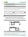
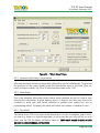
TCG 01 User Manual th 9 Edition: February 2007 6 SPECIFICATIONS 6.1 Dimensions Width Depth Height Weight 160mm 155mm 40mm (1U) 0.8Kg Each TCG 01 unit is supplied complete with antenna, antenna mount, antenna cable and 1U 19” rack-mount hardware. Shipping weight of the complete TCG 01 kit is 4.5Kg. 6.2 Identification Each TCG 01 unit is shipped with an identification label on the base. The label provides details of the particular options fitted to the unit, the power supply requirement, and the serial number. 6.3 Programmable outputs (P2, P3, P4-pin1) The outputs P2, P3, and P4-pin1 are each independently programmable to provide one of the following options. DCF-77 pulse simulation Unmodulated (i.e. DC level-shift) IRIG-B (B00x) Modified Manchester Modulated IRIG-B (B22x) Programmed pulse sequence In the case of “Programmed pulse sequence” above, separate settings are provided so that a differently programmed pulse sequence can be specified for each of the three outputs. Each of the three programmable outputs can also be inverted in its operation. Full details on configuring the programmable outputs are contained in section 6.1 on page 13. N.B: P4-pin1 is not available on TCG 01's with DTE serial ports. If not specified, TCG 01 will ship with a DCE serial port. A common application for the programmable output on P4-pin1 (RS232 level) is to provide an independent drive to an RS232-Fibre converter unit for use in transporting the code signals to a distant location. In such cases, pin 1 should be “broken out” of the normal 9-way cable optionally used to connect to an external PC, and used in conjunction with pin 5 (signal return). Tekron manufactures a range of interface devices (MOFR’s) that includes such converters. Page 13 of 49