1
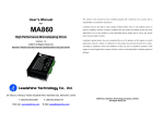
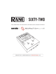
TL - 3012
MEMORY CONTROL CONSOLE
OWNERS MANUAL
Version 0.6
02/17/2005
www.lightronics.com
Lightronics Inc.
509 Central Drive Virginia Beach, VA 23454
TEL 757 486 3588
Page 2 of 6
TL-3012 MEMORY CONTROL CONSOLE
OWNERS MANUAL
Revision 0.6
12/17/2005
SPECIFICATIONS
Channels:
12
Output connector:
3 pin XLR connector
5 pinXLR for DMX-512
Operating modes: Two Scene Manual Mode
Preset Scene Playback Mode
Chase Mode
Compatibility:
Multiplex protocol compatible with
other multiplexed systems
Scene memory:
24 scenes total in 2 banks of 12 each
Power input:
13VAC or +15VDC
Optional external power supply
Chase:
12 programmable 12 step chases
Dimensions:
10.25” W X 9.25” D X 2.5” H
Control protocol:
LMX-128 (multiplex)
Optional DMX-512
Weight:
4.3 Pounds
DESCRIPTION
The TL-3012 is a compact, portable, digital dimmer controller. It provides 12 channels of LMX-128 (industry
standard multiplex) control on a 3 wire cable. It can optionally provide DMX output. The TL-3012 operates in a 2
scene manual mode or can provide 24 preset scenes organized in 2 banks of 12 scenes each. Twelve user
defined chase patterns are always available. Scene fade rate, chase rate and chase fade rate are user
controlled. Audio may also be used as a chase rate control. Other features of the TL-3012 include: a master
fader, momentary buttons, and blackout control. Scenes and chases stored in the unit are not lost when the unit
is turned off.
INSTALLATION
The TL-3012 control console should be kept away from moisture and direct sources of heat. The unit is intended
for indoor use only.
LMX CONNECTIONS: Connect the unit to a Lightronics (or compatible) dimmer using a multiplex control cable
with 3 pin XLR connectors. The TL-3012 is powered by the dimmer(s) which it is connected to. It may also be
powered via an optional external 13 VAC power supply.
DMX CONNECTIONS: Connect the unit to a DMX dimmer using a control cable with 5 pin XLR connectors. The
DMX-512 connection does NOT provide console power therefore an external power supply (provided with units
having DMX option) must be used.
LMX-128 Connector Wiring
(3 PIN FEMALE XLR)
PIN #
1
SIGNAL NAME
Common
2
Phantom power from dimmers
Normally +15VDC
3
LMX-128 multiplex signal
DMX-512 Connector Wiring
(5 PIN FEMALE XLR)
PIN #
1
2
3
4
5
SIGNAL NAME
Common
DMX data DMX data +
Not Used
Not Used
If you are using audio for chase control - ensure that the microphone holes on the back of the unit are not
covered.
You should check the address settings of the dimmers before proceeding with TL-3012 operation.
www.lightronics.com
Lightronics Inc.
509 Central Drive Virginia Beach, VA 23454
TEL 757 486 3588
Page 3 of 6
TL-3012 MEMORY CONTROL CONSOLE
Revision 0.6
OWNERS MANUAL
12/17/2005
CONTROLS AND INDICATORS
MANUAL SCENE Faders:
CROSS FADE:
Control individual channel levels.
Transfers between fader setting and stored scenes. Also used for chase fade
rate control.
COPY MANUAL TO MEMORY: Records fader settings to manual scene memory.
Momentary Buttons:
Activate associated channels at full intensity while pressed. They are also used
for chase selection, prestored scene selection, and scene fade rate selection.
TAP Button:
Press three or more times at desired rate to set chase speed.
TAP Indicator:
Shows the chase step rate.
BLACKOUT Button:
Turns on and off console output from all scenes, channels, and chases.
BLACKOUT Indicator:
Lighted when blackout is active.
MASTER Fader:
Adjusts output level of all console functions.
RECORD Button:
Used to record scenes and chase steps.
RECORD Indicator:
Flashes when chase or scene recording is active.
AUDIO Control:
Adjusts chase sensitivity to internal audio microphone.
AUDIO Indicator:
Indicates that audio chase control is active.
FADE RATE Button:
Allows momentary buttons to be used to set a universal scene fade rate.
CHASE Button:
Allows momentary buttons to be used to select a chase number.
SCENE BANK A and B:
Selects scene bank A or B and enables momentary buttons to be used to select
a scene number within the associated bank.
CHASE FADE RATE:
Reads the CROSS FADER setting as a chase fade rate setting.
TL-3012 FACE VIEW
CROSSFADER
COPY
MANUAL
TO
MEMORY
MANUAL
SCENE
FADERS
CHASE
FADE RATE
AUDIO
MASTER
CHASE
RECORD
FADE RATE
BLACKOUT
SCENE BANK
TAP
MOMENTARY BUTTONS
www.lightronics.com
Lightronics Inc.
509 Central Drive Virginia Beach, VA 23454
TEL 757 486 3588
Page 4 of 6
TL-3012 MEMORY CONTROL CONSOLE
Revision 0.6
OWNERS MANUAL
12/17/2005
OPERATING MODES
The TL-3012 has 3 modes of operation: (1) Two Scene Manual Mode. (2) Preset Scene Mode. (3) Chase
Mode. General operation of the unit in each mode is described below.
Two Scene Manual Mode: Start by moving the “CROSS FADER” up (to the MANUAL position). The upper 12
faders will control the output channels. If you push “COPY MANUAL TO MEMORY” the fader settings will be
copied to a manual scene memory in the unit. At this point you can move the “CROSS FADER” to the MEMORY
position. The channel information is now being provided by memory data which you just copied from the faders.
The 12 upper faders are now free and can be moved without disturbing the output channels since the memory is
now providing the channel output. You can set your NEXT scene on the upper 12 faders. When you move the
“CROSS FADER” back to the MANUAL position - the unit will again take its channel information from the faders.
By proceeding this way you can always create your next scene and then fade to it with the CROSS FADER.
The “COPY MANUAL TO MEMORY” function records at the end of the currently set scene fade rate. You must
leave the “MANUAL SCENE” faders in a stable state for this duration or you may not record the scene correctly.
Preset Scene Mode: In this mode you can activate a series of up to 24 scenes which you have programmed or
preset ahead of time. These scenes are stored in 2 banks of 12 scenes each. This memory is separate from the
memory described in Two Scene Manual Mode operation above. The inter-scene fade rate is controllable and
you can activate the scenes in any desired order. Multiple scenes may be on at the same time (including scenes
from both banks A and B). If multiple preset scenes are on then they will merge in a "greatest of" manner with
respect to individual channels. Specific scene recording and playback instructions are provided in this manual.
Chase Mode: In this mode a series of light patterns is automatically sent to the dimmers. Up to 12 chase
patterns can be created by the operator. Each chase pattern may contain up to 12 steps. The chase step rate
and step fade time may also be controlled. Step times may be set quite long. This will result in what appears to
be an automatic slow scene progression. Specific Instructions for creating and playing chases are provided
further on in this manual. Chases are exclusive (Only one chase may be on at a given time.).
RECORDING PRESET SCENES
1
2
3
4
Adjust the MANUAL SCENE faders to the desired levels (create the scene).
Push “SCENE BANK” to toggle to the desired scene bank (A or B).
Press "RECORD".
Press a momentary button (1 -12) to record the fader settings as a scene.
PRESET SCENE PLAYBACK
NOTE: The “CROSS FADER” must be in the MEMORY position to activate preset scenes.
1 Push “SCENE BANK” button to toggle to the desired (A or B) scene bank.
2 Push the momentary button (1-12) for the scene you want to activate.
PRESET SCENE FADE RATE
The fade rate for preset scenes may be set between 0 and 12 seconds and applies universally to all preset
scenes. The preset scene fade rate may be set at anytime .
1 Push “FADE RATE”. The FADE RATE indicator will light.
2 Push one of the momentary buttons (1-12) to set the rate. The left button is 1 sec.. The right one is 12 secs..
You can set a 0 second fade rate (instant on) by pushing the momentary button which has its indicator lighted.
3 Once you have selected a fade rate - push “FADE RATE”. The FADE RATE indicator indicator will go out and
the unit will return to normal operation.
www.lightronics.com
Lightronics Inc.
509 Central Drive Virginia Beach, VA 23454
TEL 757 486 3588
Page 5 of 6
TL-3012 MEMORY CONTROL CONSOLE
Revision 0.6
OWNERS MANUAL
12/17/2005
RECORDING CHASES
1
2
3
4
5
Press "RECORD". The RECORD LED will begin flashing.
Press "CHASE". This causes the momentary buttons (1-12) to act as chase number selectors.
Press a momentary button (1-12) to select the chase number for recording.
Use the MANUAL SCENE faders to set the channel intensities for the FIRST chase step.
Press "RECORD" to store the settings and advance to the next chase step. The RECORD LED will continue
flashing and the unit is ready to record the next step.
6 Repeat steps 4 and 5 for the next and following steps until all desired steps are recorded (up to 12 steps).
7 Press the momentary button (1-12) for the chase being programmed to end the recording process. If you
record all 12 steps then press the "CHASE" button to end the recording process.
CHASE PLAYBACK
1 Press the "TAP" button 3 or more times at the desired rate to set the chase speed.
2 Press "CHASE". This causes the momentary buttons (1-12) to act as chase number selectors.
3 Press the momentary button (1-12) for the chase you want to activate. The chase will begin running.
The chase step fade time is controllable as follows: While the chase is running - move the CROSS FADER to set
a fade time (0–100% of step duration) then push “CHASE FADE RATE” to read the fader and lock in the rate.
To turn off a chase: Push “CHASE”. The Chase indicator and one of the momentary indicators will be lighted.
Push the momentary button associated with the indicator. The chase will stop and the indicator will go out. Push
“CHASE” to deselect chase setup. The amber chase indicator will go out. The “BLACKOUT” function will inhibit
chases when it is active.
AUDIO DRIVEN CHASE
The chase rate may be controlled by an internally mounted microphone. The microphone picks up sounds nearby
and circuitry in the TL-3012 filters out all but low frequency sounds. The result is that the chase will synchroznize
with base notes of music being played nearby.
Rotate the “AUDIO” control clockwise to increase the sensitivity of the microphone. This control is disabled when
turned fully counterclockwise.
DMX OPERATION
If the DMX option is installed in the TL-3012 it will transmit both DMX and LMX signals simultaneously. The DMX512 connection does NOT provide console power therefore an external power supply (provided with units having
DMX option) must be used.
QUICK START INSTRUCTIONS
The bottom cover of the TL-3012 contains brief instructions for using scenes and chases. The instructions are not
intended as a substitute for this manual and should be viewed as "reminders" for operators who are already
familiar with TL-3012 operation.
www.lightronics.com
Lightronics Inc.
509 Central Drive Virginia Beach, VA 23454
TEL 757 486 3588
Page 6 of 6
TL-3012 MEMORY CONTROL CONSOLE
OWNERS MANUAL
Revision 0.6
12/17/2005
MAINTENANCE AND REPAIR
TROUBLESHOOTING
Check that the multiplex cable is not defective.
To simplify troubleshooting - set the unit to provide a known set of conditions.
Make sure that the dimmer address switches are set to the desired channels.
OWNER MAINTENANCE
The best way to prolong the life of your TL-3012 is to keep it dry, cool, clean, and COVERED when not in use.
The unit exterior may be cleaned using a soft cloth dampened with a mild detergent/water mixture or a mild sprayon type cleaner. DO NOT SPRAY ANY LIQUID directly on the unit. DO NOT IMMERSE the unit in any liquid or
allow liquid to get into the controls. DO NOT USE any solvent based or abrasive cleaners on the unit.
The faders are not cleanable. If you use a cleaner in them – it will remove the lubrication from the sliding
surfaces. Once this happens it is not possible to re-lubricate them.
The white strips above the faders are not covered by the TL-3012 warranty. If you mark on them with any
permanent ink, paint, etc., it is likely that you will be unable to remove the markings without damaging the strips.
There are no user serviceable parts in the unit. Service by other than Lightronics authorized agents will void your
warranty.
EXTERNAL POWER SUPPLY INFORMATION
The TL-3012 may be powered by an external power supply with the following specifications:
Output Voltage:
Output Current:
Connector:
13 to 25 Volts AC or DC
400 Milliamps
2.1mm female connector
NOTE: If a DC power supply is used – the center pin must be the NEGATIVE voltage.
OPERATING AND MAINTENANCE ASSISTANCE
Dealer and Lightronics Factory personnel can help you with operation or maintenance problems. Please read the
applicable parts of this manual before calling for assistance.
If service is required - contact the dealer from whom you purchased the unit or contact Lightronics, Service
Dept., 509 Central Drive, Virginia Beach, VA 23454 TEL: (757) 486-3588.
www.lightronics.com
Lightronics Inc.
509 Central Drive Virginia Beach, VA 23454
TEL 757 486 3588
WARRANTY
All Lightronics products are warranted for a period of TWO/FIVE YEARS from the date of
purchase against defects in materials and workmanship.
This warranty is subject to the following restrictions and conditions:
A) If service is required, you may be asked to provide proof of purchase from an authorized
Lightronics dealer.
B) The FIVE YEAR WARRANTY is only valid if the warranty card is returned to Lightronics
accompanied with a copy of the original receipt of purchase within 30 DAYS of the purchase
date, if not then the TWO YEAR WARRANTY applies. Warranty is valid only for the original
purchaser of the unit.
C) This warranty does not apply to damage resulting from abuse, misuse, accidents, shipping,
and repairs or modifications by anyone other than an authorized Lightronics service
representative.
D) This warranty is void if the serial number is removed, altered or defaced.
E) This warranty does not cover loss or damage, direct or indirect arising from the use or
inability to use this product.
F) Lightronics reserves the right to make any changes, modifications, or updates as deemed
appropriate by Lightronics to products returned for service. Such changes may be made
without prior notification to the user and without incurring any responsibility or liability for
modifications or changes to equipment previously supplied. Lightronics is not responsible for
supplying new equipment in accordance with any earlier specifications.
G) This warranty is the only warranty either expressed, implied, or statutory, upon which the
equipment is purchased. No representatives, dealers or any of their agents are authorized to
make any warranties, guarantees, or representations other than expressly stated herein.
H) This warranty does not cover the cost of shipping products to or from Lightronics for
service.
I) Lightronics Inc. reserves the right to make changes as deemed necessary to this warranty
without prior notification.
Lightronics Inc.
509 Central Drive Virginia Beach, VA 23454
20050125