1
SAMI GS
Frequency converters ACS 501
2.2 to 75 kW
User's Manual
EN 60019134
ASEA BROWN BOVERI
SAMI GS
Frequency Converters ACS 501
2.2 to 75 kW
User's Manual
Code: EN 60019134 C
GSVBC-UML1A1/EN
1995-08-07/EP
v:\markdocu\acs500\usermanu\501\en
1
SAMI GS
Safety Instructions
ONLY A COMPETENT ELECTRICIAN SHOULD
CARRY OUT
THE ELECTRICAL
INSTALLATION
SAMI GS must always be earthed through an
earthing conductor connected to the earthing
terminal.
The Motor Control Card's capacitors contain
dangerous DC voltage levels. After disconnecting the supply, wait at least 5 minutes
after the display readout on the control panel
has disappeared before taking any measurements.
If SAMI GS is connected to a system without
system earth, the earth fault protection must
be capable of starting at earth fault currents
containing high frequency and DC components. SAMI GS' earth fault protection guards
the frequency converter only against earth
faults occuring in the motor or the motor
cable.
Dangerous external control voltages may be
present on the relay outputs of the Control
Interface Card and Option Cards.
Pay attention to the following instructions:
- Do not work on the frequency converter
when power is applied.
Fault current circuit breakers do not necessarily operate properly with frequency converters. Circuit breaker function should be
checked for possible earth fault currents
arising in a fault situation.
- Never connect mains voltage to drive
output terminals (U2,V2,W2).
- Do not make any voltage withstand tests
on any part of the unit. Disconnect motor
cables before taking any measurements
on the motor or motor cables.
Warning symbols
For your own safety please pay special
attention to instructions containing these
symbols.
- Make sure that power factor correction
capacitors are not connected between the
drive and the motor.
Dangerous voltage
- Do not touch the IC-circuits on the Control
Interface and Motor Control Cards. Static
voltage may destroy the circuit.
General warning
ALWAYS CHECK THAT SAMI GS IS SAFE
BY MEASURING THE DC LINK VOLTAGE
AND MAINS INPUT VOLTAGE!
WARNINGS!
SAMI GS contains dangerous voltages when
connected to the mains.
Refer to the figures 5-2, 5-3 on page 18.
Note that the Motor Control Card of the SAMI
GS is at mains supply voltage potential.
2
SAMI GS
Contents
GENERAL
Safety Instructions ................................................................................................... 2
1 How To Use This Manual ..................................................................................... 6
2 Delivery Checks .................................................................................................... 7
3 General Information About SAMI GS .................................................................. 8
INSTALLATION
4 Mechanical Installation ...................................................................................... 11
4.1 Cooling .................................................................................................... 11
4.2 Mounting .................................................................................................. 14
5 Power Connections ............................................................................................ 16
5.1 Mains Cable ............................................................................................. 16
5.2 Motor Cable ............................................................................................. 16
5.3 Insulation Checks .................................................................................... 17
5.4 Terminal Connections .............................................................................. 17
6 Control Connections ........................................................................................... 19
6.1 Control Cables ......................................................................................... 20
6.2 Connections of the Control Interface Card SNAT 7600/7640 ..................... 21
OPERATION
7 Control and Parameter Logic ............................................................................ 22
7.1 Control Panel ........................................................................................... 22
7.2 Control Panel Operation ........................................................................... 22
7.3 Parameter Logic ....................................................................................... 23
7.4 Adjusting Display Contrast ....................................................................... 25
7.5 Operating Data ......................................................................................... 25
7.6 Control ..................................................................................................... 27
3
SAMI GS
7.7 Keypad Control ........................................................................................ 28
7.8 External Control ....................................................................................... 28
7.9 Parameter Lock ....................................................................................... 29
START-UP
8 Commissioning ................................................................................................... 29
8.1 Safety Precautions................................................................................... 29
8.2 Sequence of Operations ........................................................................... 30
8.3 Installation Inspection .............................................................................. 31
8.4 Start-Up Data Parameters ........................................................................ 31
8.5 Checking Selected Application Macro Parameters ................................... 32
8.6 Keypad Control Test Without Motor ......................................................... 32
8.7 Keypad Control Test With Motor .............................................................. 32
8.8 Drive Parameters and Their Factory Settings (Factory Macro). ................ 33
9 Drive Parameters ................................................................................................ 37
9.1 Main 10 - Control Connections ................................................................. 37
9.1.1 Group 11 - Dig/Analog Input Sel .................................................. 37
9.1.2 Group 12 - Analogue Inputs ......................................................... 41
9.1.3 Group 13 - Ref Value Scaling ...................................................... 42
9.1.4 Group 14 - Output Signals .......................................................... 42
9.1.5 Group 15 - Analogue Outputs ...................................................... 44
9.1.6 Group 16 - Out Sig Scaling ......................................................... 45
9.1.7 Group 17 - Ext. Communication .................................................. 46
9.2 Main 20 - Drive ......................................................................................... 48
9.2.1 Group 21 - Acceler/Deceler ......................................................... 48
9.2.2 Group 22 - Freq/Cur Limits .......................................................... 49
9.2.3 Group 23 - Crit Frequencies ........................................................ 50
9.2.4 Group 24 - Const Frequencies .................................................... 51
9.2.5 Group 25 - PI-Controller .............................................................. 51
4
SAMI GS
9.2.6 Group 26 - Start/Stop .................................................................. 55
9.2.7 Group 27 - Motor Control ............................................................. 57
9.2.8 Group 28 - PFC Control .............................................................. 60
9.3 Main 30 - Protection ................................................................................. 65
9.3.1Group 31 - Supervision ................................................................. 65
9.3.2 Group 32 - Fault Function ........................................................... 66
9.3.3 Group 33 - Automatic Reset........................................................ 70
9.3.4 Group 34 - Information ................................................................. 70
SERVICE & MAINTENANCE
10 Fault Tracing & Service .................................................................................. 71
10.1 Fault Indications ..................................................................................... 71
10.2 Fault Resetting ....................................................................................... 71
10.3 Fault History .......................................................................................... 71
10.4 Fault Tracing with a Fault Display .......................................................... 73
10.5 Service ................................................................................................... 80
10.6 Spare parts ............................................................................................ 86
11 Technical Data .................................................................................................. 88
12 Options .............................................................................................................. 90
13 Glossary ............................................................................................................. 91
14 Index .................................................................................................................. 92
5
SAMI
GS
1 How To Use This Manual
The information given in this manual is valid
only for SAMI GS frequency converters.
Short explanations of some less commonly
used technical terms referred to in this
manual are given in the Glossary (pg. 91).
This manual gives instructions for the proper
and safe installation, start-up, operation, fault
tracing and service of SAMI GS frequency
converters.
References to titles of the different sections
of this manual are printed with a capital first
letter. SAMI GS parameter names and
settings are printed in capital letters when
mentioned in the text.
We recommend you read this User's Manual
carefully before starting any installation and
connections or operating your SAMI GS.
Parameters are also referred to by using a
number, which indicates the location of the
parameter (32.1 means the first parameter in
Group 32 of Main 30).
SAMI GS user documentation also includes
an Application Macros Manual, Quick
Reference Guide and Control Panel Operation Instruction sticker, which are included in
the delivery. The sticker is to be placed on
the front cover below the keypad.
Should there be any questions concerning
SAMI GS, please contact the supplier or the
manufacturer.
For quick and easy use of this manual,
please refer to the table of contents on
pages 3 - 5 or index on pages 92 - 93.
The technical data and specifications are
valid at the time of printing. We reserve the
right to subsequent alterations.
ABB Industry Oy
VSD Products
P.O. Box 184
FIN-00381 Helsinki
FINLAND
Telephone: +358-0-5641
Telefax: +358-0-564 2681
Telex: +57-12440502 str fi
6
SAMI
GS
2 Delivery Checks
Note! Do not destroy the packing. The
template printed on the protective cardboard
can be used for marking the fixing points of
the SAMI GS on the wall.
Check that the device does not show any
signs of damage and that the delivery is
complete (refer to the type designation code
presented below). In the event of damage,
please contact your insurance company or
the supplier. If the delivery is not in compliance with the order, please contact the
supplier immediately.
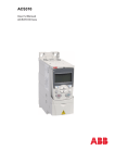
ACS 501-004-3-00P20
If the device is stored before commissioning,
check that the environmental conditions in
the storage room are acceptable (temperature -40 oC to +70 oC; relative humidity < 95%,
no condensation allowed).
The guarantee covers defects in
manufacture. The manufacturer carries no
responsibility for damage occurred during
transport or unpacking.
AC=AC drive
Product type:
S=Standard product
Family:
50=SAMI GS
Under no circumstances shall the
manufacturer be liable for damages and
failures due to misuse, abuse, improper
installation or abnormal conditions of
temperature, dust or corrosives or failures
due to operation above rated capacities.
Nor shall the manufacturer be liable for
consequential and incidental damages.
Sizes:
1=004 to 070, wall
mounted unit
Rated power (kVA)
Supply voltage:
3=380V/400V/415V
5=440V/460V480V//500V
The period of manufacturer's guarantee is
12 months from commissioning and not more
than 24 months from the date of delivery.
Optional Control Card 1:
0=none
3=SNAT 7610 BAC
Local ABB companies or distributors may
have a different guarantee period, which is
specified in their sales terms and conditions
and guarantee terms.
Optional Control Card 2:
0=none, 2=I/O Extension Card
If any queries arise concerning the SAMI GS,
please contact your Distributor or ABB local
office.
Control panel
P=yes
Enclosure class
2=IP 21
5=IP 54
Braking Unit
0=No braking chopper
1=Braking chopper
Figure 2-1. Type designation code.
7
SAMI
GS
3 General Information About SAMI GS
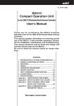
The DC-Intermediate Circuit filters the
pulsating DC-voltage supplied by the
Rectifier Stage.
A Control Interface Card is the link between
the operator and the SAMI. It incorporates a
control panel with an alphanumeric display
and keypad. A terminal block for external
control connections is also located on the
Control Interface Card.
Thanks to the diode bridge, the power taken
from the mains is almost entirely active
power. The power factor approaches unity.
Note! The Control Interface Card
is galvanically isolated from the
mains potential. The card is
connected to earth via a 10 MΩ resistance. If
needed the card can be earthed by connecting with a wire X50 terminal 8 to PE terminal
on the unit frame (see Figure 6-1).
The Inverter Stage forms symmetrical threephase AC-voltage from the constant DCvoltage supplied by the DC-Intermediate
Circuit.
A Motor Control Card controls the Inverter
Stage and monitors the operation of the
SAMI GS.
Note! The maximum permissible
number of charges within one
minute is four. Therefore in
applications where frequent sequential Start/
Stops are required, electronic Start/Stop
should be used, while the unit is powered
continuously.
8
SAMI
GS
Table 3-1.
SAMI GS frequency converter types for 50 Hz and 60 Hz supplies.
Mains voltage 380 V/ 400 V/ 415 V.
Type designation
SAMI's input current I1, output current IN & INSQ and motor power PN & PNSQ
Squared torque applications
Constant torque applications
Rated Rated Short term Max
input
output overload
rated
current current current 1) motor
I 1 /A
IN/A
A
PN/kW
Rated Rated Short term
Max
input
output overload rated
current current current 1) motor
I 1SQ/A
I NSQ /A
A
PNSQ/kW
ACS501-004-3
4.7
6.2
9.3
2.2
6.2
7.5
8.3
3.0
ACS501-005-3
6.2
7.5
11.3
3.0
8.1
10.0
4.0
8.1
11.0
10.0
15.0
4.0
13.2
19.8
5.5
27.0
7.5
21.0
18.0
24.0
19.8
15.0
13.2
18.0
11.0
15.0
11.0
14.5
26
7.5
11.0
ACS501-016-3
21.0
24.0
34
15.0
31.0
11.0
15.0
31.0
28.0
36.0
46.5
28.0
ACS501-020-3
34.0
39.0
43
18.5
ACS501-025-3
34.0
39.0
58.0
18.5
41.0
47.0
22.0
ACS501-030-3
41.0
47.0
70.5
22.0
62.0
ACS501-041-3
ACS501-050-3
55.0
93.0
30.0
114
37.0
85.0
76.0
89.0
84
72.0
62.0
76.0
55.0
67.0
52
68
98.0
37.0
45.0
ACS501-060-3
85.0
89.0
134
45.0
101
112
123
55.0
ACS501-006-3
ACS501-009-3
ACS501-011-3
Table 3-2.
5.5
30.0
SAMI GS frequency converter types for 50 Hz and 60 Hz supplies.
Mains voltage 440 V/ 460 V/ 480 V/ 500 V.
Type designation
SAMI's input current I1, output current IN & INSQ and motor power PN &PNSQ
Constant torque applications
Squared torque applications
Rated Rated Short term Max
input
output overload rated
current current current1) motor
IN/A
A
PN/kW
I 1 /A
Rated Rated Short term Max
input
output overload rated
current current current1) motor
A
PNSQ/kW
I 1SQ /A I NSQ/A
ACS501-005-5
4.7
6.2
6.2
7.5
8.3
4.0
ACS501-006-5
7.5
9.3
11.3
3.0
6.2
4.0
8.1
10.0
11.0
5.5
ACS501-009-5
8.1
10.0
15.0
13.2
11.0
13.2
19.8
5.5
7.5
11.0
ACS501-011-5
15.0
18.0
14.5
19.8
11.0
ACS501-016-5
15.0
21.0
18.0
27.0
11.0
21.0
24.0
26
36.0
15.0
18.5
31.0
39.0
15.0
18.5
43
22.0
ACS501-030-5
35.0
39.0
46.5
58.0
28.0
35.0
34
28.0
24.0
31.0
22.0
41.0
47.0
52
30.0
ACS501-041-5
41.0
47.0
70.5
55.0
58.0
55.0
58.0
87.0
63.0
65.0
64
72
37.0
ACS501-050-5
30.0
37.0
ACS501-060-5
63.0
81.0
65.0
97.5
45.0
81.0
84.0
93
55.0
84.0
126
55.0
101
112
123
75.0
ACS501-020-5
ACS501-025-5
ACS501-070-5
1)
Allowed for one minute every ten minutes.
9
7.5
45.0
SAMI
GS
Mains connection
Brake connection
Motor connection
U in
U out
PE
IU
Power
supply
PE
DC
Measurements
Gate
drivers
T
Inverter control
Motor
control
Control
Communication
interface
with Motor control
X56
X51
Comm. with
PC,PLC etc.
Application control
X55
2
X53
progr.
Analog
Inputs
6
progr.
Digital
Inputs
X50
Figure 3-1. SAMI GS block scheme.
10
2
progr.
Analog
Outputs
3
progr.
Relay
Outputs
SAMI GS
4 Mechanical Installation
SAMI GS is mounted on a wall in a vertical
position using four fixing notches at the top
and bottom of the unit. When choosing the
mounting location pay attention to the cooling needs of the SAMI GS.
4.1 Cooling
SAMI GS frequency converters are provided
with a cooling fan(s) on the bottom of the unit.
The ambient operating temperature for
constant torque drives, when the load current
fS = 3
is (IN) and switching frequency
kHz, is 0 ... 45 oC, except for ACS 501-006-3
and 009-5 0 ... 40 oC. See fig. 4-2 output
current derating curves.
The
ambient operating temperature for squared
torque drives, when the load current is (INSQ)
and switching frequency fS = 3 kHz, is 0 ... 40
o
C, except for ACS 501-006-3 and 009-5 0 ...
35 oC. See fig. 4-2 output current derating
curves.
If the cooling ability is reduced too much, the
thermal protection operates causing a fault
indication and stopping the frequency converter. SAMI GS can be started again when
the temperature of the cooling element has
fallen below the tripping level*) (+70 oC).
The temperature of the cooling element can
be read from the control panel display
(Oper- ating Data, parameter 8, SAMI
TEMPERATURE).
for types ACS 501-050-3, 060-3, 060-5 and
070-5, the tripping level is +75 oC.
*)
The cooling air must be clean and free from
corrosive materials. Where necessary the
cooling air should be filtered.
If the cooling air contains dust, clean the
cooling surfaces of the unit regularly using
compressed air and a brush.
Table 4-1. Required cooling air.
Type ACS 501004-3...006-3,
005-5...009-5
009-3, 011-3, 011-5, 016-5 102
016-3, 020-3, 020-5, 025-5 406
025-3...060-3,
030-5...070-5
[m3/h]
51
560
11
SAMI GS
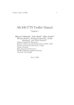
Figure 4-1. Power dissipation as a function of
the switching frequency for different ACS 501
types. Output power in the following curves is
P NSQ.
P l o s s 600
[W]
500
-011-3
-016-5
400
-009-3
-011-5
300
-006-3
-009-5
200
-005-3
-006-5
100
-004-3
-005-5
3 4 5 6 7 8 9 10 11 12
f [kHz]
P l o s s 2750
[W] 2500
-060-3
-070-5
-050-3
-060-5
-041-3
-050-5
-030-3
-041-5
-025-3
-030-5
-020-3
-025-5
-016-3
-020-5
2000
1500
1000
500
16-70HAV.DRW
3 4 5 6 7 8 9 10 11 12
f [kHz]
Figure 4-2. Output current derating curves as
a function of ambient temperature and
switching frequency.
II
ACS 501
-006-3 I NSQ
-009-5 I NSQ
-005-3 I NSQ
-006-5 I NSQ
-006-3 IN
-009-5 IN
-004-3 I NSQ
-005-5 I NSQ
-005-3 IN
-006-5 IN
oout
ut
[A]
[A]
15
12 kHz
10
3 kHz
5
-004-3 IN
-005-5 IN
10
20
12
30
40
50T a m b Tamb
[°C]
[oC ]
SAMI GS
I out
out
[A]
ACS 501
-011-3
I NSQ
-016-5
I NSQ
-009-3
I NSQ
-011-5
I NSQ
-011-3 IN
-016-5 IN
30
12 kHz
3 kHz
20
10
-009-3 IN
-011-5 IN
10
I out
[A]
20
30
40
40
ACS 501
-020-3
I NSQ
-025-5
I NSQ
-016-3
I NSQ
-020-5
I NSQ
-020-3 IN
-025-5 IN
30
20
10
30
40
50
T amb
[ o C]
120
3 kHz12 kHz
100
-060-5
I NSQ
-070-5 IN
80
IN
20
I out [A]
-050-3
I NSQ
-060-3 IN
-050-3
-041-3
I NSQ
-060-5
-050-5
I NSQ
-030-3
I NSQ
-041-3
-041-5
I NSQ
-050-5
-025-3
I NSQ
-030-5
I NSQ
T amb
[ oC]
3 kHz
12 kHz
-016-3 IN
-020-5 IN
ACS 501
-060-3
I NSQ
-070-5
I NSQ
50
3 kHz
12 kHz
60
IN
40
25-70LOA.DRW
IN
IN
10
13
20
30
40
50
T amb
[ oC]
SAMI GS
4.2 Mounting
Cooling air outlet
d (see table
below)
SAMI GS
50 mm
50 mm
Note! Do not handle or lift the drive using the
front cover. Use the bottom part for handling.
To ensure safe installation, check that the
surface mounting is flat. Mark the fixing points
of SAMI GS on the wall using the template
printed on the protective cardboard package
as a guide. The maximum size of the fixing
screws is 6 mm (15/64") for ACS 501-0043...006-3 and ACS 501-005-5...009-5 units and
8 mm (5/16") for 009-3...060-3 and 016-5...0705 units.
Fix the screws to the marked positions.
Attach the unit by the fixing notches and
tighten the screws.
Cooling air
inlet
Type
ACS 501-004...011-3
ACS 501-005...016-5
ACS 501-016...060-3
ACS 501-020...070-5
Note! If multiple units are installed adjacent
or above each other, the following minimum
distances apply:
- units side by side, clearance 100 mm - units
above each other, clearance 300 mm
50 mm
d/[mm]
150
150
250
250
Figure 4-3. Space requirement for adequate
cooling.
14
SAMI GS
L
a
b
L1
H
H1
H2
c
D
L
L1
H
H1
H2
D
a
b
c
Weight
/kg
ACS501004...006-3
ACS501009...011-3
ACS501016...020-3
ACS501025...041-3
ACS501050, 060-3
005...009-5
(mm)
200
150
362
350
312
188
7
14
7
011...016-5
(mm)
250
175
425
400
380
208
9
18
9
020...025-5
(mm)
300
225
507
480
460
249
9
18
9
030...050-5
(mm)
350
275
603
575
551
262
9
18
9
060, 070-5
(mm)
350
275
603
575
551
307
9
18
9
abt. 12
abt. 22
abt. 36
abt. 40
abt. 7.2
Figure 4-4. Dimensions of the SAMI GS unit. (Drawing presents 004...006-3)
15
SAMI GS
5 Power Connections
5.1 Mains Cable
SAMI GS is rated for a 380 V/400 V/415 V or
440 V/460 V/480 V/500 V 3-phase system.
A 4-conductor screened cable (three phase
with Protective Earth) is recommended for the
mains cabling. The cables and fuses are to
be dimensioned in accordance with the output current. See Table 5-1 for minimum dimensions. When dimensioning cables, always pay attention to local authority regulations.
Note! Remove all the compensation capacitors from the line side so that
they are not powered up at the same time as
the SAMI GS.
5.2 Motor Cable
A 4-conductor screened cable is recommended due to the rapid voltage changes
occurring in variable frequency motor drive
systems.
To avoid disturbances
Install the motor cable away from other cable
routes. Avoid long parallel runs with other cables (see page 20).
Disturbances caused by radiation from the
motor cable can be reduced by mounting
chokes in the motor cable. These chokes
may reduce the motor voltage and the maxiThe rapid voltage changes cause capacitive current through the motor cable stray capacitances. This current rises as the switching frequency and cable length increase.
This phenomenon can cause substantially
higher current measured by the SAMI GS
than the actual motor current, and can cause
overcurrent tripping. This means that when
Table 5-1. Mains & motor cables and fuse recommendations according to output current (IN, INSQ).
Type
ACS 501-
IN
(A)
Fuse
(A)
Cu-cable
(mm2)
I NSQ
(A)
Fuse
(A)
Cu-cable
(mm2)
Max. Cable (Cu or Al)
(mm2)
004-3/005-5
005-3/006-5
006-3/009-5
009-3/011-5
011-3/(016-5)
016-3/020-5
020-3/025-5
025-3/030-5
030-3/(041-5)
041-3/(050-5)
050-3/(060-5)
6.2
7.5
10.0
13.2
18.0
24.0
31.0
39.0
47.0
62.0 (58.0)
76.0 (65.0)
10
10
10
16
25
25
35
50
50
63
80
3*1.5+1.5
3*1.5+1.5
3*1.5+1.5
3*2.5+2.5
3*6.0+6.0
3*6.0+6.0
3*10+10
3*16+16
3*16+16
3*25+16
3*35+16
7.5
10.0
13.2
18.0
24.0 (26.0)
31.0
39.0
47.0
62.0 (58.0)
76.0 (65.0)
89.0 (84.0)
10
10
16
25
25
35
50
50
63
80
100
3*1.5+1.5
3*1.5+1.5
3*2.5+2.5
3*6.0+6.0
3*6.0+6.0
3*10+10
3*16+16
3*16+16
3*25+16
3*35+16
3*50+25
3*2.5+2.5
3*2.5+2.5
3*2.5+2.5
3*6.0+6.0
3*6.0+6.0
3*10+10
3*16+16
3*35+16
3*35+16
3*35+16
3*70+35
060-3/(070-5)
89.0 (84.0)
100
3*50+25
112
125
3*70+35
3*70+35
Table 5-2. Maximum recomm. length of the motor cable in accord. with switching frequency.
Switching
frequency
[kHz]
1
75
12
004...011-3/005...016-5
016-3...020-3/020...025-5 025-3...060-3/030-5...070-5
Screened Unscreened Screened Unscreened Screened Unscreened
cable [m] cable [m]
cable [m] cable [m]
cable [m] cable [m]
100
100 150
200
250
50
75
75
100
150
200
16
SAMI GS
cable lengths given in Table 5-2 are exceeded for types ACS 501-004...011-3 or ACS 501005...016-5, the output choke should be used.
Note! To avoid interference problems in
control cables all the cabling should be
screened and should not run parallel to the
motor cables (see page 20 for minimum distances).
B
IP 21 types:
A
ACS 501-016...060-3, ACS 501-020...070-5
and all types as IP 54 construction, except
ACS 501-009-3, 011-3, 011-5 and 016-5.
mum available torque. If noise problems exist, contact ABB for more detailed
information.
5.3 Insulation Checks
Note! Insulation checks must be performed
before connecting the SAMI to the mains.
Before proceeding with the insulation resistance measurements make sure that the
SAMI is disconnected from the mains.
1. Check that the motor cable is disconnected from the SAMI output on terminals
U2, V2 and W2.
2. Check that the motor cable is disconnected from the motor and remove bridging connections at the motor.
3. Measure the insulation resistances from
the motor. The voltage range of the
insulation resistance meter must be at
least equal to the mains voltage, but not
exceeding 1000 V. The insulation resistance must be greater than 1 MΩ.
4. Measure the insulation resistance of the
motor cable between the phases and
between each phase and Protective
Earth. The insulation resistance must be
greater than 1 MΩ.
5.4 Terminal Connections
B
IP 54 types:
ACS 501-009-3, 011-3, 011-5 and 016-5.
A
B
Figure 5-1. Installation of the cable entry
insulator.
To connect the power, motor and control
cables, remove the front cover of the unit by
removing the four screws at the corners of
the cover. Then remove the front part of the
cable entry insulator by removing the screws
(A) at the ends of the insulator. Remove the
protective caps of the cable entry holes
using a knife or a screwdriver.
In order to make the cable installation easier,
the cable entry insulator can be removed as
one piece by unscrewing the screws (B) and
pulling the insulator off the frame.
17
SAMI GS
Connect the power cables in accordance with the following drawings. Attach the front part of
the cable entry insulator with the screws (A) and attach the front cover of the unit by the four
screws.
ACS 501
Motor
PE connection
X3
U2
V2
V1
U1
W2
Mains
connection
X2
X1
+ -
U1
V1 W1
W1
3
Motor
Figure 5-2. Standard Unit.
PE
L1
L2
L3
Mains
ACS 501
Motor
PE connection
X3
U2
U1
V2
V1
W2
W1
3
Motor
Figure 5-3.
Unit with internal Braking Chopper.
Brake Resistor
connection
Mains
connection
X2
X1
R+ R-
R+
R-
U1
V1 W1
L1
L2
PE
Brake
Resistor
(option)
PE
L3
Mains
WARNING!
The brake control terminals carry a dangerous DC voltage (>500V).
Only an ABB dynamic braking device should be connected to terminal X2.
Note! If the motor cable has a separate screen in addition to the earth wire, the
screen is connected to the PE terminal at the frequency converter end and on the
motor side.
18
SAMI
GS
6 Control Connections
X57
X56
X54
X60
TERM NO
S3S4
1
X55
NO
S4S3
7
X51
I
U
S1S2
K1
S2S1
K2
K3
X50
X53
11
2 3 4 5 6 7 8 9 1011 121314 151617 181920
212223
242526
32272829
Figure 6-1. Control Interface Card SNAT 7640.
The Analogue Input signal selection is done with jumpers S1 (AI1) and S2 (AI2):
I = 0(4) - 20mA, V = 0(2) - 10V.
X50 = screw terminal, X53 = earthing connector, X54 = connection to Motor Control Card,
X55 and X56 = option card connectors.
X51 for RS 485 connection. Jumpers S3 and S4 are set to TERM in the last SAMI GS unit of a
RS 485 chain.
The available control places for SAMI GS
are:
diagrams for Application Macros are presented in the Application Macro Manual.
a) Keypad (see Section 7, page 22)
The X50 connection diagram based on
factory settings is presented in Section 6.2 on
page 21. The terminal functions can be
altered by means of parameter settings (refer
to Section 9).
b) The X50 screw terminal on the Control
Interface Card SNAT 7600/7640 in the
Control Unit.
c) The RS 485 serial communication bus;
terminals X51 on Control Interface Card.
Some basic functions are selected by setting
the jumpers on the Control Interface Card.
Refer to Figure 6-1.
External control devices, for example a PLC
or a remote control panel SACE 11 PAN,
are connected to the screw terminal X50
according to the connection diagram of
each Application Macro. The connection
The Control Interface Card is accessible after
removing the front cover of the SAMI GS.
19
SAMI
GS
6.1 Control Cables
must be protected by using varistors or RC
units (AC) or a diode (DC). The protection
components should be installed onto the coil
of the relay or contactor being controlled and
not on the terminals of X50. When using an
RC unit, note that the leakage current of the
RC circuit must be less than the holding
current of the controlled contactor or relay.
Control cables for the SAMI GS should be
0.5 - 1.0 mm2 screened, multi-core cables.
The cable screens should be earthed at the
PE of the frequency converter chassis.
When planning the cabling between the
SAMI GS and an automation device, such as
a PLC, attention should be given to interference suppression, signal levels, galvanic
isolation, etc. These cables should be
separated from the mains and motor cables
and not running in parallel with them (minimum separation 300 mm if parallel run
< 10 m; add 300 mm for every 10 m). There
should be no additional control components
(contactors or relays) inside the SAMI GS
and no control cables other than those of the
SAMI GS.
The control connections of the SAMI GS are
galvanically isolated from mains potential
and have a 10 MΩ resistance from the
inverter frame i.e. PE. Because of this, there
is no need to connect X50/2,4,6 and 8 (logic
GND) to TE or PE. However, it could prove
useful to do this if EMC problems occur.
Analogue input and output signals:
A separate twisted pair must always be used
for each individual signal.
Digital inputs:
It is strongly recommended to use screened
cables for digital inputs (DI). An external
+24V supply for the digital inputs (DI1 to DI6)
must not be used.
Relay outputs:
If relay outputs (RO) operate on 24 V DC, the
signals can be routed to the same cable
used for the digital inputs. If twisted cables
are used, digital output and input should
never be in the same pair. If 110 V/230 V AC
is connected to a relay output, a separate
cable without screen can be used for these
signals.
Note! If the relay outputs are used to control
inductive loads (e.g. relays, contactors) they
20
SAMI
GS
Note! Do not use external voltage
supply to control the digital inputs.
6.2 Connections of the Control Interface Card SNAT 7600/7640
(factory settings).
Hz
A
Ready
Run
Fault
230V
AC
see page 47
Terminal X50
1
REF
2
GND 2
3
AI 1+
4
AI 15
AI 2+
6
AI 27
SPL
8
GND 2
9
N.C.
10
SPL
11
DI 1
12
DI 2
13
DI 3
14
DI 4
15
DI 5
16
DI 6
17
AO 1+
18
AO 119
AO 2+
20
AO 221
RO 11
22
RO 12
23
RO 13
24
RO 21
25
RO 22
26
RO 23
27
RO 31
28
RO 32
29
RO 33
Terminal X51
1
+8 V
2
GND2
3
SCRN1
4
GND3
5
SGNA
6
SGNB
7
SCRN2
Function
Reference voltage 10 V DC
max. 10 mA 1 kΩ < R < 10 kΩ
Reference signal
0 V - 10 V or 0 mA - 20 mA 1)
Not specified in this application
2 V - 10 V or 4 mA - 20 mA 1)
Aux. voltage output 24 V DC
max. 200 mA (total of term. 7&10)
Not connected
+24 V max. 200 mA (tot. of 7&10)
START/STOP
Direction
Constant speed selection 2)
Constant speed selection 2)
Not specified in this application
Acceleration/Deceleration 1 or 2
Output frequency
0 ... 20 mA <-> 0 ... 50 Hz
Motor current
0 ... 20 mA <-> 0 ... IN
Relay output 1
READY indication
Relay output 2
RUN indication
Relay output 3
FAULT indication
Function
Power to remote panel
RS 485 serial link connections
1) Select voltage or current reference with jumpers S1 and S2 on the Control Interface Card
(located besides the terminal X51).
2) Refer to parameter 11.7. CONST SPEED SEL on page 40.
21
SAMI
GS
7 Control and
Parameter Logic
7.1 Control Panel
Main name
DRIVE
20 MAIN
I]
Main number
The control panel, situated on top of the
Control Interface Card, incorporates a 2 by
20 character, alphanumeric LCD and a
keypad.
Rotation direction
-->
forward
<-reverse
The operational information, parameters, as
well as fault indications are displayed in nine
languages*): English, Finnish, Swedish, German, Dutch, French, Danish, Spanish and
Italian. The language selection is made in
Start-Up Data Group parameter A LANGUAGE (refer to page 31).
*) Factory setting is English.
R1[ -->
Control place
[ ]
Keypad
External
Run status
I = Run
0 = Stop
7.2 Control Panel Operation
Panel keys
Parameter number
and name
2
[
Active reference
R1=Ref 1 R2=Ref 2
ACCELER TIME 1
30 s
] R1[ -->
Parameter value
Selects the Setting mode and saves
the selected parameter value.
I]
Selects Operating Data as well as
Main, Group and Parameter levels. In
Setting mode, returns to the Display
mode without changing the Parameter value.
In Display mode selects the next/
previous Main, Group or Parameter.
In Setting mode increases/decreases parameter value.
Mode indication
[ ]
Setting mode
Display mode
Changes the rotation direction in
Keypad control (refer to parameter
11.8 on page 40).
Figure 7-1. Control panel displays. Note that
all the indications may not be visible at the
same time.
Starts and stops the motor in Keypad
control. Resets faults, warnings and
supervision indications.
Note! To accelerate the rate of change of
parameter value, keep the
or
button depressed continuously.
22
SAMI
GS
7.3 Parameter Logic
Note! When the power is switched on, the last parameter displayed before the unit was
switched off is displayed except for Start-up Data parameters (SAMI OUTPUT FREQ will be
displayed).
1
Start-up Data:
A
B
C
D
E
F
G
H
Language
Application
Applic. Restore
Supply Voltage
Pole Number
Motor nom Current
Motor nom Power
Cos phi of Motor
4
4
16
14
13
Operating Data:
12
11
10
20
3
5
3
15
+
1 SAMI Output Freq
2 Motor Speed
3 Motor Current
.
.
.
2
5
2
1
Parameter
Group
30
Main
23 Parameter Lock
Figure 7-2. The parameters are divided into 3 Main and 19 Groups according to their function.
In addition there are Operating Data parameters and Start-Up Data parameters.
Start-up Data are application and motor specific , which must be entered during commissioning.
The Operating Data display monitors values from the drive. Control place and parameter lock
selection is made in this mode.
A complete table of parameters is presented on pages 33 - 36.
23
SAMI
GS
Figure 7-3. Example of control panel operation:
Let us suppose that you want to set the parameter 22.1 MINIMUM FREQUENCY to 3Hz. The
following example explains the procedure.
1
SAMI OUTPUT FREQ
45.5 Hz
R1[ --> I ]
Press to Main level
CONT CONNECTIONS
10 MAIN
R1[ --> I ]
Select the required Main level
or
DRIVE
20 MAIN
R1[ --> I ]
Press to Group level
ACCELER/DECELER
21 GROUP
R1[ --> I ]
Select the required Group
or
FREQ/CUR
22 GROUP
LIMITS
R1[ --> I ]
Press to Parameter level
1
1
[
Select the required Parameter
by
and
keys
MINIMUM FREQUENCY
5 . 00 Hz
R1[ --> I ]
Change to Setting mode
Brackets indicate that the
parameter value can now be
changed
MINIMUM FREQUENCY
5 . 00 Hz
] R1[ --> I ]
Set the parameter value
1
[
MINIMUM FREQUENCY
3 . 00 Hz
] R1[ --> I ]
1
MINIMUM FREQUENCY
3 . 00 Hz
R1[ --> I ]
To cancel the change and return
to Display mode, press
Save the selected value to
permanent memory
Brackets disappear indicating
that the parameter value is
stored in memory
Return to Operating Data
parameter 1 SAMI OUTPUT
FREQ
1 SAMI OUTPUT FREQ
45.5 Hz
R1[ --> I ]
24
SAMI
GS
7.4 Adjusting Display Contrast
The contrast of the LCD can be adjusted for
optimal viewing. This can be done when the
display is at Main or Group level.
To adjust contrast, hold down
press
or
and
.
It may be necessary to adjust the display
contrast if the SAMI has been installed in a
location with high ambient temperatures.
The factory default setting is optimum for an
ambient temperature between 15 oC and
30 oC.
Running data and keypad control parameters
A complete description of the parameter Groups is given in chapter 9, Drive parameters.
Operating Data parameters are described here.
7.5 Operating Data
The monitored values are updated five times a second. The accuracy figures given in brackets are valid for steady state signals. Actual reference signal is shown once a second if the
frequency converter is stopped. Note! If measured value goes beyond the range of the
parameter, expression marks ("!!") are shown on the display.
Parameter
Range/Unit
Description
1 SAMI Output Freq
Hz
Frequency to motor
2 Motor Speed
rpm
Actual (encoder)/calculated motor speed
3 Motor Current *)
A
Motor current (+ 5 %)
4 Calcd Torque/Tn
%
5 Calcd Power/Pn
%
Calculated motor torque,100 = TM (+ 15
%)
6 DC-Voltage
V
7 SAMI Output Volt
V
8 SAMI Temperature
9 Control Place
o
Calculated motor power, 100 = PM (+ 15
%)
TM and PM correspond to the motor data
given in para. E and G of Start-up group
Intermediate circuit DC-voltage
C
Calculated motor voltage (+ 5 %)
Keypad R1/
Temperature of the heatsink
Keypad R2/External
* ) This parameter indicates small current value even though the motor cables and the motor
is not connected.
25
SAMI
GS
Operating Data continued:
Parameter
Range/Unit
10 Keypad Ref 1
Hz
11Keypad Ref 2
%
12 Ext Ref 1 or 2
Control place selection (R1 = Reference
1)
(R2 = Reference 2)
Ref1/Ref2
13External Ref 1
Hz
14External Ref 2
%
15 Appl Block Output
Hz
16 Actual Value 1*)
%
17 Actual Value 2*)
%
18 Op-Hour Counter
h
19 kWh Counter
Description
Frequency reference from control panel
Controller reference from control panel
External control place selection
External frequency reference
External controller reference
Controller output signal
Feedback signal for the PI-controller
kWh
Feedback signal for the PI-controller
20 Last-Recd Fault
-
21 Second-Recd Fault
-
22 First-Recd Fault
-
23 Parameter Lock
Open xxx/Locked xxx
Operation hour counter
kWh counter
The latest fault indication (refer to p. 71)
The previous fault indication
24 Aux Motrs running**)
number
25 Controller Output**)
%
Parameter software lock (xxx code = 358)
26 Controller deviation**)
%
Number of running constant speed
(mains connected) motors
The oldest fault indication
Output value of PI regulator. Values in %
of regulation range.
27 Act value 1 (PFC)**)
units
28 Act value 2 (PFC)**)
units
Deviation of PI regulator in % of regulation range including sign (+ if ACT > REF,
- if ACT < REF)
Unscaled actual feedback signal no. 1 in
units set with parameter 28.30
*)These parameters are only displayed if the PI- or PFC-Control macro is selected.
Unscaled actual feedback signal no. 2 in
**)These parameters are displayed only if PFC-Control
macro
is selected.
units
set with
parameter 28.30
26
SAMI
GS
7.6 Control
The SAMI GS can be controlled from two external control places or from the Control Panel
Keypad (Fig. 7-5 on page 28). The Figure below presents the standard control signal selecCONTROL PLACE
9
KEYPAD R1
1
KEYPAD R2
2
EXTERNAL
3
How to set reference:
1
KEYPAD REF 1
10
KEYPAD REF 2
11
3
CONST FREQUENCIES
R1
EXTERNAL REF 1
SEL 11.5
KEYPAD AI1,AI2
D3U,4D(R) DI3U,4D
DI5U,6D
AI1JOYST
STD COMMU *)
CRIT FREQUENCIES
2
1: 24.1
2: 24.2
3: 24.3
4: 24.4
1
2
3
EXTERNAL REF 2
SEL
11.6
ACC/DEC REF 2 T.
R2
21.6
21.7
0-1800s 0-1800s
APPLICATIONS:
PI-Control Gr. 25
PFC-Contr. Gr. 28
Speed Ctrl. Gr. 29
KEYPAD AI1
D3U,4D(R) AI2
DI3U,4D
DI5U,6D
ACTUAL 1 INPUT
25.7 or 28.22
NO
AI1
AI2
STD COMMU
2
1
3
1: 23.2
2: 23.4
3: 23.6
4: 23.8
5: 23.10
ACC/DEC TIME 1
21.2
21.3
0.1-1800 s 0.1-1800 s
ACC/DEC RAMP
SHAPE 21.1
LINEAR
ACC/DEC TIME 2
21.4
21.5
0.1-1800 s 0.1-1800 s
S1-SHAPE
S2-SHAPE
S3-SHAPE
ACC/DEC 1 OR 2 SEL
11.10
NOT SEL
DI1 ... DI6
MINIMUM FREQUENCY
22 . 1
0 ... 120/500 Hz **)
MAXIMUM FREQUENCYREF
22.2
0 ... 120/500 Hz **)
MAX. FREQ. RANGE
22.4
0...120
0...500 Hz
ACTUAL 2 INPUT
25.8 or 28.23
NO
23.3
23.5
23.7
23.9
23.11
CRIT FREQ SEL.
23.1
ON
OFF
CONST SPEED
SEL
11.7
NOT SEL
DI1 DI2 DI3
DI4 DI5 DI6
DI1,2
DII,2,3
DI3,4
DI3,4,5
DI5,6
DI4,5,6
EXT CONT PLACE
SEL
11.2
KEYPAD
DI1
DI2
DI3
DI4
DI5
DI6
STD COMMU *)
STD COMMU *)
5: 24.5
6:24.6
7: 24.7
1
AI1
How to set operation controls:
AI2
1
2
KEYPAD
CONTROL
EXT1 I/O
CONTROL SEL
11.3
EXT2 I/O
CONTROL SEL
11.4
NOT SEL DI1
DI6
DI1,2
DI1P,2P
DI1P,2P,3
DI1P,2P,3P
DI6,5
STD COMMU *)
RUN ENABLE
11.1
R1
R2
DIRECTION
11.8
CTRLs
REVERSE
FORWARD
REQUEST
FAST REV
*) OPT COMMU selection added when an optional
communication card is connected.
**) max value selected with parameter 22.4 (see also group 13, page 42)
Note! Additional selections provided by I/O Extension Card are described in the Option card manual.
REF 1 & 2 LIMITS, INVERT AND FILTER, SEE SEP. DIAGR.
12.1 - 12.6, 13.1 - 13.4
13 EXTERNAL REF1
(KEYPAD)
13 EXTERNAL REF1
(DIGITAL INPUT)
Analogue I/O configuration:
Y E S DI1
DI2
DI3 DI4
DI5
DI6 STD COMMU
AI1 JOYST.
TERM. 3&4
3
FILTER AI1
12.1
0.01 ... 10 s
MINIMUM AI1
12.2
0V/0mA/2V/4mA
INVERT AI1
12.3
NO
YES
FILTER AI2
12.4
0.01 ... 10 s
MINIMUM AI2
12.5
0V/0mA/2V/4mA
INVERT AI2
12.6
NO
YES
14 EXTERNAL REF 2
(KEYPAD)
14 EXTERNAL REF 2
(DIGITAL INPUT)
LOHKOA_ D.DRW
EXTERNAL REF 1 SEL
11.5
EXT REF 1 MIN
SCALE 13.1
0 - 120/500 Hz **)
EXT REF 1 MAX
SCALE 13.2
0 - 120/500 Hz **)
EXT. REF 1
EXT REF 2 MIN
SCALE 13.3
0 - 120/500 Hz **)
EXT REF 2 MAX
SCALE 13.4
0 - 120/500 Hz **)
EXT. REF 2
EXTERNAL REF 2 SEL
11.6
Figure 7-4. Standard control signal selections. The software switches in the diagram are set
either by parameter or digital inputs, as indicated in the box at the end of the dashed line.
27
SAMI
GS
tions.
the frequency reference, select parameter 10
KEYPAD REF1, press the
key and
use the
and
keys to increase
or decrease the keypad reference.
Select Operating Data parameter
9, CONTROL PLACE, KEYPAD R1/
KEYPAD R2 for keypad control (Control
place is Ref 1 or Ref 2 accordingly) or
EXTERNAL for external control. The valid
control place is indicated on the display.
[ ] around the direction and run indicators
means keypad control and without [ ] means
When in keypad control using reference 1,
it is possible to change the keypad reference value while monitoring any of the
measured values 1-8. For example, you can
monitor parameter 7, SAMI OUTPUT VOLT
while changing the frequency. To do this,
select the measured value you prefer, press
key and set the reference frequency
with
and
keys.
Keypad control
(R1 or R2)
External control
for example a PLC
(automatic)
External control
(manual)
If the SAMI GS is running with an external
reference and the CONTROL PLACE is
changed to KEYPAD R1, it is possible to
transfer the current value of the external
reference to KEYPAD REF1.
12345678901
12345678901
12345678901
12345678901
Example: The SAMI GS is receiving a frequency reference from a transducer via X50.
You want to temporarily override the external
frequency reference. Select CONTROL
PLACE, KEYPAD R1 and press
and
. The SAMI GS puts the value of the
external reference into KEYPAD REF1. You
may now control the drive manually by
KEYPAD REF1.
R1
R2
external control. In addition R1 means Ref 1
and R2 Ref 2 (Figure 7-1).
Figure 7-5. Control places.
If you enter Display mode by pressing
after selecting CONTROL PLACE, KEYPAD
R1, the value of parameter KEYPAD REF1
will be the set MINIMUM FREQUENCY.
7.7 Keypad Control
When Keypad R1 or Keypad R2 is selected
from Operating Data parameter 9, SAMI GS
will operate according to the commands
which are given via the Keypad.
Keypad Reference 2
Keypad Reference 2 goes through an
application block, where it can be manipulated. Keypad Reference 2 can be used as
a controller reference and it can be given its
own acceleration/deceleration ramps (Refer
to parameters 21.6 and 21.7 on page 49).
= START/STOP button
= FORWARD/REVERSE
button
Reference
signal = see parts Keypad Reference 1
and Keypad Reference 2
7.8 External Control
Keypad Reference 1
The external control place (Ref1/Ref2) is
selected with digital input 1-6 or Operating
Operating Data parameter 10 KEYPAD
REF1 is a direct frequency reference. To set
28
SAMI
GS
Data parameter 12, EXT REF 1 OR 2 depending on the setting of parameter 11.2
EXT CONT PLACE SEL (Keypad, DI1-DI6).
8 Commissioning
External Reference 1
8.1 Safety Precautions
External frequency reference from control
place R1. The signal source selection is
made with parameter 11.5 EXTERNAL REF1
SEL. Refer to page 37 for available options.
Before commissioning, observe the following warnings.
External Reference 2
External Reference 2 goes through an
application block, where it can be manipulated as Keypad Reference 2. The signal
source selection is made with parameter
11.6, EXTERNAL REF2 SEL. Refer to page
37 for available options.
7.9 Parameter Lock
Parameter Lock prevents unauthorised persons altering the parameters. If parameter
lock is active (Operating Data parameter 23
or digital input 1-6/parameter 11.11), it is not
possible to change to Setting mode (control
place can still be selected with para. 9).
The SAMI GS Parameter Lock can be
controlled with the Keypad (Operating Data
parameter 23) or a digital input. The control
place is selected with parameter 11.11
PARAM. LOCK SEL (Keypad,DI1-DI6). To
activate the Parameter Lock, set Operating
Data parameter 23 PARAMETER LOCK to
LOCKED xxx (control place = Keypad) or
activate the selected digital input (control
place = DI).
The Parameter Lock control place is indicated in Operating Data parameter 23 PARAMETER LOCK. Characters xxx after the
parameter value (OPEN xxx, LOCKED xxx)
indicate that the current control place is
Keypad.
The Motor Control Card is at mains potential
when the SAMI GS is connected to the
mains. This voltage is extremely dangerous
and can cause severe injury and even death
if you come in contact with it.
When the supply voltage is disconnected, it
will take about 5 minutes before the capacitors in the intermediate DC circuit are discharged to a safe voltage. Do not take any
further actions within the frequency converter
for at least these five minutes.
To ensure that the voltage level is safe, always measure the voltage between X2 + and
- on brake terminals (see Fig. 5-2 on page
18).
Note! If internal braking option is used (terminal numbering X2: R+ and R-) measuring
the voltage cannot be done safely.
The Control Interface and Optional Cards are
isolated from the main circuit, BUT CAN
HAVE DANGEROUS VOLTAGES present at
the relay contacts, X50 terminals 21 - 29, if
they are switching mains voltage. Always
check for high voltage at X50 terminals 21 29 (and at relay contacts of Option Cards)
before working on the Control Interface and
Optional Cards.
When the SAMI is connected
to the mains, the motor
terminals U2, V2 and W2 (and
the brake terminals X2) are live even
when the motor is not running.
To open the Parameter Lock, you must enter
the correct combination. The combination for
DO NOT WORK ON THE FREall SAMI GS units is 358. When viewing
QUENCY CONVERTER WHEN
PARAMETER LOCK, indent to setting mode
POWER IS APPLIED!
and set the 358 code. Press
to open
29
the Parameter Lock.
SAMI
GS
8.2 Sequence of Operations
PREPARATION
SAFETY PRECAUTIONS
- familiarisation with safety instructions
INSTALLATION INSPECTION
- earthing
- supply and motor cables
- control cables
- availability and quality of cooling air etc.
START-UP
START-UP DATA PARAMETERS
- checking and completing the Start-Up Data
parameter values
KEYPAD CONTROL TEST WITHOUT MOTOR
- checking the operation of SAMI without motor
KEYPAD CONTROL TEST WITH MOTOR
- checking the operation of SAMI with motor
- checking external controls
- checking emergency stop (if installed)
Figure 8-1. The sequence of operations during commissioning. More detailed information
describing the necessary functions in each block is given on pages 29 - 32.
30
SAMI
GS
8.3 Installation Inspection
A LANGUAGE in Setting mode.
Inspect the mechanical and electrical installation of the SAMI for compliance with the
prevailing electrical installation regulations
and the installation instructions contained in
Sections 4 - 6.
A LANGUAGE
Note! Ensure the motor cable is disconnected before proceeding with the Keypad
control test without motor (see page 32).
B APPLICATIONS
Select the preferred language. Press
to confirm the selection and move to the next
parameter.
Refer to the Application Macro Manual for
complete information concerning the Application Macros. Select the Application
Macro which best corresponds to your application. The parameter settings in each
Macro can be set separately to adapt to
your application. Press
to move to
the next parameter.
Ensure the following is inspected:
- protective earthing of the SAMI and the
motor
- supply and motor cables (cable cross
section, fuse protection, connections,
cable screen earthing; see Table 5-1, 5-2
and Figure 5-2, 5-3 on pages 16 and 18)
C APPLIC. RESTORE
- control cables (connections, cable screen
earthing, location as far as possible from
the power cables); for analogue input
signal selection, see Figure 6-1
This parameter allows you to retrieve the
factory settings of the selected Application
Macro. Press
to move to the next
parameter.
- quantity and quality of cooling air for the
SAMI, see section 4.1
D SUPPLY VOLTAGE (U N )
E POLE NUMBER
- check that the on/off switches of all external
controls (if existing) are set to off. Make
sure that starting of the motor is allowed.
F MOTOR NOM CURRENT (IM )
G MOTOR NOM POWER (PM)
- connect the SAMI to the mains. Check by
measurement that the voltage between
U1-V1, U1-W1 and V1-W1 is UN + 10 %.
H COS PHI OF MOTOR
Set the correct values corresponding to the
supply network and the driven motor.
Press
to move to the next parameter.
8.4 Start-Up Data Parameters
When you have scrolled through all the
parameters A-H and pressed
after
setting the parameter H COS PHI OF MOTOR, the display shows again Operating
Data parameter 1 SAMI OUTPUT FREQ.
Power up the SAMI. The display shows
Operating Data parameter 1, SAMI OUTPUT
FREQ at the first power up. Before proceeding with the commissioning, check and
complete the Start-Up Data parameter
values.
Note! If the nominal current of the motor is
different from the nominal current of the
SAMI GS, set parameter 27.3 MOTOR
POWER accordingly (refer to page 57).
While viewing para. 1, SAMI OUTPUT
FREQ, first press
and hold, then press
.The display shows parameter
31
SAMI
GS
8.5 Checking Selected Application
Macro Parameters
10. If everything is operating normally, turn
off SAMI and disconnect it from the mains.
Selected macro parameters have default
settings which suit most purposes. The parameters which are not included in the Application Macro retain the factory settings. If it is
necessary to adjust the parameter values,
refer to the instructions in Sections 7 and 9.
Use the parameter list in the Application
Macro Manual (or Table on pages 33 - 36) to
record your settings. Only selected macro
parameters will be displayed (e.g. Parameter group 25 for PI-Control and group 28 for
PFC-Control.
Note! Wait at least 5 minutes after the display readout has disappeared before taking any further
action within the SAMI.
(For fault tracing information, refer to Section
10 page 71)
8.7 Keypad Control Test With
Motor
1. Connect the motor to the SAMI (after first
making sure that the SAMI is disconnected from the mains).
8.6 Keypad Control Test Without
Motor
2. Connect the SAMI to the mains and switch
power on.
1. If the motor is connected to the SAMI,
disconnect it (after first making sure that
the SAMI is disconnected from the mains).
2. Connect the SAMI to the mains and switch
power on.
3. Set the DIRECTION (par. 11.8) to
REQUEST.
4. Select Operating Data, 9 CONTROL
PLACE, KEYPAD R1 (see Section 7,
Control and Parameter Logic).
5. Return to para. 1 SAMI OUTPUT FREQ.
6. Give a start command by pushing
The run status indicator on the display
should show "I".
3. Select Operating Data, 9 CONTROL
PLACE, KEYPAD R1 (see Section 7,
Control and Parameter Logic).
4. Select KEYPAD REF 1. Choose 0.5Hz.
Warning! If rotation direction is
critical, do not increase speed
reference more than necessary
after start to make sure the motor is running in
the right direction. If the rotation direction is
not correct swap 2 of the motor cable
connections.
.
5. Give a start command by pushing
7. Use
key to change the rotation
direction. The rotation direction display
should change accordingly.
8. Change to the Setting Mode and control
the reference frequency. Return to Display mode by pressing
.
6. Check the Operating Data parameter
values for normal operation.
9. Check the Operating Data parameter
values.
8. If external controls, analogue outputs,
relay outputs, PI-controller or other
control equipment are used in the
application, check that they operate
correctly.
.
7. Change to Setting Mode and increase the
reference. Verify that the frequency is
increasing. Increase the frequency to
50 Hz. Return to Display Mode.
Parameter 7, SAMI OUTPUT VOLTAGE
should increase with the frequency. Programmed maximum voltage is reached at
the field weakening frequency (default is
50 Hz).
9.Test the functioning of the emergency
stop (if installed).
32
SAMI
GS
8.8 Drive Parameters and Their Factory Settings (Factory Macro).
MAIN
GROUP
PARAMETER
DEFAULT
9 Control Place
12 Ext Ref 1 or 2
23 Parameter Lock
A Language
Start-Up Data
B Application
C Applic. Restore
D Supply Voltage
E Pole Number
F Motor Nom Current (IM)
G Motor Nom Power (PM)
H Cos phi of Motor
1 Run Enable
11
10
2 Ext Cont Place Sel
Dig/Analog
Cont
3 Ext 1 I/O Cont Sel
Connections Input Sel
4 Ext 2 I/O Cont Sel
5 External Ref1 Sel
6 External Ref2 Sel
7 Const Speed Sel
8 Direction
9 Fault Reset Sel
10 Acc/Dec 1 or
2 Sel
11 Param
DI6 Lock Sel
1 Filter AI1
12
2 Minimum AI1
Analogue
Inputs
3 Invert AI1
4 Filter AI2
5 Minimum AI2
6 Invert AI2
1 Ext Ref1 Min Scale
13
2 Ext Ref1 Max Scale
Ref Value
Scaling
3 Ext Ref2 Min Scale
4 Ext Ref2 Max Scale
1 Analogue Out 1
14
2 Analogue Out 2
Output
3 Relay RO1 Out
Signals
4 Relay RO2 Out
5 Relay RO3 Out
1 Filter AO1
15
2 Minimum AO1
Analogue
3 Invert AO1
Outputs
4 Filter AO2
5 Minimum AO2
6 Invert AO2
16 Out Sig scaling 1 Scale AO1
2 Scale AO2
1 SAMI ID number
17
2 Bit rate select
Ext. Communi3 Time-out select
cation
4 Comms. fault funct.
5 Bad message counter
6 Good mess counter
Operating
Data
(not a Main)
1
Operating Data
) 400 V in 400V units, 500 V in 500 V units
33
Keypad R1
Ref1
Open xxx
English
Factory
No
400/500 V 1)
4
IN of SAMI
PN of SAMI
0.83
Yes
Keypad
DI1,2
Not Sel
AI1
Keypad
DI3,4
Request
Not Sel
Keypad
0.1s
0V/0mA
No
0.1s
0V/0mA
No
0 Hz
50 Hz
0 Hz
50 Hz
Out Freq
Out Cur
Ready
Run
Fault
2s
0 mA
No
2s
0 mA
No
100 %
100 %
0
9600 bit/s
100.0 s
None
(number)
(number)
CUSTOMER SETTING
SAMI
GS
MAIN
GROUP
PARAMETER
20
Drive
21
Acceler/Deceler
1 Acc/Dec Ramp Shape
2 Acceler Time 1
3 Deceler Time 1
4 Acceler Time 2
5 Deceler Time 2
6 Acceler Ref2 Time
7 Deceler Ref2 Time
1 Minimum Frequency
2 Maximum Frequency
3 Output Current
4 Maximum Freq. range
1 Crit Freq Select
2 Crit Freq1 Low
3 Crit Freq1 High
4 Crit Freq2 Low
5 Crit Freq2 High
6 Crit Freq3 Low
7 Crit Freq3 High
8 Crit Freq4 Low
9 Crit Freq4 High
10 Crit Freq5 Low
11 Crit Freq5 High
1 Const Frequency 1
2 Const Frequency 2
3 Const Frequency 3
4 Const Frequency 4
5 Const Frequency 5
6 Const Frequency 6
7 Const Frequency 7
1 PI-Cont Gain
2 PI-Cont I-Time
3 PI-Cont Min Lim
4 PI-Cont Max Lim
5 Error Value Inv
6 Actual Value Sel
7 Actual 1 Input
8 Actual 2 Input
9 Actual1 Min Scale
10 Actual1 Max Scale
11 Actual2 Min Scale
12 Actual2 Max Scale
1 Start Function
2 Torque Boost Cur
3 Stop Function
4 Brake Chopper
5 DC-Holding
6 DC-Hold Voltage
7 DC-Brake Voltage
8 DC-Brake Time
22
Freq/Cur Limits
23
Crit Frequencies
24
Const
Frequencies
25
PI-Controller
(Parameters
available only if
PI- Control
macro has been
selected)
26
Start/Stop
DEFAULT
34
Linear
3s
3s
60 s
60 s
60 s
60 s
0 Hz
50 Hz
1.5*IN [A]
120 Hz
Off
0 Hz
0 Hz
0 Hz
0 Hz
0 Hz
0 Hz
0 Hz
0 Hz
0 Hz
0 Hz
5 Hz
10 Hz
15 Hz
20 Hz
25 Hz
40 Hz
50 Hz
100 %
60 s
25 Hz
50 Hz
No
Act1
No
No
0
0
0
0
Ramp
1.5*IN [A]
Coast
No
Off
0.01*UN [V]
0.01*UN [V]
0s
CUSTOMER SETTING
SAMI
GS
MAIN
20
Drive
GROUP
27
Motor Control
28
PFC-Control
(Parameters
available only if
PFC-control
macro has been
selected)
PARAMETER
DEFAULT
1 Switching Freq
2 SAMI Max Out Volt
3 Motor Power
4 U/f Ratio
5 Field Weak Point
6 IR-Compensation
7 IR-Comp Voltage
8 IR-Comp Range
9 Slip Compensation
10 Nominal Slip
11 O/U Volt Control
1 PI-cont gain
2 PI-cont I-time
3 Reference step 1
4 Reference step 2
5 Reference step 3
6 Sleep delay
7 Sleep level
8 Wake-up level
9 Start freq 1
10 Start freq 2
11 Start freq 3
12 Low freq 1
13 Low freq 2
14 Low freq 3
15 Aux mot start DLY
16 Aux mot stop DLY
17 NBR of aux motos
18 Autochang interv.
19 Autochange level
20 Interlocks
21 Error value inv
22 Actual 1 input
23 Actual 2 input
24 Actual value sel
25 ACT1 min scale
26 ACT1 max scale
27 ACT2 min scale
28 ACT2 max scale
29 Regul Bypass CTRL
30 Display Unit
31 Display Unit Scale
32 NBR of Decimals
35
3 kHz
100%*UN [V]
Rated
Linear
50 Hz
No
0.01*UN [V]
0 Hz
Off
4%
On
250.0 %
3s
0%
0%
0%
60 s
24 Hz
35.0 %
51.0 Hz
51.0 Hz
51.0 Hz
25 Hz
5 Hz
25 Hz
5s
3s
1
72 h
45.0 %
ON
NO
AI 2
NO
ACT1
100 %
100 %
100 %
100 %
NO
bar
1000
2
CUSTOMER SETTING
SAMI
GS
MAIN
30
Protection
GROUP
31
Supervision
32
Fault Function
33
Automatic
Reset
34
Information
PARAMETER
DEFAULT
1 Output Freq1 Func
2 Output Freq1 Lim
3 Output Freq2 Func
4 Output Freq2 Lim
5 Current Func
6 Current Lim
7 Ref1 Func
8 Ref1 Lim
9 Ref2 Func
10 Ref2 Lim
11 Supervis messages
1 Serial Fault Func
2 AI <2V/4mA Func
3 Mot Temp Flt Func
4 Motor Therm Time
5 Motor Load Curve
6 External Fan
7 Stall Func
8 Stall Current
9 Stall Time/Freq
10 Underload Func
11 Underload Time
12 Underload Curve
1 Number of Trials
2 Trial Time
3 Overvoltage
4 Undervoltage
5 Overcurrent
6 AI Signal <2V/4mA
1 Cri Prog Version
2 MC Prog Version
3 Test Date
36
No
0
No
0
No
0*IN [A]
No
0 Hz
No
0%
Off
Stop
No
Warning
see Table 9-1
150 %
No
Warning
1.2*IN [A]
20 s/25 Hz
No
600 s
1
2
30 s
No
Yes
No
No
CUSTOMER SETTING
SAMI
GS
9 Drive Parameters
9.1 Main 10 - Control Connections
9.1.1 Group 11 - Dig/Analog Input Sel
These values can only be altered when the SAMI GS is stopped.
Parameter
1 Run Enable
2 Ext Cont Place Sel
Range/Unit
Description
Yes/DI1...DI6/Std Commu
Keypad/DI1...DI6/
Run enable input
External control place selection input
Std Commu
3 Ext 1 I/O Cont Sel
Not Sel/Digital Input(s)
External control reference R1
Keypad/Std Commu
start/stop and direction input
Refer to page 38
4 Ext 2 I/O Cont Sel
same values as para.11.3
External control reference R2
start/stop and direction input
5 External Ref1 Sel
Keypad/Analogue and
External reference 1 input
Digital Inputs/Std Commu
Refer to page 39
6 External Ref2 Sel
Keypad/Analogue and
External reference 2 input
Digital Inputs/Std Commu
Refer to page 39
7 Const Speed Sel
Not Sel/Digital Input(s)
Constant frequency input
Refer to page 40
8 Direction
Reverse/Forward/
Rotation direction lock
Request/Fast Rev
9 Fault Reset Sel
Not Sel/DI1...DI6
On Stop/Std Commu
10 Acc/Dec 1or2 Sel
Not Sel/DI1...DI6
Fault/Warning/Supervision reset input
Acceleration/Deceleration ramp
selection
Parameter lock input
11 Param Lock Sel
Keypad/DI1...DI6
37
SAMI
GS
1 Run Enable
DI1
This parameter selects the source of the Run
Enable signal.
0 V DC = Stop and +24 V DC = Start (Rotation
direction is fixed to Forward).
YES
DI1,2
Run Enable signal active.
Start/Stop is connected to DI1 and Reverse
to D2. DI2 = 0 V DC = Forward and DI2 =
+24 V DC = Reverse.
DI1...DI6
To activate the Run Enable signal, the
selected Digital Input must be connected to
+24 V DC. If the Digital Input comes to 0 V
DC, the drive will coast to stop.
STD COMMU
Run Enable signal can be activated via
RS 485 serial link.
2 Ext Cont Place Sel
This parameter defines how to select the
external control place (EXT REF1/EXT
REF2).
KEYPAD
The selection is made with Operating Data
parameter 12 EXT REF 1 OR 2.
DI1...DI6
Choose a Digital Input; 0 V DC = EXT REF1
and +24 V DC = EXT REF2.
STD COMMU
Selection of external reference via serial link
RS 485.
3 Ext 1 I/O Cont Sel
4 Ext 2 I/O Cont Sel
This parameter selects the Digital Inputs
used for Start/Stop and Reverse commands
when using External Reference 1 (External
Ref. 2).
NOT SEL
No Digital Input selected.
DI1P,2P
Start/Stop commands are given separately
using pulse signals. Start is connected to
DI 1 and is activated with +24 V DC pulse if
Stop (DI2) is connected to +24 V DC. During
normal operation, DI2 is connected to
+24 V DC. If DI2 is disconnected with a pulse,
SAMI GS stops.
DI1P,2P,3
DI1 and DI2 as previously. Reverse is
connected to DI3. 0 V DC = Forward, +24 V
DC = Reverse.
DI1P,2P,3P
Start and Reverse commands are given
simultaneously with two separate pulses.
Stop command is given separately. Start
Forward is connected to DI1 and is activated
with +24 V DC pulse if Stop (DI3) is connected to +24 V DC. Start Reverse is connected to DI2 and is activated as Start
Forward. Stop is connected to DI3. During
normal operation, DI3 is connected to +24 V
DC. IF DI3 is disconnected with a pulse,
SAMI GS stops.
DI6
DI6 = 0 V DC = Stop and DI6 = +24 V DC =
Start. Rotation direction is fixed to Forward.
DI6,5
Start/Stop is connected to DI6 (as previously) and Reverse to the DI5. DI5 = 0 V DC
= Forward.
38
SAMI
GS
KEYPAD
DI3U,4D(R); DI3U,4D; DI5U,6D
Start/Stop is given from the Keypad.
This parameter selects the signal source of
External Reference 1.
Motor potentiometer controlled with two Digital Inputs. U = Speed up, +24 V DC; D =
Speed down, +24 V DC. If DI3U,4D(R) is selected, the frequency reference is reset to the
set minimum frequency, when SAMI GS is in
STOP status or the SAMI's power is switched
off. Acceleration and deceleration ramps are
determined by parameters 21.4 and 21.5.
KEYPAD
STD COMMU
Reference is given from the Keypad (Operating Data parameter 13).
External reference 1 via RS 485 serial link.
AI1, AI2
This parameter selects the signal source of
External Reference 2.
STD COMMU
Start/Stop from RS 485 serial link.
5 External Ref1 Sel
6 External Ref2 Sel
0 V DC corresponds to the set EXT REF1
MIN SCALE and 10 V DC to the set EXT
REF1 MAX SCALE.
KEYPAD
Reference is given from the Keypad (Operating Data parameter 14).
AI1 JOYST.
Joystick control. 0 V DC = EXT REF1 MAX
SCALE (para. 13.2) Reverse, 5 V DC = EXT
REF1 MIN. SCALE (para. 13.1), 10 V DC =
EXT REF1 MAX SCALE (para. 13.2) Forward.
AI1,AI2
0 V DC corresponds to the set MINIMUM
FREQUENCY and 10 V DC to the set MAXIMUM FREQUENCY.
Warning! Use only 2-10 V (4-20
mA) signal for joystick. If a 0-10 V
signal is used, the drive will run at
fmax to Reverse if the control signal is lost.
Set para. 12.2 AI1 MINIMUM to 2V/4mA and
para. 32.2 AI<2V/4mA FUNC to FAULT, and
the drive stops in case of lost control signal.
DI3U,4D(R); DI3U,4D; DI5U,6D
Motor potentiometer controlled with two
Digital Inputs. U = Speed up, +24 V DC,
D = Speed down, +24 V DC. If DI3U,4D(R) is
selected, the frequency reference is reset to
the set minimum frequency, when SAMI is in
STOP status or the SAMI's power is switched
off. Acceleration and deceleration ramps are
determined by parameters 21.4 and 21.5.
Ext Ref1 Max
Scale
Maximum Freq.
Minimum Freq.
Ext Ref1 Min
Scale
STD COMMU
0
-Ext Ref1 Min
Scale
-Minimum Freq.
-Maximum Freq.
-Ext Ref1 Max
Scale
Min
2 V/4mA
External reference via RS 485 serial link.
f
Mid
=Output
freq.
M a x ref
10V/20mA
=Ref1
Figure 9-1. Joystick control.
39
SAMI
GS
7 Const Speed Sel
8 Direction
This parameter defines which Digital Inputs
are used to select Constant Speeds.
This parameter allows rotation direction to
be fixed.
NOT SEL
FORWARD
No Digital Input selected.
Direction is fixed to Forward.
DI1 (DI2, DI3, DI4, DI5, DI6)
REVERSE
Constant speed number 1 (DI1 = Constant
speed 1 etc.) connected to Digital Input 1.
+24 V DC = Constant Speed activated.
Direction is fixed to Reverse.
DI1,2
The rotation direction is selected by Digital
Inputs as defined in parameters 11.3 and
11.4 or by keypad pushbutton.
Three Constant Speeds (1-3) are selected
with two Digital Inputs.
DI1 DI2
0 0
1 0
0 1
1 1
No Constant Speed
Constant Speed 1
Constant Speed 2
Constant Speed 3
DI3,4
DI5,6
Three Constant Speeds (1-3) are selected
with two Digital Inputs as in DI1,2.
DI1,2,3
Seven Constant Speeds (1-7) are selected
with three Digital Inputs.
REQUEST
FAST REV
This function works like REQUEST. However, when parameter 26.3 STOP FUNCTION is set to COAST, the modulator starts
to operate in a reverse direction immediately after Reverse is requested. This
procedure results in fast reversing.
Note! Fast reverse function does not operate if the selected start function (parameter
26.1) is Flying Start (or Flying + TQB).
9 Fault Reset Sel
Fault Reset signal resets faults, warnings
and supervision indications. The reset is
activated by a transition from +24V to 0V.
DI1 (DI2, DI3, DI4, DI5, DI6)
DI1 DI2 DI3
0
1
0
1
0
1
0
1
0
0
1
1
0
0
1
1
0
0
0
0
1
1
1
1
DI3,4,5
DI4,5,6
Refer to DI1,2,3.
No Constant Speed
Constant Speed 1
Constant Speed 2
Constant Speed 3
Constant Speed 4
Constant Speed 5
Constant Speed 6
Constant Speed 7
Reset signal can be connected to any of the
Digital Inputs 1-6.
NOT SEL
The Fault Reset function is not activated.
ON STOP
Fault is reset by Stop command (Start/Stop
is selected by DI1;DI1,2 or STD COMMU as
selected by parameters 11.3 and 11.4).
STD COMMU
Fault resetting via RS 485 serial link.
40
SAMI
GS
10 Acc/Dec 1 or 2 Sel
11 Param. Lock Sel
This parameter defines which Digital Input
(1 - 6) is used to select Acceleration/Deceleration Ramp 1 or 2.
0 V DC = Acc/Dec Time 1
24 V DC = Acc/Dec Time 2.
This parameter selects the control place for
Parameter Lock.
If you select KEYPAD, Parameter Lock is
controlled with Operating Data parameter 23,
PARAMETER LOCK. If you select a Digital
Input (1-6), 0 V DC = Open and +24 V DC =
Locked.
9.1.2 Group 12 - Analogue Inputs
These values can be altered with the SAMI GS running.
Parameter
Range/Unit
1 Filter AI1
0.01...10 s
2 Minimum AI1
Filter time constant for AI1
0 V/0 mA or 2 V/4 mA
3 Invert AI1
No/Yes
4 Filter AI2
0.01...10 s
5 Minimum AI2
Description
Analogue Input signal 1 inversion
Filter time constant for AI2
0 V/0 mA or 2 V/4 mA
No/Yes
6 Invert AI2
Analogue Input signal 1 minimum value
Analogue Input signal 2 minimum value
Analogue Input signal 2 inversion
1 Filter AI1
2 Minimum AI1
Filter time constant for Analogue Input 1.
Analogue input signal can be set to a minimum of either 0 V/0 mA or 2 V/4 mA. The
latter value provides a "living zero" function
(see page 66, para. 32.2 AI<2 V/4 mA
FUNC). Refer to page 19 for selection
between current and voltage input.
63 percent of the change of the Analogue
Input value takes place within the time period
given by this parameter. If you select the
minimum value 0.01 s, the signal is not
filtered.
3 Invert AI1
[%]
If you select YES, the Analogue Input 1
signal is inverted (minimum reference
corresponds to maximum output frequency).
This can be used, for example to invert the
feedback signal to control a reference in
liquid level control.
Unfiltered signal
100
63
Filtered signal
4 Filter AI2
5 Minimum AI2
6 Invert AI2
FILTER AI1
Figure 9-2. Filter time constant.
Refer to parameters 12.1 - 12.3.
41
SAMI
GS
9.1.3 Group 13 - Ref Value Scaling
These values can be altered with the SAMI GS running.
Parameter
Range/Unit
Description
1 Ext Ref1 Min Scale
0...120/500 Hz *)
External reference 1 minimum value
Cannot be set > Ext Ref1 Max Scale
2 Ext Ref1 Max Scale
0...120/500 Hz*)
External reference 1 maximum value
Cannot be set < Ext Ref1 Min Scale
3 Ext Ref2 Min Scale
0...120/500 Hz *)
External reference 2 minimum value
Cannot be set > Ext Ref2 Max Scale
4 Ext Ref2 Max Scale
0...120/500 Hz *)
External reference 2 maximum value
Cannot be set < Ext Ref2 Min Scale
Max
120 Hz
para. 13.2
*) Max value is set automatically according
to the setting of parameter 22.4.
para. 13.1
0Hz
Note! If max./min. frequency setting is
changed (para. 22.1, 22.2), the setting of
parameters 13.1 and 13.2 changes accordingly. Parameter 13.3 and 13.4 are not
available with Macros PI- or PFC-Control.
Min
Ext ref1
f out
Figure 9-3. External Reference scaling.
9.1.4 Group 14 - Output Signals
These values can only be altered when SAMI GS is stopped.
Parameter
Range/Unit
Description
1 Analogue Out 1
2 Analogue Out 2
3 Relay RO1 Out
4 Relay RO2 Out
Analogue Output 1 content
Refer to
the text below
for the available
selections
Analogue Output 2 content
Relay Output 1 content
Relay Output 2 content
5 Relay RO3 Out
Relay Output 3 content
1 Analogue Out 1
OUT CUR
= Output current
This parameter allows you to select which
output signal is connected to Analogue
Output 1 (current signal).
MOT TORQ
= Motor torque
MOT POWER
= Motor power
V/DC-LINK
= DC-link voltage
MOT VOLT
= Motor voltage
NOT USED
OUT FREQ
= Output frequency
MOT SPEED
= Motor speed
42
SAMI
GS
Additional selections available with the PFC
Control Macro.
ERROR VAL
= Scaled difference of
ACT and REF values
PICON OUTP
= PI-regulator output
ACTUAL 1
= Unscaled actual value 1
ACTUAL 2
= Unscaled actual value 2
PICON REF
= Reference of PI regulator
SAMI HEATF
SAMI overheat protection has tripped. The
tripping level is 70 oC (75 oC for 050...060-3
and 060...070-5).
FAULT/WARN
Relay activated if any fault or warning occurs. See messages, Section 10.4.
WARNING
Relay is activated if any warning occurs. See
warning messages, Section 10.4.
2 Analogue Out 2
Refer to previous parameter.
SAMI HEATW
3 Relay RO1 Out
The heatsink temperature has exceeded the
warning level 65 oC. (70 oC).
This parameter allows you to select which
information is indicated with Relay Output 1.
Relay Output 1 is activated (according to the
setting) if:
Reverse is selected.
NOT USED
EXT. CTRL
No relay activity wanted.
External control selected.
REVERSED
READY
REF2 SEL
The SAMI GS is ready to function.
Reference 2 selected.
RUN
CONST FREQ
The motor controller is active, and the motor
is running.
A Constant Frequency (1-7) is selected.
Uc REG LIM
FAULT
Voltage regulator is activated (by Motor
Control software).
Any fault occurs. See Fault History (page 71)
for more details.
FREQ1 LIM
FAULT (-1)
Output frequency has exceeded the supervision limit 1 (parameter 31.2).
Reversed function of FAULT, i.e. the relay is
normally activated and it releases on a fault.
See fault messages Section 10.4.
FREQ2 LIM
Output frequency has exceeded the supervision limit 2 (parameter 31.4).
STALL FLT
Stall protection has tripped.
CUR LIM
MHEAT FLT
Motor current has exceeded the set current
limit (parameter 31.6).
Motor overheat protection has tripped.
43
SAMI
GS
REF1 LIM
5 Relay RO3 Out
Reference 1 has exceeded the set supervision limit (parameter 31.8).
This parameter allows you to select which
information is indicated with Relay Output 3.
Choices are identical as for para. 14.3
RELAY RO1 OUT.
REF2 LIM
Reference 2 has exceeded the set supervision limit (parameter 31.10).
Note! IF PFC Control Macro has been
selected, the relevant relays for automatic
exchange of motors will be reserved for this
function only. The number of reserved relays
depends on the number of aux. motors (para.
28.17). At least one relay will be reserved.
Programming of reserved relays is not
possible and the parameter value for these
relays is:
4 Relay RO2 Out
This parameter allows you to select which
information is indicated with Relay Output 2.
Choices are identical as for para. 14.3
RELAY RO1 OUT.
PFC CTRL
9.1.5 Group 15 - Analogue Outputs
These values can be altered with the SAMI GS running.
Parameter
Range/Unit
1 Filter AO1
0.01...10 s
Filter time constant for AO1
2 Minimum AO1
0 mA/4 mA
Analogue Output signal 1 minimum
3 Invert AO1
No/Yes
Analogue Output signal 1 inversion
4 Filter AO2
0.01...10 s
Filter time constant for AO2
5 Minimum AO2
0 mA/4 mA
Analogue Output signal 2 minimum
No/Yes
Analogue Output signal 2 inversion
6 Invert AO2
Description
1 Filter AO1
3 Invert AO1
Filter time constant for Analogue Output 1.
If you select YES, the Analogue Output 1
signal is inverted.
63 percent of the change of the Analogue
Output value takes place within the time
period given by this parameter. If you select
the minimum value 0.01 s, the signal is not
filtered (refer to Figure 9-2).
2 Minimum AO1
4 Filter AO2
5 Minimum AO2
6 Invert AO2
Refer to parameters 15.1 - 15.3.
The minimum value of the Analogue Output
signal can be set to either 0 mA or 4 mA.
44
SAMI
GS
9.1.6 Group 16 - Out Sig Scaling
These values can be altered with the SAMI GS running.
Parameter
Range/Unit
Description
1 Scale AO1
10...1000 %
Analogue Output signal 1 scaling factor
2 Scale AO2
10...1000 %
Analogue Output signal 2 scaling factor
1 Scale AO1, 2 Scale AO2
If the desired value should be < 20 mA, the
scaling factor is calculated as follows:
This parameter is the scaling factor for the
Analogue Output 1 (2) signal. If you select
100 %, the nominal value of the output signal
corresponds to 20 mA.
a) Minimum output is 0 mA
X [%] = 100 % * IAO * Y / (20 mA * Z)
The nominal values for output signal Y are
as follows:
b) Minimum output is 4 mA
X [%] = 100 % * (IAO - 4 mA) * Y/(16 mA * Z)
Frequency: 50 Hz
Speed:
motor speed at 50 Hz according to motor pole number
Current:
nominal current of motor (IM)
Power:
nominal power of motor (PM)
Torque:
nom. power of motor PM/speed
(motor data given in Start-Up
Data)
DC Voltage: DC voltage is 1.35 * nominal
supply voltage (UN, Start up
Data par. D).
Mot. Volt.:
UN, Start up Data para. D
Note! If the output voltage is set higher than
UN (para. 27.2. > 1), the scaling factor should
be < 100 % to reach max voltage with 20 mA.
X [%] = scaling value
I AO
= desired output current 0(4) - 20 mA
Y
= the nominal value in units of selected output signal
Z
= the desired value in units of output
signal which corresponds to IAO
IAO
[mA]
20
100 %
200 %
50 %
10
With PFC macro the nominal values are:
Reference value, actual value 1, actual
value 2, PI-Controller output = 100 % of
scaled values.
4
0
0.5∗Y
Figure 9-4. Scaling value.
Error value: +100 % = 20 mA; -100 % = 0 mA
(4 mA). This means that 0 % correspond to
10 mA (12 mA).
If the desired value should be 20 mA, the
scaling factor is calculated as follows:
X [%]= 100 % * Y / Z
45
1∗Y
SAMI
GS
9.1.7 Group 17 - Ext. Communication
These values can be altered with the SAMI GS running.
Parameter
Range/Unit
Description
1 SAMI ID Number
0 - 31
Identification of individual units connected to the
serial link bus.
2 Bit Rate Select
1200, 2400,
Speed of data transfer between the master
4800, 9600 BIT/s and slave units.
3 Time-out Select
0.5 s - 100.0 s
The time which the SAMI GS waits for a response
from a master before ending communication
and giving a fault message.
4 Comms. fault funct
None, Fault,
Fault+Stop
Type of message and operation when a fault
occurs in communication between the master
and a slave unit.
5 Bad messag counter
a number
Number of messages not accepted between the
master and a slave unit.
6 Good mess counter
a number
Number of accepted messages between the
master and a slave unit.
1 SAMI ID Number
Each SAMI GS connected to the RS 485 bus
has to be identified with an ID number 1 to 31
when remote controlled. Each number can
exist only once.
Number 0 disables remote control when
physical connection has been made but
remote control is not allowed.
2 Bit Rate Select
The bit rate can be set according to the
device used to control connected units via
the serial bus.
The bit rate may also depend on settings of
the possible interface converter, which has to
be used if a control device does not have an
RS 485 communications port.
For the optional remote control panel SAGS
700 PAN the setting is 9600 bit/s.
3 Time-out Select
Minimum value which can be set depending
on the number of connected units. It is recommended that this value is set as high as
possible.
If very fast information on communication
faults is needed, the value can be set lower.
Too short a time-out setting may cause
unnecessary time-out errors.
4 Comms. fault funct
The Mode of operation depends on the
setting of this parameter when a fault has
occurred in communications between the
master and a slave unit:
NONE
The SAMI GS continues running with the last
set parameter values and reference.
FAULT
The SAMI GS continues running and a fault
message is displayed. If an output relay
(RO1...RO3) is programmed as fault, this
relay is activated.
FAULT+STOP
The SAMI GS stops and a fault message is
displayed. If an output relay (RO1...RO3) is
programmed as fault, this relay is activated.
46
SAMI
GS
Communication via RS 485 terminal
Recommended max. cable length is 1200 m
with 0.5 mm2, 50 pF/m cable and 500 m with
0.2 mm2, 50 pF/m cable. Maximum common
mode voltage difference between terminals
GND2 or GND3 of any units may not exceed
+7 V. The cable is connected to the screw
terminal X51 on the Control Interface Card,
see Figures below.
RS 485 serial communication is possible
from an optional remote control panel SAGS
700 PAN or from a PC or a PLC.
PC and PLC applications require software
utilising the protocol of the SAMI GS series. A
maximum of 31 units can be connected into a
bus. All units connected must have a different
ID number (para. 17.1).
All functions of the SAMI GS standard control
panel can be utilised via the serial bus:
Note! The last unit connected to the serial
bus without any control device must be
terminated by setting plugs S3 and S4 on
the Control Interface Card to the position
TERM.
- Start-up
- Parameter setting
- Monitoring and supervision
- Drive commands
For further information on RS 485 serial
communication please refer to SAMI GS Bus
protocol manual (order code: EN 5805782-7).
Maximum control bus length depends on
electromagnetic disturbances, cable size
and cable screening.
Connection of Remote Control Panel SAGS 700 PAN:
Black
Green
Black
Blue
X51
Terminal
SAGS 700 PAN
Orange
Black
To the next drive
Example PC connection:
RS 232C
*)
*)
Signal
1
+8 V
Power to the panel
2
GND2
Power 0 V
3
SCRN1
Screen 1
4
5
6
GND3
SGNA
SGNB
Ground
RS signal A
RS signal B
7
SCRN2
Screen 2
Terminal X51
RS 485 bus
1
2
Function
Function
1
2
+8 V
GND2
Power to the panel
3
4
5
SCRN1 Screen 1
GND3 Ground
SGNA Signal terminal A
6
7
SGNB Signal terminal B
SCRN2 Screen 2
If the PC has an RS 232C serial communication port,
a signal converter RS 232C/RS 485 is needed
between the SAMI GS and the PC.
47
SAMI
GS
9.2 Main 20 - Drive
9.2.1 Group 21 - Acceler/Deceler
These values can be altered with the SAMI GS running.
Parameter
Range/Unit
Description
1 Acc/Dec Ramp Shape Linear/S1...S3 Shape Accel./Decel. ramp shape selection
2 Acceler Time 1
0.1...1800 s
Time for fmin - fmax acceleration ramp 1
3 Deceler Time 1
0.1...1800 s
Time for fmax - fmin deceleration ramp 1
4 Acceler Time 2
0.1...1800 s
Time for fmin - fmax acceleration ramp 2
5 Deceler Time 2
0.1...1800 s
Time for fmax - fmin deceleration ramp 2
6 Acceler Ref2 Time
0.1...1800 s
Ref2 acceleration ramp time for 0 - 100 %
7 Deceler Ref2 Time
0.1...1800 s
Ref2 deceleration ramp time for 100 - 0 %
ffout
out
[Hz]
S1-SHAPE
Suitable for ramp times less than one second.
50
Linear
S2-SHAPE
S1
Suitable for ramp times less than
1.5 seconds.
S3-SHAPE
S2
S3
1 1,25
2t t [s]
Figure 9-5. Acceleration/deceleration ramp
shapes: Linear, S1, S2 and S3.
1 Acc/Dec Ramp Shape
This parameter allows you to select the
shape of the acceleration/deceleration
ramp. The available options are (refer to
Figure 9-5):
LINEAR
Suitable for ramp times up to 15 seconds.
2 Acceler Time 1, 3 Deceler Time 1
4 Acceler Time 2, 5 Deceler Time 2
These times correspond to the time required
for the output frequency to change from
MINIMUM to MAXIMUM FREQUENCY and
vice versa. Regardless of the settings, the
maximum theoretical acceleration/deceleration is 120Hz/0.1s (max slope = 1200Hz/s)
and the minimum 120 Hz/1800s (min slope =
0.067 Hz/s). The time required for the acceleration from zero to minimum frequency
depends on the ACCELER TIME (acceleration = fmax - fmin/acceleration time).
Suitable for drives requiring steady acceleration/deceleration and/or slow ramps.
48
SAMI
GS
Note! The SAMI GS incorporates a bus
controller that prevents overcurrent and
overvoltage trips caused by too fast
acceleration and deceleration for a given
system (by increasing the acceleration/
deceleration settings).
The maximum (minimum) recommended
acceleration (deceleration) for the nominal
size motor is 40 Hz in 1 second. If the motor
rating is less than the nominal power of the
SAMI GS, smaller settings can be used.
If the reference signal changes more slowly
than the acceleration or deceleration time,
the output frequency change will follow the
reference signal. If the reference signal
changes faster than the acceleration or
deceleration time, the output frequency
change will be limited by the parameters.
If a small number is entered for the
acceleration time in a system with high
inertia, the acceleration time will be limited
by the OUTPUT CURRENT (parameter
22.3). Conversely, if a small number is
entered for deceleration time in such a
system, the deceleration time will be limited
by the DC link bus regulator. In some cases,
the motor will take a long time to come to a
stop. If a short deceleration time is critical to
your application, we suggest you add a
dynamic braking device to your system.
6 Acceler Ref2 Time
7 Deceler Ref2 Time
These times correspond to the time required
for the reference to change from 0 to 100 %
and vice versa.
9.2.2 Group 22 - Freq/Cur Limits
These values can be altered with the SAMI GS running.
Parameter
Range/Unit
Description
1 Minimum Frequency
0...120/500 Hz *)
Minimum operating frequency (fmin)
2 Maximum Frequency
0...120/500 Hz *)
Maximum operating frequency (fmax)
3 Output Current
4 Max. Freq. Range
Output current limit
0.5...2.0*IN [A ]
0 - 120 Hz/0 - 500 Hz*) Normal/Extended Range for ACS 501
*) Max value is set automatically according to the setting of parameter 22.4.
1 Minimum Frequency
2 Maximum Frequency
Note! Current limitation time is not
supervised. Excessive overcurrent may
cause SAMI to stop the drive due to
overtemperature.
The MINIMUM FREQUENCY represents the
minimum output frequency available. In a
similar fashion, the MAXIMUM FREQUENCY
is the maximum output frequency available
(see para. 13.1 and 13.2).
Note! If a value greater than 1.5 is entered,
the SAMI will automatically decrease the limit
to 1.5 when the output frequency is higher
than 0.74 ∗ FIELD WEAK POINT.
3 Output Current
4 Max. freq. Range
This setting determines the max.output current the SAMI GS will supply to the motor. If
the rated current of the motor is lower than the
rated current of the SAMI GS, the current limit
is recommended to be set in accordance
with the motor rating in standard applications.
This Parameter extends the setting range of
parameter 22.1/22.2/13.1 to 13.4/23.2 to
23.11/24.1 to 24.7/28.7/28.9 to 28.14/31.2/ 31.4
and 31.8.
49
SAMI
GS
9.2.3 Group 23 - Crit Frequencies
These values can be altered with the SAMI running.
Parameter
Range / Unit
Description
1 Crit Freq Select
Off / On
Critical frequency jump over logic
2 Crit Freq 1 Low
0...120/500 Hz *)
Critical frequency 1 start
3 Crit Freq 1 High
0...120/500 Hz *)
Critical frequency 1 end
4 Crit Freq 2 Low
0...120/500 Hz *)
Critical frequency 2 start
5 Crit Freq 2 High
0...120/500 Hz *)
Critical frequency 2 end
6 Crit Freq 3 Low
0...120/500 Hz *)
Critical frequency 3 start
7 Crit Freq 3 High
0...120/500 Hz *)
Critical frequency 3 end
8 Crit Freq 4 Low
0...120/500 Hz *)
Critical frequency 4 start
9 Crit Freq 4 High
0...120/500 Hz *)
Critical frequency 4 end
10 Crit Freq 5 Low
0...120/500 Hz *)
Critical frequency 5 start
11 Crit Freq 5 High
0...120/500 Hz *)
Critical frequency 5 end
*) Max value is set automatically according to the setting of parameter 22.4.
In some systems it may be necessary to
avoid some frequencies because of resonance problems. With this Group it is possible
to set up five different frequency ranges
which the frequency converter will skip. It is
not necessary that, for example, 4 CRIT
FREQ 2 LOW be greater than 3 CRIT FREQ
1 HIGH, providing the LOW parameter of any
one set is lower than the HIGH parameter of
the same set. Sets may overlap, but the skip
will be from the lower LOW value to the
higher HIGH value.
If, due to e.g. bearing wear, another resonance occurs at 34 - 36 Hz, the critical frequency table can be added to as follows:
6 CRIT FREQ 3 LOW
7 CRIT FREQ 3 HIGH
Note! Scale the range to 0 Hz for those
Critical frequencies which are not used.
f motor
[H z]
52
46
The Critical Frequency settings are activated
with parameter 1 CRIT FREQ SELECT (Yes).
23
18
Example: A fan system has severe vibration
problems from 18 Hz to 23 Hz and from 46 Hz
to 52 Hz. The speed reference is set to
60 Hz. Set the parameters as follows (set the
"HIGH" value first before setting the "LOW"
value):
2 CRIT FREQ 1 LOW
3 CRIT FREQ 1 HIGH
4 CRIT FREQ 2 LOW
5 CRIT FREQ 2 HIGH
18 Hz
23 Hz
46 Hz
52 Hz
34 Hz
36 Hz
f 1low f 1high
18
23
f 2low
f 2high f ref
46
52
[Hz]
Figure 9-6. Example of Critical Frequencies
settings in a fan system with vibration problems at the frequency ranges 18 Hz - 23 Hz
and 46 Hz - 52 Hz.
50
SAMI
GS
9.2.4 Group 24 - Const Frequencies
These values can be altered with the SAMI GS running.
Parameter
Range/Unit
Description
1 Const Frequency 1
0...120/500 Hz *)
Override frequency 1
2 Const Frequency 2
0...120/500 Hz *)
Override frequency 2
3 Const Frequency 3
0...120/500 Hz *)
Override frequency 3
4 Const Frequency 4
0...120/500 Hz *)
Override frequency 4
5 Const Frequency 5
0...120/500 Hz *)
Override frequency 5
6 Const Frequency 6
0...120/500 Hz *)
Override frequency 6
7 Const Frequency 7
0...120/500 Hz *)
Override frequency 7/Jog (Par. 32.1)
*) Max value is set automatically according to the setting of parameter 22.4.
Constant Frequencies override any other
reference, when in External Control mode.
Constant Frequencies are activated with
Digital Input(s) according to parameter 11.7
CONST SPEED SEL.
Note! CONST FREQUENCY 7 is a jog
frequency, which may be activated in case of
serial communication fault. Refer to
parameter 32.1.
9.2.5 Group 25 - PI-Controller
These values can be altered with the SAMI GS running except those marked with (O). The
parameters of this group will be available only when parameter B APPLICATIONS of the
START-UP DATA group has been set to PI-CONTROL, see chapter 8.4.
Parameter
Range/Unit
Description
3...800 %
PI-Controller Gain selection
2 PI-Cont I-Time
0.02...320.00 s
PI-Controller I-time selection
3 PI-Cont Min Lim
0...120/500 Hz *)
PI-Controller output freq. minimum limit
4 PI-Cont Max Lim
0...120/500 Hz *)
PI-Controller output freq. maximum limit
5 Error Value Inv
No/Yes
1 PI-Cont Gain
6 Actual Value Sel (O)
PI-Controller error value inversion
Act1/Act1-Act2/
PI-Controller Actual signal selection
Act1+Act2/Act1*Act2
7 Actual 1 Input (O)
No/AI1/AI2/Std Commu
Actual 1 signal input selection
8 Actual 2 Input (O)
No/AI1/AI2
Actual 2 signal input selection
9 Actual 1 Min Scale
-1600.0...1600.0 %
Minimum scaling factor for act. 1 signal
10 Actual 1 Max Scale
-1600.0...1600.0 %
Maximum scaling factor for act. 1 signal
11 Actual 2 Min Scale
-1600.0...1600.0 %
Minimum scaling factor for act. 2 signal
12 Actual 2 Max Scale
-1600.0...1600.0 %
Maximum scaling factor for act. 2 signal
*) Max value is set automatically according to the setting of parameter 22.4.
51
SAMI
GS
1 PI-Cont Gain
This parameter defines the gain of the PIController included in the Application Macros
of the SAMI GS. Setting range is 3...800 %.
If you select 100 %, a 10 % change in error
value causes the controller output to change
by 1.5 Hz.
If the parameter value is set to 3.0 %, the PIController operates as an I-Controller.
2 PI-Cont I-Time
For operation with PI-Controller the value for
PI-CONT GAIN, determined by the operation
as P-controller, is divided by 2 and put to
para. 25.1. The PI-CONT I-TIME is set to a
low value e.g. 10 s. The drive response
(motor frequency) to small reference steps is
monitored. The PI-CONT-I-TIME is increased until overshoot is observed. This
should be done within the whole speed
range and with reference steps suitable for
this application until drive response overshooting is within acceptable range.
normal
I-Time too short
I-Time too long
If the parameter value is set to 320.00 s, the
PI-Controller operates as a P-Controller.
How to start up the PI-Controller
To start the PI-controller it is useful to
measure the motor frequency and reference
it to the PI-controller (Ref 2). This can be
done by setting the parameter 14.1 and 14.2
accordingly.
First the PI-CONT I-TIME is set to 320 s to operate with a P-Controller. The PI-CONT GAIN
is set to a small value (e.g. default value
100%). With small reference steps (1 %) the
response (motor frequency) is monitored.
The PI-CONT-GAIN is increased until the
drive ceases to be overcompensated (see
Figure 9-7). This should be done within the
whole speed range (approx. 100 rpm steps).
Finally the reference steps are increased to
suitable values for this application.
normal
overcompensated
undercompensated
Figure 9-8. Frequency response to reference
step with PI-Controller.
PI-Controller fine tuning can be done by
small changes of the above determined
values.
3 PI-Cont Min Lim
The minimum value of the PI-Controller
frequency output. The limit cannot be set
less than para. 22.1 MINIMUM FREQUENCY.
4 PI-Cont Max Lim
The maximum value of the PI-Controller
frequency output. The limit cannot be set
greater than para. 22.2 MAXIMUM FREQUENCY.
Figure 9-7. Frequency response to reference
step with P-Controller.
52
SAMI
GS
5 Error Value Inv
With the minimum and maximum values of
the reference span (Y1min, Y1max) and the
actual span (X1min, X1max) in units (V, mA) the
values are transformed to percentages:
This parameter allows you to invert the Error
Value (and thus the operation of the PIController).
Y1´min = [(Y1min - Y0min) / ∆Y0 ] * 100 %
Error value
Y1´max = [(Y1max - Y0min) / ∆Y0 ] * 100 %
X1´min = [(X1min - X0min) / ∆X0 ] * 100 %
PI-Controller
output
Gain
PI-CONT I-TIME
X1´max = [(X1max - X0min)/ ∆X0 ] * 100%
Span of the reference value (∆Y1´) and the
actual value (∆X1´) as a percentage:
t
Figure 9-9. PI-Controller.
∆Y1´= Y1´max - Y1´min
6 Actual value selection
∆X1´= X1´max - X1´min
This parameter defines how the feedback for
the PI-Controller is calculated. Two analogue
values (Act1 and Act2) can be subtracted,
added or multiplied; also Act1 can be
selected on its own.
Calculation of the maximum actual value
(Xs´max) and the minimum actual values as a
percentage (Xs´min) of full reference scale
(Y0´=100%, Y0´=0%):
7 Actual 1 Input, 8 Actual 2 Input
Xs´max = X1´max+(100%-Y1´max)*∆X1´/∆Y1´
This parameter selects the input terminal for
Act1 (Act2).
ACT1(2) MIN SCALE:
ACT1(2) MAX SCALE:
max
[mA]
8 10 12 14 16 18 20
Figure 9-10. Basics of scaling factors.
53
X0
X1
X 0 min
X 1 min
6
X 0 ´ max
∆X0 = X0max - X0min
4
X 1 ´ max
X S ´ max
∆Y0 = Y0max - Y0min
2
Y0
10 Y 1 m a x
max
9
∆ X0
8
7
∆Y1´
6
∆ Y0
5 [V]
4
3 Y1 min
2
∆X1´
1
Y0 min
10 20 30 40 50 60 70 80 90 100 [%]
X 0 ´ min
X 1 ´ min
Actual value signals can be scaled to
correspond to the required regulation range
with the minimum and maximum value
scaling parameters.
Scaling values can be determined using the
nomogram in figure 9-11 and the formulae as
stated below.
Range of the reference value (∆Y0) and the
actual value (∆X0) in units (V, mA):
[%]
Y 0 ´ m a x 100
Y 1 ´ max
90
80
70
60
50
40
Y 1 ´ m i n 30
20
10
Y 0 ´ min
X S ´ min
11 Act2 min Scale,
12 Act2 max Scale
max
Xs´min = X1´min + (0% - Y1´min) * ∆X1´/ ∆Y1´
9 Act1 min Scale, 10 Act1 max Scale
SAMI
GS
Example:
The pressure of a pipe system is to be controlled between 0 and 10 bar.
Pressure transducer for 0 to 10 bar with output span 3 to 9 V, output range 2 to 10 V.
Reference signal is 4 to 20 mA, where 6.4 mA = 0 bar and 16 mA = 10 bar.
Reference value
ACT1(2) MAX SCALE
[mA][V] [mA][V][%]
20 10
20 10 100
18
9
18
9 90
16
8
16
8 80
14
7
14
7 70
12
6 60
12 6
10
5 50
10 5
8
4 40
8
4
6
3 30
6
3
4
2 20
4
2
2
1 10
Xs´max
= 118.75
75
15
Xs´ min = -6.25
10
1
ACT1(2) MIN SCALE
20
2
2
Actual value
87.5
12.5
30
3
40
4
50
5
60
6
6
10
6
12
2
3
4
4
8
5
4
6
8
10
12
70
7
14
80
8
90
9
100
10
110
[v]
16
7
8
18
9
20
10
[mA]
[v]
14
16
18
20
[mA]
Figure 9-11. Scaling of actual value.
∆Y0 = Y0max - Y0min = 20 - 4 = 16 mA
∆X0 = X0max - X0min = 10 - 2 = 8 V
Y1´min = [(Y1min - Y0min)/∆Y0] * 100 % = [(6.4 - 4)/16] * 100 % = 15 %
Y1´max = [(Y1max - Y0min)/∆Y0] * 100 % = [(16 - 4)/16] * 100 % = 75 %
X1´min = [(X1min - X0min)/∆X0] * 100 % = [(3 - 2)/8] * 100 % = 12.5 %
X1´max = [(X1max - X0min)/∆X0] * 100 % = [(9 - 2)/8] * 100 % = 87.5 %
∆Y1´= Y1´max - Y1´min = 75 - 15 = 60 %
∆X1´= X1´max - X1´min = 87.5 - 12.5 = 75 %
Xs´max = X1´max + (100 % -Y1´max)*∆X1´/∆Y1´ = 87.5 + (100 - 75) * 75/60 = 118.75 %
Xs´min = X1´min + (0 % - Y1´min) * ∆X1´/∆Y1´ = 12.5 + (0 - 15) * 75/60 = -6.25 %
ACT1(2) MAX SCALE = 118.8 %
ACT1(2) MIN SCALE = -6.3 %
The Result has been drawn in Figure 9-11 above.
54
[%]
SAMI
GS
9.2.6 Group 26 - Start/Stop
These values can only be altered when the SAMI GS is stopped except those marked with (I).
Parameter
Range/Unit
Description
1 Start Function
Ramp/Flying/Torq
Conditions during motor acceleration
Boost/Flying+TQB
2 Torque Boost Cur
3 Stop Function (I)
4 Brake Chopper (I)
5 DC Holding
0.5...2.0*IN [A]
Torque Boost current level selection
Coast/Ramp/DC-Brake
Conditions during motor deceleration
Dynamic Braking Device activation
No/Yes
Enable DC Holding
Off/On
6 DC-Hold Voltage
0.01...0.1 * UN [V]
Voltage set for DC Holding
7 DC-Brake Voltage
0.01...0.1 * UN [V]
Voltage set for DC injection braking
8 DC-Brake Time
Duration of DC injection braking
0...250 s
1 Start Function
TORQ BOOST
This parameter determines how the SAMI
will start.
Automatic start current boost, which may be
necessary in drives with high starting torque.
Allows using start current higher than the limit
set with para. 22.3. Automatic torque boost is
active only from 0 Hz to 20 Hz or until the reference speed is reached. Torque boost is
not activated if the output frequency falls below 20 Hz while running.
RAMP
Ramp acceleration as set in Group 21.
FLYING
Use this setting to start the motor if it is
already rotating, such as in a fan drive.The
drive will start smoothly at the present frequency instead of starting at 0 Hz.
Selecting FLYING ensures the drive will ride
through short interruptions of the mains
supply.
See also IR COMPENSATION in Group 27.
Note! Flying start searches for the running
speed by applying a small torque to the load
at the MAXIMUM FREQUENCY and
decreasing the output frequency until the
load speed is found. If the motor is not
coupled to a load or the load has low inertia,
the shaft speed will follow this search
program. Flying start doesn't work properly if
several motors are connected to the
SAMI GS.
FLYING + TQB
Both Flying Start and Torque Boost
functions are active.
2 Torque Boost Cur
The current level used in Torque boost is set
by this parameter. Keep the boost current as
low as possible for the application.
55
SAMI
GS
3 Stop Function
5 DC Holding
This parameter determines how the SAMI
will stop the drive.
If this parameter is set to YES,
the DC HOLDING feature is enabled.
COAST
When both reference and output frequencies
drop below 1.5 Hz, the frequency converter
will stop generating rotating waveforms and
inject a DC-voltage to the motor. The voltage
value is set with the DC-HOLD VOLTAGE.
When the reference frequency goes above
1.5 Hz, the DC-voltage will be removed and
the frequency converter resumes normal
operation.
The frequency converter ceases to supply
voltage and the motor coasts to a stop.
RAMP
Ramp deceleration as set in Group 21.
Note! If the drive is stopped by
the RUN ENABLE signal, the
SAMI GS will stop by coasting
regardless of the STOP FUNCTION setting.
DC Holding has no effect when the START
signal is deactivated.
DC BRAKE
DC injection braking stops the motor by
applying DC-voltage to the stator windings.
By using DC braking, the motor can be
stopped in the shortest possible time, without
the use of a dynamic braking device.
4 Braking Chopper
If a dynamic braking device is used, the
braking torque can be increased by setting
this parameter to YES.
f MOTOR
Note! Injecting DC voltage into the motor
may cause motor overheating. In applications where long DC-Holding times are
required, ensure the DC-HOLD VOLTAGE is
set at a low value, avoiding motor overheating due to high motor current. During
long DC-Hold periods the DC Hold function
cannot prevent the motor shaft rotating, when
a constant load is applied to the motor.
7 DC-Brake Voltage
When the stop function (para. 26.3) is set to
DC BRAKE, this parameter sets the DCvoltage injected into the motor. The factory
setting is suitable for a nominal size motor. If
braking is too effective, decrease this value.
If braking is not sufficient, increase this value.
DC-Hold
8 DC-Brake Time
REF
t
1.5 Hz
t
When the stop function is set to DC BRAKE,
this parameter sets the DC injection time in
seconds. If the braking time is too short, the
drive stops by coasting once the DC-BRAKE
TIME has elapsed.
Figure 9-12 DC Holding.
56
SAMI
GS
9.2.7 Group 27 - Motor Control
These values can only be altered when the SAMI GS is stopped, except those marked with (I).
Parameter
1 Switching Freq
2 SAMI Max Out Volt
3 Motor Power
4 U/f Ratio
Range/Unit
Description
1.0 - 12.0 kHz
Modulator frequency
0.15...1.05*UN [V]
Maximum motor voltage selection
Rated/<Rated/>Rated
Linear/Squared/
INmotor/INSAMI-ratio for Motor Controller
Voltage to frequency relationship in region
Automatic
below Field Weakening Point
5 Field Weak Point
30...500 Hz
Threshold for nominal voltage
6 IR Compensation
No/Manual/Automatic
7 IR-Comp Voltage
0.01...0.15*UN [V]
8 IR-Comp Range
0...FWP [Hz]
9 Slip Compensation (I)
10 Nominal Slip (I)
11 O/U Volt Control (I)
Low speed torque boost function
Voltage level in manual IR Compensation
Zero point in manual IR Compensation
Off/On
Automatic slip reduction
0.1...10 %
Nominal slip of the motor
Off/On
Over-/Undervoltage Controller
1 Switching Freq
or higher (>RATED) than the nominal current
of the SAMI.
Motor noise can be minimised by adjusting
the switching frequency to a value that does
not create resonances in the motor system.
The optimum switching frequency is the
lowest frequency at which noise is acceptable. This frequency may not be the same
for identical motor systems.
4 U/f Ratio
LINEAR
The voltage of the motor changes linearly
with frequency in the constant flux area.
Linear U/f ratio is normally used where the
load's torque characteristics is linear with
speed (refer to Figure 9-13).
As switching frequency increases, inverter
efficiency goes down (refer to Figure 4-1. on
page 12), so it is best to use a low switching
frequency if the application can tolerate
noise.
SQUARED
The voltage of the motor is maintained in the
constant flux area less than in the case of
Linear U/f. The motor is undermagnetised so
noise and motor losses are reduced.
Squared U/f ratio is normally used in applications where the load torque characteristic is proportional to the square of the
speed, such as centrifugal pump and fan
drives.
2 SAMI Max Out Volt
This parameter sets the maximum output
voltage (fundamental) of the SAMI.
3 Motor Power
To ensure accurate operation of the Motor
Control Card, it is important to indicate
whether the nominal current of the motor is
the same (RATED +20 %), lower (<RATED)
57
SAMI
GS
U/U
N MAX
[%] Constant
Constant flux
flux range
range
AUTOMATIC
The motor voltage is automatically controlled to minimise motor losses and noise. This
setting is suitable for a drive which has a
slowly changing load torque and a motor that
operates mainly below nominal load.
100
Linear
Linear
U/fratio
ratio
U/f
50
Note! If SQUARED or AUTOMATIC is
selected, then para. 27.6 IR COMPENSATION shoud not be set to AUTOMATIC.
Squared
Squared
U/f ratio
10
0
5 Field Weak Point
Field
[Hz]
Fieldweakening
weakeningpoint
point f f[Hz]
Figure 9-13. The voltage to frequency ratio in
the frequency range 0 Hz to the field weakening point can be set to either LINEAR,
SQUARED or AUTOMATIC.
U
Constant flux
Field weak. area
U max
The Field Weakening Point is the frequency
at which the output voltage reaches the maximum motor voltage (para. 27.2). Above this
frequency, the voltage remains at the set
maximum value (UMAX). Also see Figure
9-15.
6 IR Compensation
This parameter allows extra torque at
speeds between 0.1 Hz and the set field
weakening point. The parameter differs from
the TORQ BOOST option of the START
FUNCTION in that it is always valid in the
above mentioned speed range.
NO
50 Hz
Field weakening points f[Hz]
Figure 9-14. Field weakening point.
UMAX
[V]
380
Constant flux
Field weak. area
No compensation wanted.
MANUAL
The compensation voltage and range are
given by the user (parameters 7 and 8 in this
Group).
AUTOMATIC
240
50 60
f f [Hz]
Figure 9-15. By adjusting the field weakening point and SAMI MAX OUT VOLT, motors
other than those of rated voltage can be
used.
The IR-Compensation voltage is automatically controlled as a function of effective
motor current. This setting is suitable when
the need for IR Compensation changes and
manual control of the Compensation voltage
is difficult.
Note! If AUTOMATIC is selected, then
LINEAR should be selected in para. 27.4
U/F RATIO.
58
SAMI
GS
U[V]
U
[V]
Constant flux
Small motors can take higher compensation
than larger motors because the winding
resistance is higher. If the load torque is high,
use just enough IR-compensation to drive
the load.
Field weak. area
d
8 IR-Comp Range
This parameter defines the frequency at
which the Manual IR COMPENSATION
reduces to zero. The compensation voltage
reduces linearly with increasing frequency.
a
c
[Hz]
f [Hz]
b
Figure 9-16. IR COMPENSATION is implemented by applying extra voltage to the
motor.
9 Slip Compensation
A squirrel-cage motor will slip under load.
This slip can be compensated by increasing
the frequency as the current increases. By
setting this parameter to ON, slip is reduced
to approximately 10 % of the original value. If
you require exceptionally precise speed
control, you may want to use a frequency
controller with tachometer feed-back control.
Contact your local SAMI representative for
more information.
a=IR-COMP VOLTAGE
b=IR-COMP RANGE
c=FIELD WEAKENING POINT
d=SAMI MAX OUT VOLT
Speed
[rpm]
1000
Compensated speed
10 Nominal Slip
For the precise operation of the Slip Compensation function, it is necessary for the
SAMI to know the nominal slip of the motor.
Nominal slip is given as a percentage of the
synchronous speed.
990
980
970
960
Uncompensated speed
Nominal slip of the motor sN [%] can be
derived from synchronous speed ns and
nominal speed nN:
Load
Figure 9-17. Slip compensation reduces slip
under load (Example: 6-pole motor).
sN = 100% ∗ (ns - nN)/ns
11 O/U Volt Control
This parameter allows you to turn off the
Over-/Undervoltage Controller. This may be
useful for example, if the supply network
voltage varies more than + 10 % and the
application will not tolerate the O/U Controller
controlling the output frequency in accordance with the supply voltage. (An under-/
overvoltage trip may occur, instead).
7 IR-Comp Voltage
The compensation voltage level in MANUAL
IR COMPENSATION. Keep the boost
voltage as low as possible for the application, as the motor will overheat rapidly or an
overcurrent fault may occur when a high level
of compensation is applied.
59
SAMI
GS
9.2.8 Group 28 - PFC Control
These values can be altered with the SAMI GS running except those marked with (O). The
Parameters of this group will be available only when parameter B APPLICATIONS of the
START-UP DATA group has been set to PFC CTRL, see Section 8.4.
Parameter
Range/Unit
Description
1 PI-Cont Gain
3...800.0 %
PI-Controller Gain selection
2 PI-Cont I-Time
0.1...320 s
PI-Controller I-time selection
3 Reference Step 1
0...100.0 %
Reference step when the first aux. motor is
started (in % of actual value)
4 Reference Step 2
0...100.0 %
Reference step when the second aux. motor is
started (in % of actual value)
5 Reference Step 3
0...100.0 %
Reference step when the third aux. motor is
started (in % of actual value)
6 Sleep Delay
0...3600 s
Delay time for switch off with sleep function
7 Sleep Level
0...120/500 Hz *)
8 Wake Up Level
Frequency value to stop SAMI GS with sleep
function
0...100.0 %
Actual value for restarting when sleep function is
active (in % of scaled actual value)
9 Start Freq 1
0...120/500 Hz *)
Output frequency at which the first aux. motor will
start. The start frequency has a fixed 1 Hz hysteresis.
10 Start Freq 2
0...120/500 Hz *) Output frequency at which the second aux. motor
will start. The start frequency has a fixed 1 Hz
hysteresis.
11Start Freq 3
0...120/500 Hz *) Output frequency at which the third aux. motor will
start. The start frequency has a fixed 1 Hz hysteresis.
12 Low Freq 1
0...120/500 Hz *) Frequency level for stopping the first aux. motor
13 Low Freq 2
0...120/500 Hz *) Frequency level for stopping the second aux.
motor
14 Low Freq 3
0...120/500 Hz *) Frequency level for stopping the third aux. motor
15 Aux Mot Start DLY
0...3600 s
Start delay for the auxiliary motors
16 Aux Mot Stop DLY
0...3600 s
Stop delay for the auxiliary motors
17 NBR of Aux Motors
0...3
18 Autochange Interv.
0 min...168 h
Number of auxiliary motors
Elapsed time for automatic exchange of connected motors
60
SAMI
GS
Parameter
Range/Unit
Description
19 Autochange Level(O)
0...100.0 %
Actual value level for automatic exchange of
connected aux. motors
20 Interlocks (O)
21 Error Value Inv (O)
On/Off
Enables/disables the interlocking function of aux.
motors
No/Yes
Determines whether or not the PI-Controller error
signal is inverted
22 Actual 1 Input (O)
No/AI1-AI4/
Std Commu
Actual 1 signal input selection
23 Actual 2 Input (O)
No/AI1-AI4
Actual 2 signal input selection
24 Actual Value Sel(O)
f(ACT1, ACT2)
PFC Controller actual value selection
25 ACT1 Min Scale
-1600 %...+1600 % Minimum scaling factor for actual 1 signal
26 ACT1 Max Scale
-1600 %...+1600 % Maximum scaling factor for actual 1 signal
27 ACT2 Min Scale
-1600 %...+1600 % Minimum scaling factor for actual 2 signal
28 ACT2 Max Scale
-1600 %...+1600 % Maximum scaling factor for actual 2 signal
29 Regul Bypass Ctrl
No/Yes
Bypass selection of the PI-Controller
30 Display Unit
No/[Unit]
Selection of unit for ACT1 and ACT2
31 Displ Unit Scale
0...50000
Scaling factor for display unit
32 NBR of Decimals
0...5
Number of decimal digits of the displayed actual
values.
*) Max value is automatically set according to the setting of parameter 22.4.
1 PI-Cont Gain,
2 PI-Cont I-Time
6 Sleep Delay
If the output frequency remains below the
sleep level frequency (parameter 28.7)
longer than the sleep delay set with this
parameter, the SAMI GS is stopped automatically. If the sleep delay is set to 0 s, the
sleep function is disabled.
See description PI-Control Section 9.2.5
3 Reference Step 1,
4 Reference Step 2,
5 Reference Step 3
Reference value increase after start of the
first (second, third) aux. motor, e.g. in pump
applications with two (or more) pumps, the
reference value of the regulated pump can
be increased with this parameter to correspond to the increased system pressure.
7 Sleep Level
If the output frequency remains below the
frequency set with this parameter longer than
the sleep delay (parameter 28.6) the SAMI
GS stops automatically. The PFC Function
supervises actual value changes and restarts the SAMI GS when the wake-up level
(para. 28.8) is exceeded.
61
SAMI
GS
8 Wake Up Level
set wake-up level while the sleep function is
active, the SAMI GS will restart when the
actual value goes below the new set reference value as shown in Figure 9-18 below.
Note! Wake-up level is calculated from the
scaled actual value. For example, with 4 to 5
bar scaled actual value range a 10 % wakeup level corresponds to 4.1 bar.
Level is a percentage of the set reference
range. This parameter determines the level
of the actual value at which the SAMI GS will
restart. If the reference value is set below the
Actual value
Wake-up level
para. 28.8
Time
Sleep delay time
para. 28.6 t d
Frequency
t < td
"Sleep time"
Sleep level
para. 28.7
Time
Regulated
pump
STOP
Figure 9-18. Example of the sleep function.
START
9 Start Freq 1
15 Aux Mot Start DLY
10 Start Freq 2
Start delay of auxiliary motors to prevent
starting at a momentary crossing of the start
limit, e.g. due to pressure impacts in water
supply systems.
11 Start Freq 3
Output frequency at which the first (second,
third) auxiliary motor will start. The start
frequency has a fixed 1 Hz hysteresis.
12 Low Freq 1
13 Low Freq 2
14 Low Freq 3
Minimum frequency to the regulated motor
after start of the first (second, third) auxiliary
motor. If the output frequency goes below this
limit by 1 Hz, the auxiliary motor will stop.
16 Aux Mot Stop DLY
Stop delay of the aux. motors to prevent
stopping at a momentary crossing of the
stop limit, e.g. due to pressure impacts in
water supply systems.
17 NBR of Aux Motors
Number of auxiliary motors.
62
SAMI
GS
f max
Frequency
Start delay (28.15)
Start limit 1
(para. 28.9+1 Hz)
Frequency increase
during the start delay
Stop limit 1
(para. 28.12-1 Hz)
Frequency decrease during
the stop delay
f min
Stop delay (28.16)
Flow
Increasing flow
Aux. motor 1
STOP/START
START
STOP
Decreasing flow
Figure 9-19. Example of pump control.
motors, the automatic exchange takes place
at the frequency of (45/50) ∗ fmax.
If auxiliary motors are connected, the percentage value corresponding to the set max.
frequency is:
1+1 motors
50.0%
1+2
-”33.3%
1+3
-”25.0%
18 Autochange Interv.
Elapsed time for automatic exchange of the
connected motors. The Parameter determines the time after which the starting order
of the connected motors will be automatically
altered. Alternation is possible only when the
actual signal goes below the limit set with
parameter 28.19. In basic order, relay output
RO1 controls the regulated motor and relays
RO2 to RO4 *) control the constant speed
motors.
Setting the value 00 h 00 min disables the
automatic exchange function and basic
order will be used. The interval time counter
is only active when the SAMI GS is running.
The exchange takes place if the following
conditions are valid:
- autochange interval time has elapsed
- actual value is below the set autochange
level
- minimum one auxiliary motor is not running
- SAMI GS does not run at a constant frequency (see parameter 11.7).
19 Autochange Level
When all the conditions are valid the PFC
stops all motors, changes the order of the
motors and restarts motors using the new
start order. The start order cannot be
changed externally.
The start order and the elapsed run time
remain in the memory during a mains interruption.
Actual value below which automatic exchange of the connected auxiliary motors will
occur after the time set with parameter 28.18
has elapsed.
Setting the value 0 % ensures automatic
exchange takes place when the SAMI GS is
stopped (normal or "sleep"). After this, start
takes place only when giving a new start
command. The autochange level is related
to the set max. frequency and to the capacity
of the system. If the value of the parameter is
set to 45 % and the system has only two
Note! If only the regulated pump is used,
cancel the autochange operation, para.
28.18 = 00 h 00 min. This releases relay
outputs RO2 to RO4 *) for other use.
*) RO4 only available with I/O Extension card SNAT
63
SAMI
GS
7520 IOE
MAX(A1,A2) Max. value of ACT1 and ACT2
20 Interlocks
sqrt(ACT1)
Square root of ACT1
sqA1+sqA2
Sum of sq. roots of ACT1 and
ACT2
If this parameter is set to ON and one of the
interlocking signals disappears while in run
status, the SAMI GS stops and all output
relays (RO1 to RO4*) are released.
If other motors are available, the PFC connects one of those instead and starts the
SAMI GS again. If this parameter is set to
"OFF", the interlocking function is disabled
and DI2, DI3 and DI4 (DI7*) can be programmed for other purposes.
*) available only with I/O Extension card
SNAT 7520 IOE
All operations are performed to the scaled
values. Square root signals can be used for
example for flow control where the measured
actual value is pressure.
25 ACT1 Min Scale,
27 ACT2 Min Scale
Scaling factor to match ACT1 (ACT2) to a
minimum value of the reference signal.
26 ACT1 Max Scale
21 Error Value Inv
28 ACT2 Max Scale
The parameter determines whether or not
the PI-Controller error signal is inverted.
Scaling factor to match ACT1 (ACT2) to a
maximum value of the reference signal.
22 Actual 1 Input
29 Regul Bypass Ctrl
The parameter determines which of the
analogue inputs is actual value 1 (ACT1). AI3
and AI4 can be set if the I/O extension card is
in use. STD COMMU = control via RS 485
serial link. The Parameter value can be
changed only in stop status.
Bypass selection of the PI-Controller. If
bypassed, the actual value acts as a direct
speed reference for the regulated motor.
Automatic start and stop of constant speed
motors also refers to the actual value signal
instead of the output of the PI-Controller. See
23 Actual 2 Input
Frequency = f(ACT 1)
fmax
The parameter determines which of the
analogue inputs is actual value 2 (ACT2). AI3
and AI4 can be set if the I/O extension card is
in use. The Parameter value can be
changed only in the stop status.
fmin
24 Actual Value Sel
The following mathematical operations can
be performed with the actual signals:
ACT1
ACT1 without any operations
ACT1-ACT2 Difference of ACT1 and ACT2
ACT1+ACT2 Sum of ACT1 and ACT2
ACT2 ∗ ACT2 Product of ACT1 and ACT2
MIN(A1,A2)
Min. value of ACT 1 and ACT2
RUN
STOP
RUN
STOP
Hmin
Level of a tank Hmax
Regulated
pump
1. Aux. pump
Figure: 9-20. Example of flow control of precipitation tanks using PI-Controller bypass
function.
64
SAMI
GS
Figure below.
l/min, m3/min.
30 Display Unit
31 Displ Unit Scale
Unit of ACT 1 and ACT 2 shown on the
display. Units: bar, %, m/s, C (= °C), kPa,
Scaling factor for display unit.
32 NBR of Decimals
Number of decimal digits of the displayed
actual values.
9.3 Main 30 - Protection
9.3.1Group 31 - Supervision
These values can be altered with the SAMI GS running.
Parameter
1 Output Freq1 Func
2 Output Freq1 Lim
3 Output Freq2 Func
4 Output Freq2 Lim
Range/Unit
Description
No/Lowlimit/Highlimit
Output Frequency 1 supervision limit
0...120/500 Hz*)
No/Lowlimit/Highlimit
Output Frequency 2 supervision
Output Frequency 2 supervision limit
0...120/500 Hz*)
5 Current Func
No/Lowlimit/Highlimit
6 Current Lim
0...2*IN [A]
7 Ref1 Func
No/Lowlimit/Highlimit
8 Ref1 Lim
Output Frequency 1 supervision
Motor Current supervision
Motor Current supervision limit
Reference 1 supervision
Reference 1 supervision limit
0...120/500 Hz*)
9 Ref2 Func
No/Lowlimit/Highlimit
10 Ref2 Lim
0...100 %
Reference 2 supervision
Reference 2 supervision limit
Supervision messages on the display
On/Off
*) Max. value is set automatically according to the setting of parameter 22.4.
11Supervis Messages
5 Current Func
* SAMI SUPERVISION *
2 ACT FREQ 1 R1[ --> I ]
Motor Current supervision. Operation as in
parameter 1 OUTPUT FREQ1 FUNC.
Figure 9-21. Example of supervision display.
7 Ref1 Func, 9 Ref2 Func
1 Output Freq1 Func
Reference supervision. Operation as parameter 1 OUTPUT FREQ1 FUNC.
3 Output Freq2 Func
11 Supervis Messages
These parameters allow you to activate an
Output Frequency supervision function.
A Relay Output (para. 14.3 - 14.5) and the display are used to indicate that the Output Frequency has dropped below (LOWLIMIT) or
exceeded (HIGHLIMIT) the supervision limit.
ON
= Supervision messages
will be shown on the display.
OFF
= Supervision messages
will not be shown on the display. Relays
operate if programmed for supervision
signals.
65
SAMI
GS
9.3.2 Group 32 - Fault Function
These values can be altered with the SAMI running.
Parameter
1 Serial Fault Func
2 AI < 2 V/4 mA Func
Range/Unit
Description
Stop/Const Freq
Operation following Serial Comm. fault
No/Warning/Fault/
Operation following AI<2 V/4 mA fault
Const Freq
3 Mot Temp Flt Func
No/Warning/Fault
Operation following motor overtemp.
4 Motor Therm Time
300...10000 s
Time for 63 % motor temperature rise
5 Motor Load Curve
50...150 %
6 External Fan
7 Stall Func
8 Stall Current
9 Stall Time/Freq
Motor current maximum limit
No/Yes
Motor equipped with external cooling fan
No/Warning/Fault
Operation following motor stall
0...1.5*IN [A]
Current limit for Stall Protection logic
10s/15Hz or 20s/25Hz
Time/Freq. limit for Stall Protection logic
or 30s/35Hz
10 Underload Func
No/Warning/Fault
11 Underload Time
0...600 s
12 Underload Curve
1...5
Operation following Underload fault
Time limit for Underload logic
Torque limit for Underload logic
1 Serial Fault Func
2 AI < 2V/4mA Func
This parameter allows you to select the
preferred operation in case of a malfunction
in the serial communication between the
Control Interface and Motor Control Card.
This parameter allows you to select the preferred operation when the Analogue Input
(1 or 2) signal drops below 2V/4mA and the
minimum is set to 2V/4mA ("living zero").
STOP
NO
The SAMI GS stops according to the setting
of parameter 26.3, STOP FUNCTION.
No activity required.
CONST FREQ
The SAMI drives the motor at constant
frequency selected with parameter 24.7.
Note! If the selected control place is
KEYPAD, the SAMI GS stops in case of a
serial communication fault.
WARNING
Warning indication on display.
FAULT
Fault indication on display and the drive has
stopped according to the setting of parameter 26.3 STOP FUNCTION.
CONST FREQ
The SAMI GS drives the motor with the constant frequency selected by parameter 24.7.
66
SAMI
GS
3 Mot Temp Flt Func
Motor
load
This parameter defines the operation of the
motor thermal protection function.
NO
No activity required.
tt
Temp.
rise
WARNING
100 %
Warning indication is displayed when the
motor temperature reaches the warning level
(95 % of the nominal value).
63 %
FAULT
MOTOR THERM TIME
Warning indication at warning level and fault
indication + stop when the motor temperature
reaches 100 % level.
tt
4 Motor Therm Time
Figure 9-22. Motor thermal time.
MOTOR THERM TIME is the time period
within which the motor temperature reaches
63 percent of the final temperature rise. As a
rule of thumb, MOTOR THERMAL TIME =
120 ∗ t6 (t6 in seconds is given by the motor
manufacturer). SAMI GS automatically
selects a typical motor thermal time as a
default value according to the selected
motor power and pole number. Table 9-1,
page 68.
I/I
I/INN Constant flux Field weak. area
[%]
150 %
150
100
50
100 %
50 %
5 Motor Load Curve
6 External Fan
Figure 9-23. Motor load curve
(EXTERNAL FAN = NO).
The motor connected to the SAMI GS can be
protected from overheating by the motor
thermal protection. The SAMI GS will calculate the temperature rise of the motor using
the following assumptions:
- the ambient temperature is 40 oC
- the motor is at ambient when power is
applied to the SAMI GS
- when stopped, the motor cooling time is
4 times the cooling time when running
Motor heating is calculated assuming a load
curve. The load curve is defined by the
MOTOR LOAD CURVE and EXTERNAL
FAN parameters.
I/I
I/INN
Constant flux Field weak. area
[%]
150 %
150
100
50
100 %
50 %
Figure 9-24. Motor load curve
(EXTERNAL FAN = YES).
67
SAMI
GS
If MOTOR LOAD CURVE is set to 100 %, the
Motor Thermal Protection allows the motor to
be loaded with nominal current. The load
curve level should be adjusted if, for example, the ambient temperature differs from
the nominal value.
Table 9-1. Default values of motor thermal
times when motor power and pole number
are selected from START-UP Data group.
These values are typical for each motor
size. Default value of pole number is 4.
Number of poles
PN
[ kW ]
2
t
[s]
4
t
[s]
6
t
[s]
2.2
3.0
4.0
5.5
7.5
11
15
18.5
22
30
37
45
55
75
660
720
780
900
970
1140
1200
1260
1380
1680
1860
2040
2220
2400
1020
1060
1140
1260
1380
1560
1740
1860
2040
2220
2460
2640
2820
3120
1440
1560
1740
1760
1860
2040
2340
2340
2760
2940
3180
3420
3660
3960
The motor temperature will rise above nominal when the motor operates in the region
above the curve, and will fall when operated
below the curve. The rate of heating and
cooling is set by MOTOR THERM TIME.
Because of the simple thermal model used
for calculating temperature rise, this technique of thermal protection may cause
undesirable trips when the motor is run
continuously at low frequencies. If your
application requires continuous running at
frequencies lower than 25 Hz, you may need
to provide external cooling.
When using external cooling, set EXTERNAL FAN to YES. The load curve will be
fixed to 70 % current at 0 Hz.
Note! Motor thermal protection
will not protect the motor if the
cooling efficiency of the motor is
reduced due to dust and dirt.
I
7 Stall Func
Stall region
Stall current
Stall frequency
Figure 9-25. Stall Protection.
f
This parameter defines the operation (NO/
WARNING/FAULT) of the Stall Protection.
The protection is activated if
1) the motor current exceeds the limit set in
parameter 32.8, STALL CURRENT,
2) the output frequency is below the level set
in parameter 32.9, STALL TIME/FREQ
and
3) The motor current remains above and the
output frequency below the set level
longer than the period set in parameter
32.9.
68
SAMI
GS
10 Underload Func
TM
A process malfunction can sometimes appear as a removal of motor load, which is
detected by underload protection. The protection is activated if
1) the motor torque drops below the load
curve selected in parameter 32.12,
UNDERLOAD CURVE
2) the motor torque remains below the load
curve longer than the period set in parameter 32.11, UNDERLOAD TIME and
3) the output frequency is more than 5 Hz.
Underload Curve
Underload region
f f
5 Hz
Figure 9-26. Underload Protection.
The protection function assumes that the
drive is equipped with a nominal size motor.
TT/T
/TN
N
[%]
100
Select NO/WARNING/FAULT as desired.
Constant flux
Refer to Figure 9-27, for UNDERLOAD
CURVE selection.
Field weak. area
80
3
60
2
40
1
5
20
4
0
0
20
40
60
80
100 120
[Hz]
f f[Hz]
Figure 9-27. The five available curve types in
parameter 32.12 UNDERLOAD CURVE.
69
SAMI
GS
9.3.3 Group 33 - Automatic Reset
These values can be altered with the SAMI GS running.
Parameter
1 Number of Trials
Range/Unit
Description
0...5
Max. number of trials for Autoreset logic
2 Trial Time
1...180 s
Time limit for Autoreset logic
3 Overvoltage
No/Yes
Enable automatic fault reset
4 Undervoltage 1
No/Yes
Enable automatic fault reset
5 Overcurrent
No/Yes
Enable automatic fault reset
6 AI signal <2 V/4 mA
No/Yes
Enable automatic fault reset
1 Number of Trials
2 Trial Time
The maximum number of faults per time
period to keep the Automatic Fault Reset
System active is given by parameters 33.1
and 33.2.
If more faults occur within TRIAL TIME, the
drive stops.
The automatic fault reset system will reset
the faults selected with parameters 33.3 33.6.
operation when the DC bus voltage returns to
normal level. If para. 33.1, NUMBER OF
TRIALS is set to 0 (and this parameter is set
to YES) the undervoltage fault will be continuously reset, and the fault will not be updated
in the Fault History. In this case, the fault is
virtually undetectable.
5 Overcurrent
If you select YES, the fault is reset and the
SAMI GS resumes normal operation.
6 AI Signal < 2V/4mA
If you select YES, the SAMI GS resumes
normal operation when the Analogue Input
signal recovers the normal level (> 2V/4mA).
3 Overvoltage
4 Undervoltage
If you select YES, the SAMI GS will resume
9.3.4 Group 34 - Information
The parameter values can not be altered by the user.
Parameter
Range/Unit
Description
1 Cri Prog Version
CRIxxy
Control Interface Card program version
2 MC Prog Version
CNTxxy
Motor Control Card program version
3 Test Date
DD.MM.YY
Test date (day.month.year)
1 Cri Prog Version, 2 MC Prog Version
3 Test Date
xx are running integers, which correspond to
the version. y is a letter corresponding to the
revision.
Replacing the Control Interface Card will
result in a new date. To be sure of the date of
manufacture, check the name plates on the
units or cards.
70
SAMI GS
10 Fault Tracing & Service
10.1 Fault Indications
The SAMI GS continuously monitors itself
during operation. If a fault condition should
arise, the SAMI GS will display a description
of the fault trip and wait for the operator to
acknowledge the fault before resuming
operation.
The SAMI GS will also display warnings,
which indicate abnormal operation, but do
not cause the drive to stop. If a fault occurs
when a warning display is on, the warning will
be erased and the fault indication displayed.
Refer to the table on page 73 for warning and
fault indications.
10.2 Fault Resetting
A fault can be reset either by pressing the
Keypad Start/Stop button, activating the
selected Digital Input (parameter 11.9), via
serial communication (RS 485) or if necessary, switching the mains voltage off for a
while. If the fault has been removed, the
SAMI GS will resume normal operation. If the
fault has not been removed, the SAMI GS will
trip again. For automatic fault reset, refer to
Group 33 on page 70.
Note! Fault resetting starts the drive, if Start
command is active.
If the fault persists, it will trip the drive again,
resulting in a new fault indication. However, to
allow parameters to be checked or altered
after resetting a fault, there is a 1 minute
delay, during which no new faults are displayed, unless Start command becomes
active. During this delay, the state of the fault
relay output will follow the actual fault situation, as will the fault registering into the Fault
History. If the autoreset function is selected,
these faults will also be reset.
Some faults require the user to cycle the
power off then on before the fault can be
cleared. Proper fault reset action is given in
the fault message Table on pages 73 - 77.
10.3 Fault History
When a fault is detected, it is stored so that it
can be reviewed at a later date. The last
three faults and warnings are stored in
Operating Data parameters 20 LAST-RECD
FAULT, 21 SECOND-RECD FAULT,
22 FIRST-RECD FAULT).
The faults can be checked for trends that
may be useful in preventing future faults. For
example, if the last 2 out of 3 faults were
overvoltage trips, the deceleration time
should be increased.
Scrolling through the Fault History parameters does not erase the Fault History. The
oldest reset fault indication/warning is automatically erased when a new fault/warning
occurs.
To
erase the Fault History, each Fault History
parameter must be set to zero. Select parameter 20, LAST RECD FAULT and change to
Setting mode. Press
or
and
the parameter value changes to zero. Return
to Display mode by pressing
. Repeat the same steps with parameters 21 and
22.
Note! Erasure of the Fault History is prevented, if the fault persists after it has been
reset (during the one minute delay discussed
in Section 10.2).
Note! Whenever an Application Macro is
selected (Start-up Data para. B APPLICATION), the Fault History will also be reset.
71
SAMI GS
**
SAMI WARNING
**
7 A I < 2V/4mA R1[ --> I ]
***
SAMI FAULT
**
*
8 OVER CURR1 R1[ --> I ]
Figure 10-1. Examples of warning and fault
displays.
Note! Undervoltage faults are stored in the
Fault History only when Automatic Reset is
off. Supervision limit indications are not
stored in the Fault History but remain on
display until reset by pressing I/O or by
external fault reset. The source of external
fault reset can be selected by parameter
11.9.
Note! Factory testing of the SAMI GS includes tripping function. However, the Fault
History is always erased before shipment,
which means that any faults within the history
have occurred after shipment.
72
SAMI GS
10.4 Fault Tracing with a Fault Display
The Table below shows the displayed fault text, the probable reason for the fault and advice
on correcting the fault. The proper fault reset action is indicated below the fault message:
= Reset with one signal,
= Switch off input power.
If after following the advice given the fault persists, contact the nearest SAMI service representative.
In most cases disturbances are not related to a hardware failure in the SAMI GS, but are
caused by unexpected environmental or load conditions.
The principle of all fault tracing is to identify and isolate the cause and then remove it.
If the fault is caused by hardware failure within the SAMI GS, the fault tracing procedure should
allow quick on site repair.
Warning message
Possible reason
Remedy
1 SAMI temp
SAMI GS heatsink temperature
> 65 (70) oC. Restricted air flow
caused by dust or improper
installation.
- Refer to flowchart on page 78.
2 Mot stall
Parameter 32.7, STALL FUNC is
set to WARNING.
- Refer to fault 3, Mot stall.
3 Mot temp
Parameter 32.3, MOT TEMP FLT
FUNC is set to WARNING.
- Refer to fault 4, Mot temp.
6 Under ld
Parameter 32.10, UNDERLOAD
FUNC is set to WARNING.
- Refer to fault 7, Under ld.
7 AI <2V/4mA
Parameter 32.2, AI < 2V/4mA
FUNC is set to WARNING.
- Refer to fault 11, AI <2V/4mA.
8 EEPROM wr
Parameter storage to EEPROM
has failed.
- Check DC-link voltage.
- If voltage is OK, try to store again.
- If warning occurs again, try to
restore factory settings.
- If the warning persists, contact
the nearest SAMI service
representative.
10 Op card 1
Speed Control Macro selected
but no Pulse Tachometer Card
connected.
- Check the connections.
- Check that the card is present.
73
SAMI GS
Fault message
Possible reason
Remedy
1 Start/Stop
The start/stop reference from the
Control Interface Card is different
from the start/stop state of the Motor
Control Card.
- Check the connection between
Control Interface and Motor
Control Cards.
- If the fault persists, contact the
nearest SAMI service representative.
Heatsink temperature >70 oC (>75
C for ACS 501-050-3, 060-3, 060-5,
070-5) or less than -5 oC. Restricted
air flow caused by dust or improper
installation; overloading or component failure (fan, fuse, power semiconductors). If the display shows
-10 oC temperature, when the ambient (heatsink) obviously is warmer,
R10 circuit has opened. If +100 oC is
shown R10 is in a short circuit.
- Refer to flow chart page 78.
3 Mot stall
The SAMI GS has determined that
the motor is operating in the stall
region. Refer to STALL TIME/FREQ
parameter. The motor is not turning
because of increased load torque.
Motor may be too small for the
application.
- Remove mechanical problem
causing increased load torque.
- If the motor shaft is rotating and
the motor is not overheating,
increase stall limit parameters.
- Check dimensioning, use larger
SAMI GS and motor if necessary.
4 Mot temp
The SAMI GS has determined that
there is a high probability that the
motor is overheated. Because the
temperature rise is calculated from
the motor current and not measured
directly, the motor may be within
temperature specification.
- Check the motor temperature. If
it is within temperature specification, increase MOTOR
LOAD CURVE and/or MOTOR
THERM TIME and restart.
- If the motor temperature is
above rated temperature,
improve motor cooling or resize
the motor.
7 Under ld
The motor load has dropped below
the supervision limit set by parameters 32.11 and 32.12.
- Remove mechanical problem
causing underload.
- Check motor load cycle and
increase UNDERLOAD TIME
or change UNDERLOAD
CURVE.
2 SAMI temp
o
74
- Check R10 circuit (see fig. 10-4
page 81).
SAMI GS
Fault message
Possible reason
Remedy
8 Overcurr1(...4)
The output current has exceeded
265% IN. This can be caused by a
short circuit or earth fault in the
motor, motor cable or in the
SAMI GS. Too short an acceleration time may also cause an
overcurrent trip.
- Overcurr1: 265%*IN exceeded
- Overcurr2, 3: Gate drive fault
- Overcurr4: Interference fault
- Refer to flowchart on page 79.
9 Overvolt
DC-bus voltage has exceeded
135 % nominal voltage (nom. Volt.
= 1.35*U1max; U1max=415/500 V).
Most common cause is overvoltage (static or transient) in the
mains supply. Overvoltage can
result also, when the motor runs
as a generator in drives where the
load inertia is extremely high and
the deceleration time is set low.
- Check the mains supply for static
or transient overvoltages (e.g.
are there generating loads or
large power factor correction
capacitors upstream?)
- Use longer deceleration time or
- Use coasting stop function if it is
compatible with the application.
- If short decel. time is needed use
Dynamic Braking Device.
10 Underv1
DC-bus voltage has gone below
65 % of UN (Start-Up Data para.
D). Most common reason for low
voltage trip is failure in the mains
supply, loss of phase or “brown
out” condition.
- Check mains fuses and supply.
- If mains supply is adequate, an
internal failure has occured.
Contact the nearest SAMI GS
service representative.
11 AI <2V/4mA
Analogue input less than 2V/4mA
and minimum has been set to
2V/4mA.
- Input reference has failed or
control wire is broken. Check the
reference circuit.
14 Op Card 1
The frequency converter software - SPEED CONTROL application
does not receive the optional
macro can not be used without
board SNAT 7610 BAC identificaoptional board SNAT 7610 BAC.
tion code (card not connected or
Select any other macro. If SNAT
failed). The drive stops according
7610 BAC is used see its Operato the setting of parameter 26.3
tion Guide.
STOP FUNCTION.
75
SAMI GS
Fault message
Possible reason
Remedy
16 Pow Rang
Power range programming does
not match after replacing the
Control Interface or Motor Control
Card.
- Check the power range programming on Motor Control Card.
- Check that the Start-up Data is
given accordingly for the new
Control Interface Card.
- Remove power, wait one minute,
then restore power. If the fault
persists, contact the nearest
SAMI service representative.
17 RS 485
No serial communication on RS
485 at connector X51. EMC disturbances on serial link.
- If no ser. communication ought to
be present set para. 17.4 to "NO"
- Check connectors, bit rate.
- Check parameter 17.3.
- Remove reasons for disturbances.
19 In comms
Failure in serial communication
within the Control Interface and/or
Motor Control Cards.
- Check the cabling between
Control Interface and Motor
Control Card.
- If the fault persists, contact the
nearest SAMI service representative.
20 Con intX
This fault is related to components
on the Control Interface Card.
- Remove power, wait one minute,
then restore power. If the problem
persists, call the nearest SAMI
GS service representative.
Record the specific fault code,
you may be asked for it.
21 Mot contX
This fault is related to components
on the Motor Control Card.
- Remove power, wait one minute,
then restore power. If the problem
persists, call the nearest SAMI
GS service representative.
Record the specific fault code,
you may be asked for it.
22 Par rest
Parameter restoring error. Parameter checksum does not match.
- Reset fault display (the display
is reset allowing parameters to
be scrolled, but the fault is not
reset).
- Check all parameter settings or
reset the factory settings.
- Remove power, wait 1 minute,
then restore power to check that
the fault has disappeared.
76
SAMI GS
Fault message
Possible reason
Remedy
23 Underv2
DC voltage does not rise over
85% of its nominal value (1.35*UN)
within 5 sec. of connecting the
mains. In RUN status DC voltage
remains below 65% and Fault 10
Undervoltage 1 occurs. If automatic reset is enabled with para.
33.4, Fault 23 Undervoltage 2 is
indicated if recharging to 85 % of
DC voltage is not possible in 3 min.
- Check mains supply.
- If mains supply is adequate, an
internal failure has occurred.
Contact nearest SAMI service
representative.
24 Earth fl
Earth fault in the motor, motor cable
or motor output terminal of the
SAMI GS. Due to capacitive
leakage current, the fault might
also appear in multimotor applications where several motor cables
are connected in parallel.
- Check the insulation of the
motor and motor cables. If no
earth fault or short-circuit between phases exists, contact
the nearest SAMI service
representative.
77
SAMI GS
Flowchart 10-1. SAMI temperature warning/fault
SAMI temp
warning/fault
Switching
freq.<3kHz
No
Reduce switching
frequency to 3 kHz
Yes
Check cooling
air flow
No
Clear restrictions
to air flow
Air flow OK?
Yes
Heatsink
fins dusty?
Yes
Clean dust from
heatsink fins
No
Ambient
temperature
>40°C?
>40
C?
Yes
No
Internal fault
Contact SAMI GS
service represent.
Re-size SAMI GS
for this applic. or
add extra cooling
78
Restart system
and check for
faults
SAMI GS
Flowchart 10-2. Overcurrent fault
Overcurrent
trip
Yes
Motor
stalled?
No
Remove
mechanical
fault
Disconnect
SAMI GS from
mains circuit
Restart
system
Motor
shortcircuit/earth
fault?
Yes
No
Check for
faults
Cable
shortcircuit/earth
fault?
Yes
Replace motor
No
Reconnect
SAMI GS
to mains
Restart
system
Yes
Internal fault.
Contact SAMI GS
service represent.
Overcurrent
trip again?
No
Check for
faults
79
Replace cable
Reconnect
SAMI GS
to mains
Restart
system
SAMI GS
10.5 Service
Note! Pay attention to the Safety
Instructions on page 2 before proceeding with any measurements!
Checking DC-link capacitors
ACS 501-004-3, 005-3 and 006-3
ACS 501-005-5, 006-5 and 009-5
(refer to page 81 for other units).
1. Disconnect SAMI from the mains.
Alternatively, capacitor values may be
measured directly with the multimeter (e.g.
FLUKE 79).
B) With an insulation tester
A multimeter may not indicate faulty capacitors which can withstand voltages up to
300 V, but not normal mains voltage levels.
Therefore, it is recommended that capacitors
be also tested with a DC insulation tester
(Megger) or suitable DC-voltage source
(300V DC range).
2. Ensure (see page 29) that the SAMI is safe
before proceeding with these measurements.
3. Disconnect all the control wiring (X50 can
be disconnected in one piece) from the
Control Interface Card and remove the
Card to allow access to the Motor Control
Card.
D 405
R11
C8 +
A) With a multimeter
X9
Switch the multimeter to 1 kΩ scale. Measure
the resistors R3,R6,R11*. The multimeter
should indicate a value which rises constantly, stabilising after a while (see Table
10-1).
680 µF
680 µF
680 µF
005-5
006-5
009-5
100 kΩ
100 kΩ
100 kΩ
510 µF
1050 µF
1050 µF
1050 µF
1050 µF
1050 µF
Components marked with * are only available in 500 V units. If the reading is different
from the values given, the resistors or the
capacitors (on the other side of the card) are
faulty. Contact the nearest SAMI service
representative.
X8
X7
X6
X2
X3
X7
U2 V2 W2
MOTOR
T1
C6
+
-
R5
A
C7* +
-S10
B
+
X9
K2
C8 -
BRAKE
R6*
R11
T1 R7
Figure 10-2. Motor Control Card
ACS 501-004-3, 005 -3 and 006 -3
ACS 501-005-5, 006-5 and 009-5.
80
C7
X1
330µF
680 µF
680 µF
-
C9
+
G2
G1
ACS 501 R3,R6*,R11 C6,C8,C7* C6,C8,C7*
Factory
Spares
100 kΩ
100 kΩ
100 kΩ
R3
G3
Table 10-1.Values for discharging resistors
and DC capacitors.
004-3
005-3
006-3
R6
R5
+
C6
G4 G5 G6
U1 V1 W1
L1 L2 L3
MAINS
SAMI GS
Checking DC-link capacitors
ACS 501-009-3 ... 060-3
ACS 501-011-5 ... 070-5
X8
1. Disconnect SAMI from the mains.
X7
D405
2. Ensure (see page 29) that the SAMI is safe
before proceeding with these measurements.
X6
X5
X2
3. Disconnect all wiring from the DC-link
capacitors to allow them to be measured
separately.
T1
X4
Figure 10-3. Motor Control Card
ACS 501-009-3 ... 070-5.
Figure 10-4. Main circuit diagram
ACS 501-009-3 ... 070 -5.
X2
X3
X905
3
3
X1:1
:2
:3
X55 X51
D5
CRI 03X
X61
X2
IR+,IR-
L1
C2
C3
V1
R2 A3
T1
M1
X50
X53
X56
X54
10
X4
D404
X9 MCR 02X
X1
PE
X1
X1
X3
X1
X37
M1,M2,M3
X10,X11,X13
(X3)
X6 - X8 X5 X16
3*4
R10
V4
V5
V6
T1 X3:1
:2
:3
X2:+(R+)
L1
V8
81
X2:-(R-)
SAMI GS
Measurements
IGBT module measurements
A) With multimeter
ACS 501-004-3 ... 060-3
ACS 501-005-5 ... 070-5
1. Switch the multimeter to 1 kΩ scale.
2. Connect the positive measuring wire to the
+ pole of the capacitor and negative wire
to the - pole. Note! In digital instruments
the + pole of the instrument is positive
when measuring resistance. In analog
instruments the + pole is usually negative.
3. The multimeter should now read a small
resistance which then rises towards infinity.
If the reading remains below 100 kΩ, the
capacitor must be replaced. Contact the
nearest SAMI service representative.
Alternatively, capacitor values may be
measured directly with the multimeter (e.g.
FLUKE 79).
B) With an insulation tester
A multimeter may not indicate faulty capacitors which can withstand voltages up to
300 V, but not normal mains voltage levels.
Therefore, it is recommended that capacitors
be also tested with a DC insulation tester
(Megger) or suitable DC-voltage source.
1. Connect the + wire to the + pole of the
capacitor and the - wire to the - pole.
2. Select 300 V DC range.
3. Switch on the tester.
4. The tester should now read a small
resistance, which then rises towards
infinity.
5. Continue the measurement until the tester
reading has stabilised or the voltage falls
suddenly.
Note! The IGBT transistor is sensitive to
static discharges. Ensure that the meter and
its operator are properly grounded during
measurement.
1. Disconnect the SAMI from the mains.
2. Ensure (see page 29) that the SAMI is safe
before proceeding with these measurements.
3. Disconnect motor cable.
4. Disconnect all the control wiring (X50 can
be disconnected in one piece) from the
Control Interface Card and remove the
Card to allow access to the Motor Control
Card.
5. (Only in 009-3...060-3, 011-5...070-5)
Disconnect terminals X6, X7 and X8 on the
Motor Control Card.
6. (Only for 009-3...060-3, 011-5...070-5)
Disconnect all the control wiring from the
Motor Control Card and remove the Card
to allow access to the IGBTs.
7. Use the multimeter and select the Diode
Test function.
8. Make measurements according to the
following tables.
9. If the readings are different from the Table
values, contact the nearest SAMI service
representative.
6. If the reading suddenly falls, the capacitor
must be replaced. Contact the nearest
SAMI service representative.
82
SAMI GS
Table 10-1. IGBT module measurements
(Collector - Emitter) ACS 501-004 -3 ... 006 -3,
005-5 ... 009-5.
Multimeter
X3
Multimeter
X2
Reading
+
+
+
+
+
+
U2
U2
V2
V2
W2
W2
−
−
−
−
−
−
+
−
+
−
+
−
≅ 0.4 V
∞
≅ 0.4 V
∞
≅ 0.4 V
∞
−
−
−
−
−
−
U2
U2
V2
V2
W2
W2
+
+
+
+
+
+
+
−
+
−
+
−
∞
≅ 0.4 V
∞
≅ 0.4 V
∞
≅ 0.4 V
Table 10-3. IGBT module measurements
(ACS 501-009 -3 ...060-3, 011-5 ... 070-5).
Example: Connect + wire to C1 and - wire to
E1. The reading should be ∞.
Multimeter
+
−
+
+
Multimeter
MC
Card
Multimeter
+
+
+
+
+
+
+
+
+
+
+
+
G1
G1
G2
G2
G3
G3
G4
G4
G5
G5
G6
G6
−
−
−
−
−
−
−
−
−
−
−
−
X2
X3
Read.
[V]
U2
≅ 1.5
≅ 1.5
≅ 1.5
≅ 1.5
≅ 1.5
≅ 1.5
≅ 1.2
≅ 1.2
≅ 1.2
≅ 1.2
≅ 1.2
≅ 1.2
+
V2
+
W2
+
U2
−
−
−
V2
W2
C_
C_
B_
B_
Transistor
Reading
E_
E_
C_
E_
∞
≅ 0.35 V
∞
∞
−
+
−
−
C1
B1
E1
Example: Connect the + wire to the U2 pole of
terminal X3 and the - wire to the + pole of
terminal X2. The reading should be approx.
0.4 V. Refer to Figure 10-2 for measuring
points.
Note! If terminal X2 is marked R+ and R- ,
measure + and - from the DC link capacitors
(see Figure10-2).
Table 10-2. IGBT module measurements
(Gate (Base)- Emitter and Gate (Base)Collector).
ACS 501-004 -3 ... 006 -3, 005-5 ... 009-5.
Tran- Multisistor meter
E1
C2
B2
E2
E2
Checking rectifier
ACS 501-004-3 ... 006-3
ACS 501-005-5 ... 009-5
1. Disconnect SAMI from the mains.
2. Ensure (see page 29) that the SAMI is safe
before proceeding with these measurements.
3. Disconnect all the control wiring (X50 can
be disconnected in one piece) from the
Control Interface Card and remove the
Card to allow access to the Motor Control
Card.
4. Disconnect the choke wires from terminals
X6, X7, X8 and X9.
5. Select Diode Test function from the
multimeter. If your multimeter does not
have a Diode Test function, proceed to
"Alternative measurement" on page 84.
83
SAMI GS
6. Connect the negative measuring wire to
X6.
7. Measure all the phase poles of terminal
X1. The reading should be about 0.5 V.
8. Change polarity of the multimeter wires
and repeat the measurement. The reading
should be infinity.
9. Make a measurement between X6 and X8.
The reading should be about 0.8 V and
infinity. If the readings are different from the
values given, the rectifier module must be
changed.
Checking rectifier
ACS 501-009 -3 ... 060-3
ACS 501-011-5 ... 070-5
1. Disconnect SAMI from the mains.
2. Ensure (see page 29) that the SAMI is safe
before proceeding with these measurements.
Alternative measurement
3. Disconnect all the control wiring (X50 can
be disconnected in one piece) from the
Control Interface Card and remove the
Card. Disconnect all the control wiring from
the Motor Control Card and remove the
Card to allow access to the rectifier.
10.Select 1kΩ range on the multimeter (not
Diode Test function).
4. Disconnect all wires from the rectifier
terminals.
11. Carry out the measurements (6 - 9) as
above. The reading should be 100 Ω ...
10 kΩ and infinity accordingly. Note! In
digital instruments, the + pole of the instrument is positive when measuring resistance. In analogue instruments, the + pole
is usually negative.
5. Select Diode Test function on the
multimeter. If your multimeter does not
have a Diode Test function, proceed to
alternative measurement on page 85.
6. Connect the negative measuring wire to
the positive rectifier terminal.
12. Connect the positive measuring wire to
X8. Repeat all the measurements against
the negative pole.
0.5 V
100 Ω ...10 kΩ
13. If the readings are different from the
values given, the rectifier module must be
changed.
+
-
~
~
~
+
-
7. Measure all the rectifier phase poles. The
reading should be about 0.5 V.
84
SAMI GS
8. Change polarity of the multimeter wires
and repeat the measurement. The reading
should be infinity.
0.5 V
100 Ω ...10 kΩ
+
-
∞
+
-
~
~
~
+
~
~
~
+
-
-
∞
9. Meassure between + and - of the rectifier.
The reading should be about 0.8 V and
infinity. If the readings are different from the
values given, the rectifier module must be
changed.
+
-
Alternative measurement
10. Select 1kΩ range on the multimeter (not
Diode Test function).
11. Carry out the measurements (6.-9.) as
above. The reading should be 100 Ω ...
10 kΩ and infinity accordingly. Note! In
digital instruments, the + pole of the instrument is positive when measuring resistance. In analogue instruments, the + pole
is usually negative.
~
~
~
+
-
13. If the readings are different from the
values given, the rectifier module must be
changed.
12. Connect the positive measuring wire to
the negative pole of the rectifier. Repeat
all the measurements against the negative
pole.
85
SAMI GS
Code
ACS 501-004-3
ACS 501-005-3
ACS 501-006-3
ACS 501-009-3
ACS 501-011-3
ACS 501-016-3
ACS 501-020-3
ACS 501-025-3
ACS 501-030-3
ACS 501-041-3
ACS 501-050-3
ACS 501-060-3
ACS 501-005-5
ACS 501-006-5
ACS 501-009-5
ACS 501-011-5
ACS 501-016-5
ACS 501-020-5
ACS 501-025-5
ACS 501-030-5
ACS 501-041-5
ACS 501-050-5
ACS 501-060-5
ACS 501-070-5
10.6 Spare parts
Name
Component boards
60038554 Motor control
60038511 Motor control
60038546 Motor control
60036381 Motor control
SNAT 7030-SP2
SNAT 7050-SP2
SNAT 7070-SP2
SNAT 7120-SP2
compl. 1 1 1
1 1 1
compl.
1 1
1 1
compl.
1 1
1 1
compl.
1 1 1 1 1
1 1 1 1 1
61027319 Ctrl interface +Display cards 2Mb
SNAT 7600/7640+SNAT 7680 cards
61052674 I/O Extension Card SNAT 7520
61049614 Bus Adapt. & Pulse Tacho. SNAT 7610
61042105 RS 232/20mA Comboard SNAT 7690
61096787 Profibus interface card SNAT 7700
Rectifiers
31128811 3~ -module/6 diodes (V1)
60008281 3~ -module/6 diodes (V1)
60008400 3~ -module/6 diodes (V1)
60008515 3~ -module/6 diodes (V1)
60024146 3~ -module/6 diodes (V1)
Transistor modules
60007357 IGBT -mod. 2 • 50 A/1200 V (V4..V6)
60021007 IGBT -mod. 2 • 75 A/1200 V (V4..V6)
60021015 IGBT -mod. 2•100 A/1200 V (V4..V6)
60021023 IGBT -mod. 2•150 A/1200 V (V4..V6)
60021031 IGBT -mod. 2•200 A/1200 V (V4..V6)
Charging switches
31163528 Thyristor (V2)
31163536 Thyristor (V2)
DC-capacitors
60018782 1500 µF/350
60031363 2200 µF/350
60031371 3300 µF/350
60031380 4700 µF/350
60031398 2330 µF/280
60031401 3410 µF/280
60031410 5120 µF/280
60031428 7290 µF/280
1 1 1 1 1 1 1 1 1 1 1 1 1 1 1 1 1 1 1 1 1 1 1 1
1
1
1
1
1
1
1
1
1
1
1
1
1
1
1
1
1
1
1
1
1
1
1
1
1
1
1
1
1
1
1
1
1
1
1
1
1
1
1
1
1
1
1
1
1
1
1
1
1 1
1
1
1
1
1
1
1
1
1
1
1
1
1
1
1
1
1
1
1
1
pcs/set
2 (C2-C3)
2 (C2-C3)
2 (C2-C3)
2 (C2-C3)
3 (C1-C3)
3 (C1-C3)
3 (C1-C3)
3 (C1-C3)
Other electrical parts
60015074 Recovery module (A3)
60024031 Recovery module (A3)
1
1
1
1
1
1
1
1
1
1
1
1
1
1
1
1
1 1
1
1
1 1
3 3
1 1
3 3
3
3
3 3
3 3
3 3
3 3
3 3
3 3
1 1
1 1 1 1 2 2 2
1 1
1 1
1 1
1 1 1
1 1
1 1
1 1
1 1 1
2 2
60024065 Clamping capacitor (A3C.)
60024057 Clamping diode (A3V.)
60012415 Cable: Ctrl Interface - Motor Control
1
1
1
1
1 1
1 1
1 1 1 1 2 2 2
complete
complete
complete
complete
complete
complete
complete
complete
1
1
1
1
1 1
1 1
1 1
V
V
V
V
V
V
V
V
1
1
1
1
2 2
2 2
2 2 2 2 2 2 2
2 2 2 2 2 2 2
1 1 1 1 1 1 1
2 2 2 2 2 2 2
1 1 1 1 1 1 1
1 1 1 1 1 1 1 1 1 1 1 1 1 1 1 1 1 1 1 1 1 1 1 1
86
Code
Fans
60012377
60012849
60013365
60013977
60022721
60022721
Name
Heat sink fan IP21 (M1,M2)
Heat sink fan IP54 (M1,M2)
Heat sink fan (M1)
Heat sink fan (M1)
Internal fan IP21 (M3)
Internal fan IP54 (M3)
ACS 501-004-3
ACS 501-005-3
ACS 501-006-3
ACS 501-009-3
ACS 501-011-3
ACS 501-016-3
ACS 501-020-3
ACS 501-025-3
ACS 501-030-3
ACS 501-041-3
ACS 501-050-3
ACS 501-060-3
ACS 501-005-5
ACS 501-006-5
ACS 501-009-5
ACS 501-011-5
ACS 501-016-5
ACS 501-020-5
ACS 501-025-5
ACS 501-030-5
ACS 501-041-5
ACS 501-050-5
ACS 501-060-5
ACS 501-070-5
SAMI GS
1 1 1 2 2
1 1 1 2 2
1 1 1 2 2
1 1 1 2 2
1 1
1 1
1 1 1 1 1
1 1 1 1 1
1 1 1 1 1 1 1 1 1 1
1 1 1 1 1 1 1 1 1 1
1 1 1 1 1 1 1 1 1 1 1 1 1 1 1 1 1 1 1 1 1 1 1 1
Connectors
61117580 Ctrl interf. card X50,X51 (loose part)
Mechanical parts
60018847 Cable entry (IP21)
60031461 Cable entry (IP21)
60031479 Cable entry (IP21)
60033854 Cable entry (IP54)
60018855 Base for Ctrl Interface card
60018863 IP 21 casing
60018871 IP 21 casing
60031436 IP 21 casing
60031444 IP 21 casing
60033897 IP 54 casing
60033901 IP 54 casing
60033919 IP 54 casing
60033927 IP 54 casing
60033935 Screw terminal set (X1...X3) 6 mm2
60033943 Screw terminal set (X1...X3) 10 mm2
60033951 Screw terminal set (X1...X3) 16 mm2
60033960 Screw terminal set (X1...X3) 25 mm2
60036403 Screw terminal set (X1...X3) 70 mm2
60033978 Internal brake module SAGS 30BR
60033986 Internal brake module SAGS 50BR
60033994 Internal brake module SAGS 100BR
60034001 Internal brake module SAGS 200BR
1 1 1 1 1 1 1 1 1 1 1 1 1 1 1 1 1 1 1 1 1 1 1 1
1 1 1 1 1
1 1 1 1 1
1 1
1 1
1 1 1 1 1
1 1
1 1 1 1 1
1 1 1 1 1 1 1 1 1 1 1 1 1
1 1 1
1 1
1 1
1 1 1 1
1 1
1 1 1
1 1
1 1
1 1 1 1
1 1
1 1
1
1
1 1
1 1
1 1
1 1 1
1 1 1
1 1
1 1
1 1
1 1
1 1 1 1 1
1 1
1 1 1 1 1
1 1 1 1 1 1 1 1
1 1 1
1 1
1 1
1
1 1 1
1 1
1 1
1
1 1
1
1
1
87
1 1 1
1 1 1
1 1 1
1 1 1
1
1 1
1 1 1
SAMI GS
11 Technical Data
Mains Connection
Acceleration time: 0.1 to 1800 s/120 Hz
Voltage:
ACS 501-004-3 ... ACS 501-060-3:
3 phase, 380 V, 400 V and 415 V *)
+ 10 % permitted tolerance
Deceleration time: 0.1 to 1800 s/120 Hz
ACS 501-005-5 ... ACS 501-070-5:
3 phase, 440 V, 460 V, 480 V and 500 V *)
+ 10 % permitted tolerance
IN: (fS=3 kHz)
0 to +45 oC, except for ACS
501-006-3 and ACS 501009-5 0 to +40 oC
*) U1max = 415 V; 500 V
INSQ: (fS=3 kHz)
0 to +40 oC, except for ACS
501-006-3 and ACS 501009-5 0 to +35 oC
Environmental limits
Ambient operating temperature
Frequency: 48 ... 63 Hz
Power factor: for fundamental ~ 0.98,
0.95 at nominal point
Also refer to pages 12 and 13 for output
current derating curves.
Motor Connection
Storage temperature: -40 to +70 oC
Output voltage: 3~, 0 ... Umains (Umax at
field weakening point)
Cooling method: Internal fan
Output frequency:
0 ... 120 Hz or 0 ... 500 Hz
Frequency resolution: 0.01 Hz
Switching frequency: 1 ... 12 kHz
Continuous output current:
Constant torque: SAMI GS rated IN
Corrosiveness of cooling air: up to G1
as specified in ISA-S71.04
Relative humidity: max. 95%, no
condensation allowed
Altitude: max. 1000 m above sea level
(100 % load), 1 % derating every 100 m
above 1000 m
Squared torque: SAMI GS rated INSQ
External control connections
Overload capacity:
Two programmable Analogue Inputs:
Constant torque: 1.5 * IN,
for 1 min every 10 min
Voltage reference: 0(2) ... 10 V, 200 kΩ
single ended
Squared torque: 1.1 * INSQ,
for 1 min every 10 min
Current reference: 0(4) ... 20 mA, 250Ω
single ended
Starting duty: 2.0 * IN (approx. 1.4*INSQ) for
2 s every 15 s
Field weakening point: 30 ... 500 Hz
Potentiometer reference:
10 V -0/+1 %, 10 mA
Auxiliary voltage: +24 V DC, max. 200 mA
88
SAMI GS
Six programmable Digital Inputs
3.0*IN instantaneous, 2.1*IN(RMS)
Two programmable Analogue Outputs
Overvoltage trip limit: 1.35*U1max
0(4) ... 20 mA, 500Ω
Undervoltage trip limit: 0.65*UN
Three programmable Relay Outputs
max. switching current
8 A/24 V DC,
0.4 A/250 V DC
Overtemperature limit:
ACS 501-004-3 to 041-3:
ACS 501-005-5 to 050-5:
ACS 501-050-3, 060-3:
ACS 501-060-5, 070-5:
max. switching power
2000 VA/250 V AC
Undertemperature limit: -5 oC heatsink
max. switching voltage 300 V DC/250 V AC
+70 oC heatsink
+70 oC heatsink
+75 oC heatsink
+75 oC heatsink
max. continuous current 2 A
Auxiliary voltage: short-circuit protected
Serial link bus:
RS 485, ACS 500 protocol, maximum 31
ACS 500 series units. Auxiliary voltage
supply for remote control panel
SAGS 700 PAN.
Earth fault protection: protects only the
inverter itself in case of earth fault at motor
output
Protections
Overcurrent trip limit:
3.57*IN instantaneous, 2.65*IN (RMS)
Slow current regulation limit:
max. 1.5*IN (RMS)
Microprocessor fault: protected
Motor stall protection
Motor overtemperature protection
Enclosure
Enclosure classes: IP 21 and IP 54
Dimensions and weight: see page 15
Rapid current regulation limit:
max. 2.0*IN (RMS)
Current switch-off limit:
89
SAMI GS
12 Options
Remote control box
SACE 11 BOX, SACE 12 BOX,
SACE 20 BOX, SACE 21 BOX
A remote control box is an external control
device connected to the terminal block of the
Control Interface Card or an Optional Control
Card.
Remote control panel
SACE 11 PAN, SACE 12 PAN
A remote control panel is an external control
device connected to the terminal block of the
Control Interface Card or an Optional Control
Card. The panel is mounted in the operator’s
control desk or cubicle.
Remote control panel
PAN
SAGS 700
A remote control panel can be used to
control a maximum of 31 ACS 500 frequency
converters individually or all together. The
panel is connected on Terminal X 51 to RS
485 interface. In addition to Standard Control
Panel functions, the panel also has additional features such as network control, upand down loading of parameters (e.g. between drives) and common drive control for
all connected drives. The panel functions as
a master controller for bus-connected drives
but it can be set to a HOLD state where it
cannot send or receive messages.
For further information please refer to the
User Manual EN 58057584.
Input/Output Extension Card
SNAT 7520 IOE
SNAT 7520 IOE is an input/output extension
card with three digital and two analogue
inputs, two analogue and two relay outputs. It
can be used, for example, with PFC Control
when more than 3 motors are to be controlled. In general, it can be used in applications
requiring galvanically isolated inputs and
outputs.
For further information please refer to the
Installation and Operation Guide EN
58057843.
Bus Adapter and Pulse Tachometer
Interface Card SNAT 7610 BAC
SNAT 7610 BAC is a bus adapter and pulse
tachometer interface card which includes a
speed control Application Macro. The
Tachometer interface includes three galvanically isolated tachometer signal channels.
The Communication board interface enables
connection of an ABB high speed serial communication board with an ISBX connector.
For further information please refer to the
Installation and Operation Guide EN
58057835.
Profibus Interface Card SNAT 7700
PRI
SNAT 7700 is a serial communication board
that enables a PLC or PC to control an
ACS 500 series frequency converter through
Profibus compatible communication channel.
For further information please refer to the
Installation and Operation Guide
EN 61096710.
Dynamic braking device
Effective motor braking and thus short deceleration times are achieved by using an
internal braking chopper with an external
resistor.
RFI filter
An RFI (Radio Frequency Interference) filter
should be used when extremely sensitive
equipment is in the vicinity of the SAMI GS.
90
SAMI GS
13 Glossary
Brake control
If the deceleration time (Group 21) is set very
short and the motor load has high inertia, the
DC bus voltage will rise too high causing a
fault indication during braking. If the deceleration time cannot be set longer, an optional
brake control device (dynamic braking
device) must be used.
setting the parameter 32.2 AI <2V/4mA FUNC
to WARNING or FAULT, which causes a
warning/fault indication if input is less than 4
mA (2 V).
Memory
Place where data and instructions are stored
for use by the program.
DC bus
Parameter
Intermediate DC link where the mains voltage
is rectified and filtered. The nominal DC bus
voltage corresponds 1.35 * U1.
A memory address that is used to store data
for use by the program. The complete table
of parameters is presented on pages 33-36.
Default
Slip compensation
Value provided for a parameter as a part of
the program when the drive is started initially
(= factory setting).
Refer to page 59.
EEPROM
Electrically Erasable Programmable Read
Only Memory. Memory that can be changed
with an electrical signal, but retains the data
when power is removed. The parameters
and the control programs are stored in the
EEPROM.
Field weakening point
Refer to page 58.
IR compensation
Refer to page 58.
Joystick control
Refer to page 39.
Living zero
Setting the minimum value of the Analogue
Input to 4 mA (2 V) provides the operator with
a “living zero” function. The existence of a
control signal can then be supervised by
91
1995-08-07
EN 60019134 C
ASEA BROWN BOVERI
ABB Industry Oy
VSD Products
P.O. Box 184
FIN-00381 Helsinki
FINLAND
Telephone +358-0-5641
Telefax
+358-0-5642681
Telex
+57-12440502 str fi


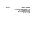

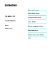
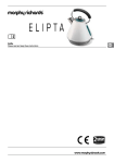

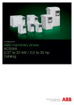


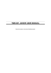
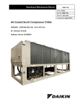

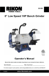
![manual [372769 bytes]](http://vs1.manualzilla.com/store/data/005891066_1-6553408cfa4c941a2bbbbb48a824c132-150x150.png)