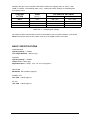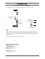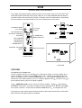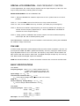
1
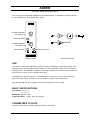
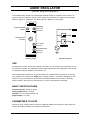
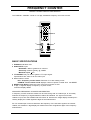
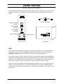
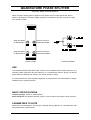
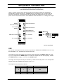
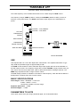
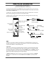
TIMS-801 JUNIOR USER MANUAL
Telecommunications Instructional Modelling System
TIMS-801 JUNIOR USER MANUAL
Issue Number 1.1 October 2001
Published by:
EMONA INSTRUMENTS PTY LTD
a.c.n. 001 728 276
86 Parramatta Road
Camperdown NSW 2050
Sydney AUSTRALIA
COPYRIGHT c 2001 by EMONA INSTRUMENTS PTY LTD
TIMS is a registered trademark of AMBERLEY HOLDINGS PTY LTD
Printed in Australia
CONTENTS
Part I
TIMS INTRODUCTION
TIMS OVERVIEW
SYSTEM CONVENTIONS
Front Panel Sockets
Plug-in Modules
Labeling
Basic Modules List
Basic Specifications
Part II BASIC MODULES USER INSTRUCTIONS
Adder
Audio Oscillator
Buffer Amplifiers
Dual Analog Switch
Frequency and Event Counter
Master Signals
Multiplier
Phase Shifter
Quadrature Phase Splitter
Sequence Generator
Tuneable LPF
Twin Pulse Generator
Utilities Module
Variable DC
Voltage Controlled Oscillator
60kHz Lowpass Filter
1
2
3
4
5
6
7
8
9
11
12
14
15
17
18
20
22
23
25
TIMS INTRODUCTION
TIMS OVERVIEW
TIMS is a telecommunications modelling system. It models mathematical equations representing electrical signals, or block diagrams representing telecommunications systems.
TIMS is primarily a hands-on rather than demonstration style teaching system, which combines
both the theoretical and practical aspects of implementing systems. We are confident that TIMS
will provide the student with a clearer understanding of the concepts behind telecommunications
theory.
Physically, the TIMS-801 JUNIOR is a compact, single rack system. The rack accepts up to 8
Eurocard sized, compatible "telecommunications building blocks", or modules. It also contains 4
fixed modules, as well as the system power supply.
The modules are very simple electronic circuits, which function as basic communications building blocks. Each module, fixed or plug-in, has a specific function; functions fall into four general
categories:
Signal Generation - oscillators, etc
Signal Processing - multipliers, filters, etc
Signal Measurement - frequency counter
Digital Signal Processing - TMS320C50 based
Modules are patched together via the front panel sockets using interconnecting leads, to model
the system under investigation.
TIMS-801 Junior User Manual 1
SYSTEM CONVENTIONS
All TIMS modules conform to the following mechanical and electrical conventions.
A - FRONT PANEL SOCKETS
Signal interconnections are made via front panel, 4mm sockets
Sockets on the LEFT HAND SIDE are for signal INPUTS.
All inputs are high impedance, typically 56k ohms.
Sockets on the RIGHT HAND SIDE are for signal OUTPUTS.
All outputs are low impedance, typically 330 ohms.
YELLOW sockets are only for ANALOG signals.
ANALOG signals are held near the TIMS standard reference level of 4V pk-pk.
RED sockets are only for DIGITAL signals.
DIGITAL signals are TTL level, 0 to 5 V.
GREEN sockets are all common, or system GROUND.
Note that input and output impedances are intentionally mismatched, so that signal connections
may be made or broken without changing signal amplitudes at module outputs.
B - PLUG-IN MODULES
Any plug-in module may be placed in any of the 12 positions of the upper rack. All modules use
the back plane bus to obtain power supply : only the DSP modules (not part of the BASIC SYSTEM) use the bus to transfer signals. The modules are designed so that they may be pluggedin or removed at any time, without turning off the system power. The modules are not locked
into position and may need to be held while interconnecting leads are removed.
C - LABELING
All modules are identified as to the function they perform.
Inputs, outputs, controls and switches are labeled so that a student who has had only a brief introduction to TIMS can use the modules without needlessly referring back to this USER
MANUAL.
It should be noted that no variable controls have calibration marks. This is intentional, as the
philosophy behind TIMS is that students setup and adjust systems by observing and measuring
signals. This assists the student in gaining a much greater understanding, feel and insight into
the operation of a communications implementation.
TIMS-801 Junior User Manual 2
D - BASIC MODULE LIST
Below are listed all the fixed, TIMS-801 JUNIOR SYSTEM MODULES and the optional plug-in
BASIC modules.
TIMS-801 JUNIOR SYSTEM FIXED MODULES
Buffer Amplifiers
Frequency and Event Counter
Master Signals
Variable DC
OPTIONAL BASIC PLUG-IN MODULES
Adder
Audio Oscillator
Dual Analog Switch
Multiplier
Phase Shifter
Quadrature Phase Splitter
Sequence Generator
Tuneable LPF
Twin Pulse Generator
Utilities Module
Voltage Controlled Oscillator
60kHz Lowpass Filter
BASIC SPECIFICATIONS
POWER SUPPLY
Input 110, 127, 220 or 240V AC, 47Hz to 63Hz
Output +15V, 1.25A DC
-15V, 1.25A DC
Protection short circuit, overload, thermal
Regulation 0.2%
PHYSICAL
Case Dimensions 490(W) x 330(D) x 310(H) mm
System Weight 10kg
Plug-in Card Dimensions 160 x 100 mm
Plug-in Card Bus Connectors 64 way, 2 row, Eurocard
MODULES
Specifications for each module are listed in the following pages.
TIMS-801 Junior User Manual 3
ADDER
OPTIONAL BASIC PLUG-IN MODULE
Two analog input signals A(t) and B(t) may be added together, in adjustable proportions G and
g. The resulting sum is presented at the output.
G:GAIN CONTROL
FOR INPUT A
ANALOG INPUT
g:GAIN CONTROL
FOR INPUT B
ANALOG OUTPUT
ANALOG INPUT
FRONT PANEL
BLOCK DIAGRAM
USE
Care must be taken when adjusting the gains to avoid overloading the following modules. Overloading will not cause any damage but it means non-linear operation, which is to be avoided in
analog systems. The ADDER is capable of delivering a signal well in excess of the standard reference level, 4V pk-pk, given a standard level input.
The ADDER can also be used as a normal amplifier by using only one input and turning the
gain of the other input to minimum. It is not necessary to ground the unused input.
Note that gains G and g are negative. All inputs and outputs are DC coupled.
BASIC SPECIFICATIONS
Gain Range 0 < G < 2;
0 < g < 2;
Bandwidth approx. 1MHz
Output DC Offset <10mV, open circuit inputs
PARAMETERS TO NOTE
maximum output level; linearity; polarity inverting; phase shift
TIMS-801 Junior User Manual 4
AUDIO OSCILLATOR
OPTIONAL BASIC PLUG-IN MODULE
The AUDIO OSCILLATOR is a low distortion tuneable frequency sinewave source with a frequency range from 500Hz to 10kHz. Three outputs are provided. Two outputs are sinusoidal,
with their signals in quadrature. The third output is a digital TTL level signal.
INPHASE
ANALOG
OUTPUT
SYNCHRONIZE
INPUT
FREQUENCY
ADJUST
TTL LEVEL
OUTPUT
QUADRATURE
ANALOG
OUTPUT
FRONT PANEL
BLOCK DIAGRAM
USE
The frequency of each of the three outputs is the same and is varied by the front panel ∆ f control. Both the in-phase and quadrature analog output signals have fixed amplitude. Their shape
is sinusoidal, having a distortion of less than 0.1%.
The AUDIO OSCILLATOR may be synchronized to an external periodic signal by connecting
such a signal to the front panel SYNC input. A signal of about 1 volt peak is adequate for this
purpose. For synchronization to be achieved, the AUDIO OSCILLATOR must be manually
tuned to within a few percent of the frequency to which synchronization is desired.
BASIC SPECIFICATIONS
Frequency Range 300Hz to 10kHz
Analog Output Level 4V pk-pk
Distortion <0.1% analog outputs only
Digital Output TTL level
PARAMETERS TO NOTE
frequency range; relative phase of outputs; amplitude stability with frequency range; harmonic
content; short term stability; synchronizing characteristic.
TIMS-801 Junior User Manual 5
BUFFER AMPLIFIERS
TIMS-801 JUNIOR FIXED SYSTEM MODULE
Two independent variable gain amplifiers are provided.
GAIN CONTROL
ANALOG INPUT OF
FIRST AMPLIFIER
ANALOG OUTPUT
GAIN CONTROL
ANALOG INPUT OF
SECOND AMPLIFIER
ANALOG OUTPUT
FRONT PANEL
BLOCK DIAGRAM
USE
These buffers may be used to amplify small signals or attenuate large signals. Each amplifier
has its own gain control on the front panel.
Care should be taken to ensure that later modules are not overloaded due to excessive gain.
Overload will not cause any damage but it means non-linear operation, which is to be avoided
in analog systems. If overload occurs, turn the gain control counter clockwise.
BASIC SPECIFICATIONS
Bandwidth DC to approx. 1MHz
Gain 0 to 10
TIMS-801 Junior User Manual 6
DUAL ANALOG SWITCH
OPTIONAL BASIC PLUG-IN MODULE
Two identical analog switches are controlled by digital, TTL level signals. The outputs of the two
switches are added internally and presented at the output of the module.
ANALOG INPUT 1
TTL CONTROL
FOR INPUT 1
TTL CONTROL
FOR INPUT 2
ANALOG INPUT 2
OUTPUT
FRONT PANEL
BLOCK DIAGRAM
USE
Each switch may be closed independently by a TTL HIGH at the respective control input. The
switch outputs are combined internally and are presented at the common output socket. Open
circuit voltage gain between each input and the module output is unity when the switch is
closed.
BASIC SPECIFICATIONS
Analog Input Bandwidth >300kHz
Maximum CONTROL clock > 100kHz
CONTROL Input Levels TTL only
Maximum Analog Input Level +8V
PARAMETERS TO NOTE
switch On/Off ratio; linearity; switching speed; analog bandwidth; channel cross talk; DC off-set
TIMS-801 Junior User Manual 7
FREQUENCY COUNTER
TIMS-801 JUNIOR FIXED SYSTEM MODULE
The TIMS-801 JUNIOR’s counter is a 5 digit, 99.999kHz frequency and event counter.
1
6
2
5
3
4
BASIC SPECIFICATIONS
1 OVERflow indication LED
2 ANALOG/TTL input:
Bandwidth 40Hz to greater than 100 kHz
Sensitivity 250mV typically, @ 100kHz
Maximum input +12V
3 TTL ENABLE may be used to gate the TTL input signal.
Specifications are same as for the main input.
4 Mode selection switch
kHz : Frequency counter mode Gate time of 1s with reading in kHz
COUNTS : Event counter mode displays number of pulses counted since last RESET
5 RESET Push Button resets the count of the Event Counter to zero
6 5 digit, 7 segment display of frequency or pulse counts;
maximum display 99999
ADVANCED FREQUENCY COUNTER INFORMATION
In frequency counter mode this module can be used, along with an oscilloscope, to accurately
measure the frequency of signals between 100kHz and 900kHz. If a signal of more than
100kHz is input, then the OVERFLOW LED will be lit. However the 5 digit display will always accurately display the 5 least significant digits of the measurement.
So if an oscilloscope is used to determine the frequency of the unknown signal to the nearest
100kHz, this module’s 5 digit display will measure the lower 5 significant digits of the frequency
measurement.
TIMS-801 Junior User Manual 8
MASTER SIGNALS
TIMS-801 JUNIOR FIXED SYSTEM MODULE
Five synchronized analog and digital signals are available, ranging from 2kHz to 100kHz. The
function and frequency of each signal is indicated on the front panel.
QUADRATURE ANALOG
CARRIER SIGNAL
INPHASE ANALOG
CARRIER SIGNAL
TTL LEVEL CARRIER
SIGNAL
TTL LEVEL
ANALOG SIGNAL
FRONT PANEL
BLOCK DIAGRAM
USE
Signals are labeled as follows:
CARRIER signals are 100kHz, which for modelling purposes is sufficiently far from the audio
channel bandwidth of 3kHz.
The SAMPLE CLOCK of 8.3kHz, which may be used to sample bandwidth-limited (3kHz) audio
message signals.
MESSAGE provides an audio frequency signal which is synchronized to a sub-multiple of the
carrier to enable ’text-book’ like displays of simple modulation schemes to be achieved.
The five signals are derived from a master crystal oscillator resulting in low frequency drift.
Their frequencies are fixed internally. The output levels are also fixed. To vary the amplitude,
the signals may be applied to the neighboring buffers.
The analog signals are sinusoidal in shape, having a distortion of less than 0.1%.
Digital signals are all standard TTL level, with rise times of better than 80nsec.
TIMS-801 Junior User Manual 9
BASIC SPECIFICATIONS
Output Frequencies 100kHz, carrier
8.333kHz, sample clock
2.083kHz, audio (carrier sub-multiple)
Output Levels 4V pk-pk, analog
TTL level, digital
Distortion <0.1%, analog outputs only
PARAMETERS TO NOTE
short term frequency stability; relative phase of quadrature outputs; harmonic content.
TIMS-801 Junior User Manual 10
MULTIPLIER
OPTIONAL BASIC PLUG-IN MODULE
Two analog input signals X(t) and Y(t) may be multiplied together. The resulting product is
scaled by a factor of approximately 1/2 so that, with standard level inputs, later stages are not
overloaded.
INPUT COUPLING
SWITCH
ANALOG INPUT
ANALOG OUTPUT
ANALOG INPUT
FRONT PANEL
BLOCK DIAGRAM
USE
The input coupling switch may be used to remove input DC components by switching to AC
coupling. It should be noted that any DC component in the output will not be removed.
The "k" factor (a scaling parameter associated with "four quadrant" multipliers) is approximately
one half. It is defined with respect to the OUTPUT from the module and may be measured experimentally.
BASIC SPECIFICATIONS
Bandwidth approx. 1MHz
Characteristic k.X(t).Y(t)
k approx. 1/2
PARAMETERS TO NOTE
linearity; k factor; carrier leak; phase response; DC off-set; performance as a squarer; frequency response; "conversion gain" as a (de)modulator.
TIMS-801 Junior User Manual 11
PHASE SHIFTER
OPTIONAL BASIC PLUG-IN MODULE
The PHASE SHIFTER introduces a phase shift between its input and output. This phase shift is
adjustable by the user. The frequency range of operation can be selected by PCB mounted
switch.
BLOCK DIAGRAM
COARSE PHASE
ADJUST
FINE PHASE
ADJUST
180O PHASE
CHANGE
ANALOG INPUT
ANALOG OUTPUT
FRONT PANEL
PCB VIEW
USE
This variable PHASE SHIFTER is capable of varying the magnitude of the phase shift through
360 degrees in two steps. The 180 degree switch selects the step or region of interest; the
COARSE and FINE controls are used to then obtain the required phase shift, Φ.
If the input is COS(µt), then the output is COS(µt- Φ), where Φ lies between 0 and 180 degrees.
Although the PHASE SHIFTER will operate from a few hertz up to 1MHz it has been optimized
to operate in the neighborhood of two frequencies: around 100kHz in the HI range and around
2kHz in the LO range. A PCB mounted switch is used to select the frequency range.
The open circuit gain through the PHASE SHIFTER is essentially unity for all phases, but note
that the amount of phase shift, Φ, is a function of frequency. This is NOT a wideband phase
changer: thus all the frequency components of a complex signal’s spectra are not shifted by the
same phase.
TIMS-801 Junior User Manual 12
BASIC SPECIFICATIONS
Bandwidth <1MHz
Frequency Range HI approx. 100kHz *
LO approx. 2kHz *
* For 0 to 360 degree range of phase shift. The phase shift range increases (i.e. resolution
decreases) as the input frequency increases.
Coarse approx. 180 degrees shift
Fine approx. 20 degrees shift
PARAMETERS TO NOTE
Variation of phase change with frequency change.
TIMS-801 Junior User Manual 13
QUADRATURE PHASE SPLITTER
OPTIONAL BASIC PLUG-IN MODULE
When the same analog signal is applied to both inputs, the two output signals will differ in
phase by 90 degrees. The phase splitter networks are wideband, typically covering the range
from 200Hz to 10kHz.
ANALOG INPUT
TO NETWORK 1
ANALOG OUTPUT
FROM NETWORK 1
ANALOG INPUT
TO NETWORK 2
ANALOG OUTPUT
FROM NETWORK 2
FRONT PANEL
BLOCK DIAGRAM
USE
The QUADRATURE PHASE SPLITTER consists of two wideband phase shifting networks. The
networks’ phase responses vary with frequency in a complimentary manner, giving a 90 degree
phase difference between the outputs, over a wide frequency range.
In communications the most important application is the generation and demodulation of Single
Sideband by the "phasing method".
BASIC SPECIFICATIONS
Frequency Range 200Hz to 10kHz typically
Phase Response 90 degrees between outputs, given the same input signal to both networks.
PARAMETERS TO NOTE
Phase error from 90 degrees. This may be measured directly (difficult !) or calculated from sideband suppression measurements.
TIMS-801 Junior User Manual 14
SEQUENCE GENERATOR
OPTIONAL BASIC PLUG-IN MODULE
(PSEUDORANDOM SEQUENCE GENERATOR)
Using a common external clock signal, the sequence generator outputs two independent
pseudorandom sequences X and Y. A SYNC output is provided which is coincident with the
start of the sequences. The sequences may be stopped and restarted at any time via front
panel controls. Sequences X and Y are available as either standard TTL or analog level output.
RESET
PUSH BUTTON
ANALOG OUTPUT
TTL LEVEL
RESET
ANALOG OUTPUT
BEGINNING OF
SEQUENCE SYNC
ANALOG CLOCK
TTL OUTPUT
TTL CLOCK
TTL OUTPUT
FRONT PANEL
BLOCK DIAGRAM
USE
An external clock signal must be provided to operate the SEQUENCE GENERATOR. This may
be sinusoidal or TTL: separate input sockets are used.
The sequences may be stopped at any time by either depressing the RESET button or applying a TTL HI signal to the RESET input. To restart the sequences from the beginning, release
the RESET button or apply a TTL LO to the RESET input.
The length of the sequences may be selected by a PCB mounted dip switch. Four independent
sequence pairs are available from lengths of 25 to 211.
The sequences are selected as follows:
DIP SWITCH CODE
n
SEQUENCE LENGTH 2n
msb 0
0
5
32
0
1
8
256
1
0
8
256
1
1
11
2048
TIMS-801 Junior User Manual 15
BASIC SPECIFICATIONS
Input Clock Range TTL 1Hz to 1MHz
Analog <500Hz to >10kHz
Number of Sequences 4 pairs
Sequence Lengths 25, 28, 28, 211
Sync indicates start of sequence
PARAMETERS TO NOTE
sequence distribution; noise generation using pseudorandom sequences.
TIMS-801 Junior User Manual 16
TUNEABLE LPF
OPTIONAL BASIC PLUG-IN MODULE
The cutoff frequency of this LOWPASS FILTER can be varied using the TUNE control.
Two frequency ranges, WIDE (2.0kHz to 12kHz) and NORMAL (900Hz to 5kHz), can be selected by a front panel switch. The GAIN control allows input signals to be attenuated if required.
CLK/880 = f-3dB; NORMAL
CLK/360 = f-3dB; WIDE
CUT-OFF
FREQUENCY
ADJUST
GAIN ADJUST
FREQUENCY
RANGE SELECT
ANALOG OUTPUT
ANALOG INPUT
FRONT PANEL
BLOCK DIAGRAM
USE
This lowpass filter has a 7th order elliptic filter characteristic. The stopband attenuation is typically 50dB and passband ripple is approximately 0.5dB.
The GAIN control should be used to attenuate large input signals and thus avoid saturation of
the filter output circuits. Two frequency ranges are provided. NORMAL range provides more precise control over the lower audio band, used for telecommunications message channels. The
WIDE range expands the filter’s range to above 10kHz.
The CLK output provides an indication of the filter’s cutoff frequency. Note that above 9kHz the
dividing factor increases from 340 to 430 at 12kHz.
BASIC SPECIFICATIONS
Filter Ranges 900Hz < NORMAL < 5 kHz and
2.0kHz < WIDE < 12 kHz,
continuously variable over each range.
Stopband Attenuation > 50dB
Passband Ripple < 0.5dB
PARAMETERS TO NOTE
corner point; phase shift; gain range; passband ripple; out of band attenuation.
TIMS-801 Junior User Manual 17
TWIN PULSE GENERATOR
OPTIONAL BASIC PLUG-IN MODULE
(TWIN PULSE GENERATOR - VERSION 2.0)
A positive going edge applied at the CLOCK input causes a positive pulse to occur at the output terminals. There are two operating modes: TWIN and SINGLE. Only TWIN mode is limited
to low frequency CLOCK inputs.
In TWIN mode, Q1 outputs the leading pulse and Q2 outputs the delayed pulse. The time between pulses Q1 and Q2 can be varied, as can the pulses’ widths.
In SINGLE mode, only Q1 outputs a positive going pulse, while Q2 outputs the inverse of Q1.
The pulse width can be varied.
ERROR LED, INDICATES
IF 2tW + tD > tCLK
BLOCK DIAGRAM
PULSE WIDTH
CONTROL
DELAYED PULSE
OUTPUT:
TTL LEVEL
LEADING PULSE
OUTPUT:
AC COUPLED
DELAY TIME
CONTROL
DIGITAL CLOCK
TTL LEVEL OUT
FRONT PANEL
TIMING DIAGRAM
USE
A digital TTL level signal is applied to the CLK input. The GENERATOR then outputs one or
two pulses, depending upon the operating mode selected. Use the PCB mounted MODE switch
to select either SINGLE or TWIN operating mode.
TWIN MODE
TWIN mode is used when two sequential pulses are needed. Two equal width positive pulses
occur as a result of each CLK signal positive edge. Pulse Q1 always occurs before pulse Q2.
The width of both pulses is controlled by the front panel WIDTH control. The DELAY control varies the spacing between the two pulses. Note that TWIN mode will only accept CLOCK input
signals of up to 50kHz, depending upon front panel settings.
If WIDTH and DELAY have been incorrectly set, causing anomalous operation, the ERROR
LED will be lit. To eliminate the error reduce DELAY and then WIDTH - by turning counter
clockwise.
TIMS-801 Junior User Manual 18
SINGLE MODE
SINGLE mode is used to obtain a train of equal width pulses from any TTL level signal.
Equal width positive pulses occur at Q1 output as a result of each CLK signal positive edge.
The width of the pulses is controlled by the front panel WIDTH control. Q2 simultaneously outputs the compliment of Q1. The DELAY control is not used in this mode.
Note that Q1 includes both a TTL level and an AC coupled output pulse.
BASIC SPECIFICATIONS
TWIN MODE
Clock Frequency Range < 50kHz
Pulse WIDTH 3µs < tw < 25µs
Pulse DELAY Q2-Q1 10µs < td < 120µs
Error Indication 2tw + td > tCLK
SINGLE MODE
Clock Frequency Range < 200kHz
Pulse WIDTH 3µs < tw < 25µs
TIMS-801 Junior User Manual 19
UTILITIES MODULE
OPTIONAL BASIC PLUG-IN MODULE
The Utilities Module houses 4 independent functional blocks:
(i) A signal COMPARATOR with TTL output and CLIPPER with bipolar output, for squaring analog waveforms. The COMPARATOR’s threshold level may be set as required by applying a DC
voltage to the REF input. The CLIPPER’s gain may be set by adjusting DIP switches SW1 and
SW2.
(ii) Precision halfwave RECTIFIER.
(iii) Simple diode and single pole, audio range, RC Lowpass Filter.
(iv) Single pole, audio range, RC Lowpass Filter.
CLIPPER
BIPOLAR OUTPUT
ANALOG REFERENCE
INPUT
ANALOG SIGNAL
INPUT
COMPARATOR
TTL OUTPUT
ANALOG INPUT
ANALOG OUTPUT
ANALOG INPUT
ANALOG OUTPUT
ANALOG INPUT
ANALOG OUTPUT
FRONT PANEL
BLOCK DIAGRAM
USE
COMPARATOR
The COMPARATOR will square any analog signal and provide a standard TTL level output.
The switching threshold level is determined by the voltage level applied to the REF input.
NOTE: For correct COMPARATOR operation, the REF input must never be left unconnected.
The REF input may be connected to GROUND, VARIABLE DC or any other signal source.
CLIPPER
The CLIPPER will amplify any analog TIMS level signal and then clip the amplitude of the amplified signal, to a fixed level of approximately +1.8V. The clipping action is performed by standard
small signal diodes.
NOTE: The REF input is NOT used by the CLIPPER.
TIMS-801 Junior User Manual 20
Adjusting the gain of the CLIPPER, determines whether the clipping action is "SOFT", "MEDIUM" or "HARD". The following table, UTIL-1, relates DIP switch settings to CLIPPER gains
and clipping action,
CLIPPING
ACTION
GAIN
DIP SWITCH SETTINGS
(approx.)
SW1 (both a & b)
SW2 (both a & b)
SOFT
x0.8
ON - ON
OFF - OFF
MEDIUM
x8
OFF - OFF
OFF - OFF
HARD
x40
OFF - OFF
ON - ON
-
not applicable
ON - ON
ON - ON
Table UTIL-1: CLIPPER gain settings
DIP switches SW1 and SW2 will be found in the middle of the UTILITIES module’s circuit board.
NOTE: Both halves (bits) of each switch must be in the SAME position at all times.
BASIC SPECIFICATIONS
COMPARATOR
Operating Range > 500kHz
TTL Output Risetime 100nsec (typ)
CLIPPER
Operating Range > 500kHz
Output Level 1.8Vpk (typ)
Adjustable Gains 3 steps; x0.8, x8 and x40 (approx.)
RECTIFIER
Bandwidth DC to 500kHz (approx.)
DIODE & LPF
LPF -3dB 2.8kHz (approx.)
RC LPF
LPF -3dB 2.8kHz (approx.)
TIMS-801 Junior User Manual 21
VARIABLE DC
TIMS-801 JUNIOR FIXED SYSTEM MODULE
The VARIABLE DC module is a stable, bipolar DC source and a fixed +5V output.
+5V
DC VOLTAGE
CONTROL
DC OUTPUT
GROUND
REFERENCE
FRONT PANEL
BLOCK DIAGRAM
USE
The DC voltage output varies from about -2.5V when the control is fully counter clockwise
through zero to +2.5V when control is turned fully clockwise. If greater resolution or wider range
is required, then one of the BUFFER AMPLIFIERS can be used in conjunction with the VARIABLE DC module.
The fixed output provides a TTL level logical HI, +5V.
BASIC SPECIFICATIONS
Voltage Range +2.5V DC
Short-term Stability < 2mV/hr
Resolution approx. 20mV
Output Current < 5mA
Fixed Output +5V DC
Output Current approx. 15mA
TIMS-801 Junior User Manual 22
VCO
OPTIONAL BASIC PLUG-IN MODULE
The Voltage Controlled Oscillator module functions in two modes: either as a VOLTAGE CONTROLLED OSCILLATOR with analog input voltage or as an FSK GENERATOR with digital input. Both modes have two frequency ranges of operation which are selected by a range switch.
The VCO frequency and input sensitivity can be controlled from the front panel.
FSK DATA INPUT
- TTL LEVEL
TTL LEVEL
OUTPUT
SET SENSITIVITY
OF INPUT CONTROL
VOLTAGE
Vin OVERLOAD
INDICATION LED
SET CENTER
FREQUENCY
BLOCK DIAGRAM
FREQUENCY
RANGE SELECCONTROL VOLTAGE
INPUT
ANALOG OUTPUT
FRONT PANEL
PCB VIEW
VCO USE
STANDARD VCO OPERATION
The VCO output frequency is controlled by an analog input voltage. The input voltage, Vin, is
scaled - amplified - by the front panel GAIN control. A DC voltage can be added to Vin internally, thus setting the start or CENTER FREQUENCY, fo . The CENTER FREQUENCY is defined as the VCO output frequency, when no voltage is applied to the Vin connector. The Vin input is internally tied to ground if no signal is applied.
The Vin OVERLOAD LED is lit when the sum of these voltages - scaled Vin plus CENTER
FREQUENCY DC offset - exceed the oscillator’s internal operating limits. Decrease the GAIN turn counter clockwise - and/or shift the CENTER FREQUENCY, fo , to extinguish the LED.
The frequency range switch selects between the HI or carrier band and the LO or audio band.
Both sinewave and digital outputs are available.
TIMS-801 Junior User Manual 23
SPECIAL VCO OPERATION - FINE FREQUENCY CONTROL
In some applications, fine control may be required over the output frequency of the VCO. This
may be easily achieved by following these four steps:
MODULES REQUIRED: VCO and VARIABLE DC.
STEP 1 - Set the VARIABLE DC module’s output close to zero (marker knob at 12 o’clock
position).
STEP 2.1 - Turn the GAIN control of the VCO to zero, fully counter-clockwise.
STEP 2.2 - Now, turn the GAIN control up, clockwise, just a little (only a few degrees).
STEP 3 - Set the VCO module’s output frequency as close as possible to the frequency of
interest. Use the frequency adjust knob, fo. Use the FREQUENCY COUNTER to
measure the VCO’s output frequency.
STEP 4 - Finally, patch the VARIABLE DC module’s output to the VCO module’s frequency
control input, Vin, with a standard patching lead.
FINE FREQUENCY CONTROL of the VCO module is now achieved by turning the VARIABLE
DC module’s voltage control knob.
FSK USE
A PCB mounted slide switch selects between FSK and VCO modes of operation. The two output frequencies, FSK1 and FSK2 , (MARK and SPACE), are set by varying the PCB mounted,
finger adjustable trimmers. As in VCO mode, the frequency range switch selects between the
HI or carrier band and the LO or audio band. The digital data input accepts only TTL level signals. Both sinewave and digital outputs are available.
GAIN and CENTER FREQ, fo , controls and the Vin connector are not used in the FSK mode.
BASIC SPECIFICATIONS
VCO MODE
Frequency Ranges 1.5kHz < LO < 17kHz; sinewave and TTL
( <300Hz with external input voltage, Vin )
70kHz < HI < 130kHz; sinewave and TTL
Input Voltage -3V < Vin < 3V
Overload limit indication LED Vvco > + 3V;
Vvco is the internal voltage finally applied to the VCO circuitry.
GAIN G.Vin : 1 < G < 2
Center Frequency Voltage Range - 3V < Vfc < 3V;
Vfc is a DC voltage added INTERNALLY to G.Vin
FSK MODE
Frequency Ranges 1.5kHz < FSK1, LO < 9kHz
500Hz < FSK2, LO < 4kHz
80kHz < FSK1, HI < 200kHz
20kHz < FSK2, HI < 120kHz
Data Input TTL level message
TIMS-801 Junior User Manual 24
60kHz LOWPASS FILTER
OPTIONAL BASIC PLUG-IN MODULE
An elliptic lowpass filter is provided with a cutoff point of approximately 60kHz. The input signal
amplitude can be adjusted with the gain control.
INPUT GAIN
CONTROL
ANALOG OUTPUT
ANALOG INPUT
FRONT PANEL
BLOCK DIAGRAM
USE
The 60kHz LPF allows carrier signals to be removed from a given signal spectrum.
For example, as the lowpass filter for envelope detector applications.
The GAIN control allows input signals to be attenuated, to avoid overloading the filter.
BASIC SPECIFICATIONS
Cutoff Frequency approx. 60kHz
Passband Gain variable, 0 to 5 (approx.)
Stopband Attenuation 50dB (typ)
Passband Ripple 0.1dB (typ)
PARAMETERS TO NOTE
corner point; response shape; passband ripple; phase shift; out of band attenuation.
TIMS-801 Junior User Manual 25