1
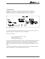
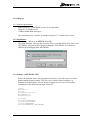
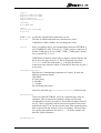
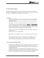
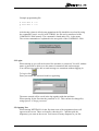
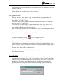
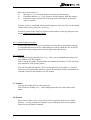
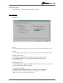
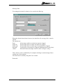
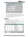
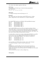
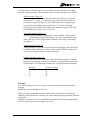
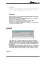
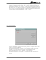
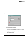
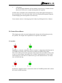
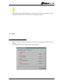
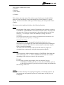
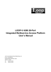
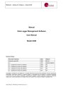
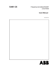
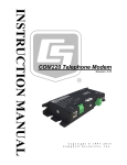
Table of Contents
1.0 INTRODUCTION. .............................................................................................................................. 3
1.1 SETTING UP:........................................................................................................................................... 4
1.1.1 System requirements:..................................................................................................................... 4
1.1.3 Settings: (NETTROLL.INI)............................................................................................................. 4
2.0 FUNCTIONAL DESCRIPTION......................................................................................................... 7
2.1 START-UP: ............................................................................................................................................. 7
2.2 PROGRAMMING COMTROLL 5000. ....................................................................................................... 7
2.3 LOGIN: .................................................................................................................................................. 8
2.5 OPENING NET: ....................................................................................................................................... 8
2.6 LOGGING OF EVENTS: ............................................................................................................................. 9
2.6.1. Log search:................................................................................................................................... 9
2.6.2. Acknowledging messages :...........................................................................................................10
2.6.3. Print-out:.....................................................................................................................................10
2.7 TOOLBARS: ...........................................................................................................................................10
2.8 WINDOW: .............................................................................................................................................10
2.9 SPECIAL SET-UPS: ..................................................................................................................................11
2.9.1 Set criteria: ..................................................................................................................................11
2.9.2. Message texts: .............................................................................................................................13
2.9.5. Terminal:.....................................................................................................................................16
2.10 GROUP:...............................................................................................................................................16
2.10.1. Group operation:.......................................................................................................................17
2.10.2. Group polling:...........................................................................................................................18
3.0 CONTROL/SURVEILLANCE..........................................................................................................19
3.1 SYMBOLS:.............................................................................................................................................19
3.2 CONTROL: ............................................................................................................................................20
3.2.1 Remotely controlled switches:.......................................................................................................20
3.2.2. Repeaters: ...................................................................................................................................23
3.2.3. Indicators:...................................................................................................................................23
3.2.4. Manual switches:.........................................................................................................................23
3.3 TOOLBAR BUTTONS: ..............................................................................................................................24
3.3 STATUS-BAR: ........................................................................................................................................25
NetTroll 2.1 UserGuide
Side 2 av 26
1.0 Introduction.
NETTROLL for Windows-95 is a remote control and surveillance program for
NORTROLL outstations, e.g. COMTROLL-200AR switchgear. A Modem with
NETTROLL connects to the sentralunit COMTROLL 5000 via the gateway.
Fig 1, System overview.
The outstations that shall be controlled/monitored are represented as intuitive symbols in a
single line diagrams or a diagram with a map as a background.
Three types of symbols:
-
Remote Controlled switchgear / repeater
Remote fault indicator
Manually operated switchgear
These symbols indicates the position of the remote controlles and manually operated switch,
and if there are active alarms in the system. Any event in the system are automatically
logged in a text file that can be written out. Each node in the network has its own texteditor, where information about last service, road descriptions, phone numbers etc. can be
stored.
NETTROLL can be installed on a portabel PC for home duty. Its communicating with the
stationary NETTROLL via an ordinary phonemodem or GSM.
NetTroll 2.1 UserGuide
Side 3 av 26
1.1 Setting up:
1.1.1 System requirements:
486/Pentium PC. 16MB RAM or more is recommended.
Windows 95/ Windows NT
15MB available hard-disk space.
We recommend a 20” monitor. In smaller network a 17” monitor can be used.
1.1.2 Installation:
Choose run... and write A: SETUP. Push OK.
The Setup Program will copy the necessary files to your hard-disk, and create a new
NETTROLL program group in Program Manager. NETTROLL-95 contains in
addition the drawingprogram NETDRAW.
1.1.3 Settings: (NETTROLL.INI)
Before the program startes some parameters must be set in a file nettroll.ini that is
underneath the nettroll-catalog. This file can be edited with an texteditor e.g.
Windows NotePad. Below you can find an example on a nettroll.ini-file and an
explenation on the different sentences in this file:
[Comm]
Wait=200
Port1=1
Settings1=1200,N,8,1
WaitStatus=20
WaitMessage=20
[Station]
Station1=SWITCHGEAR
Station2=INDICATOR
Station3=REPEATER
Station4=MANUALLY SWITCHGEAR
NetTroll 2.1 UserGuide
Side 4 av 26
[Type]
Type1=1,ComTroll-200AR
Type2=1,Comtroll-200BR
Type3=3,Repeater
Type4=2,Fault-indicator
[Netfile]
File=DEMO.NET
[Misc]
Serial=1234-234-542AZ
Logout=30
In the [Comm] section the communication parameters are set:
Wait=200
The time in milliseconds between each character sent to
COMTROLL 5000 is 200ms. Do not change this value.
Port1=1
Port1 is a software driver for communication between NETTROLL
and COMTROLL 5000. If its set to 1, COM3 must be connetced. If
another COM-port is in use (COM2, COM3, COM4) port1 must be
set to respectively 2, 3 or 4.
If NETTROLL shall be connected to a superior sentral-solution, the
driver for a new gate must be set. This is being done by writing
Port2=x on the line underneath.X is the gate that shall be
connected to the surperior sentral. X must not be the same for port 1
as for port2.
Settings1=1200,N,8,1
Discribes the Communication parameters for port1. In order the
different parameters means:
1200 Baud
N: None parity.
8: 8 databit
1: 1 stopbit.
Do not change this values.
If port2 is activated, type Settings2=1200,N,8,1 in the next line.
WaitStatus=20
Time in seconds NETTROLL waits for a statusmessage from an
outstation, after an status interrogating is being sent. In some
configurations it can be necessary to extend the time higher than 20
sec(e.g. 30sec), especially with several serial repeaters between the
station and sentral. You can decrease the time if the outstations have
direct contact with the sentral, or only via repeaters. The total time
for a group interrogation or the time a........ of all the stations will
decrease. polled outstation
WaitMessage=20
NetTroll 2.1 UserGuide
Side 5 av 26
In principle the same as for WaitStatus but set the time in seconds
between a command message and an updated status message.
In the [Station] section the four predefined stationtypes that can be programmed
by NETTROLL are listed. These predefined stationtypes will have different
stationmenyes in NETTROLL, adjusted to the function this station execute. They
will also have their own symbol in the diagram. E.g. if one of the types does not
exist in your remote control system, it can be deleted.
In the [Type]section you can define your own stationtypes. You can define upto 10
different kinds. Each stationtype has its own set of message texts for the different
messages.These you can change in a database. (See chapt. 2.9.2 Registration of
message texts). You can also make your own stationtype for spesific configurations.
However you must set up which of the four maintypes the station goes underneath.
Example 1:
Type1=1,ComTroll-200AR
Type1=1
ComTroll-200AR
Type1 is a Remote controlled switch. (Station1 = switch).
The name for Type1 station. (Can be choosen)
(The number behind the sign of equality says which of the four maintypes Type1 is)
In the [Netfile] section the filename of the diagram you drawed in the one-singlediagram
is written.
Example :
File=DEMO.NET
I the section [Misc] the sentences means:
Serial=xxxxxxx
Serialnumber to the program..
Logout=30
Time dependant logout. The time is given in seconds from the last
operation till the program is locked. After this time has expired
username and password must be entered in order to operate the
outstations.
NetTroll 2.1 UserGuide
Side 6 av 26
2.0 Functional description.
After the installation you will find a specific Nettroll program in the folder containing
NETTROLL and NETDRAW (the single line diagram editor). Before starting NETTROLL
you must start NETDRAW to build the desired screen image(s).
2.1 Start-up:
Starting up NETTROLL can be done after all outstations have been programmed.
This is done in NETDRAW. (See own documentation for the single line diagram
editor NETDRAW).
NETTROLL is started by opening the Nettroll-folder. Click the NETTROLL-icon.
NETTROLL stores status of outstations defined as switches and manual switches
when terminating the program. When starting the program again you will therefore
get the previously stored status of the outstations that is not necessarily correct. In
order to verify that the image you get when starting NETTROLL is the correct one
you should always start by interrogating status of all outstations.
To get the best possible use of NETTROLL the program should run continuously
around the clock
Therefore: Never shut down NETTROLL.
NETTROLL will start logging of events even if message boxes appear during startup.
After starting NETTROLL the network drawings made in NETDRAW must be
opened. This is done by choosing Net…, followed by the various networks.
Use the Maximise-button in the top right corner to get a full-screen image.
2.2 Programming COMTROLL 5000.
Programming the COMTROLL 5000 can be done in various ways. You may build in
the switches using the keyboard unit of the COMTROLL 5000 or by using the
terminal programme under Windows. This approach is explained in the user guide of
the COMTROLL 5000.
COMTROLL 5000 may also be programmed from NETTROLL. This is done
mainly in the same way as when using a terminal programme, but instead of sending
line by line to the COMTROLL 5000 you have to create a file where all outstations
are built in. The simplest way to do this is by using notepad under Windows.
NetTroll 2.1 UserGuide
Side 7 av 26
Example programming file:
B 4545 4545 A 77 A
B 4555 4555 C 77 A
:
:
After having written in all relevant outstations the file should be saved and by using
the command Transfer textfile in NETTROLL the file can be transferred to the
COMTROLL 5000 memory. The command is found under File.. in the menu.
The various commands are explained in the user guide of the COMTROLL 5000.
2.3 Login:
When starting up you will not be asked for username or password. You will, without
name or password be able to see the status of outstations and read messages.
You will however not be able to send messages to outstations without logging in.
.
To log in click
Enter your name and password in th box appearing:
The name entered will be saved in the log together with date and time.
When starting for the first time the password is 123. This can later be changed by
using Options../Change password.
2.5 Opening Net:
When starting NETTROLL for the first time none of the programmed nets will
appear on the screen. These are found by choosing Net... and then pick the
diagram(s) you want on the screen. You can run as many diagrams as you like
NetTroll 2.1 UserGuide
Side 8 av 26
simultaneously on the screen and you can switch between the diagrams by using the
buttons in the net.
Place the nets in a way that gives the best overview.
2.6 Logging of events:
During start-up of NETTROLL a log will automatically be opened where all
messages and events will be saved. Everything is saved to a file that will be named in
the pattern: YYYYWW.LOG.
If starting NETTROLL for the first time on a Monday in week 25, the filename of
the log appears as 199625.LOG.
If closing NETTROLL, to open it again later the same week NETTROLL will
automatically open file 199625.LOG and continue filling this log. This ensures that
you will have all messages previously saved.
By the end of each week the log will automatically close and a new log-file under a
new name will be opened.
You can access the “old” log by opening the file from a text-editor.
You open the log by clicking
, or by choosing View../Log.
You return to the diagram by clicking the same button again.
The log is divided in two sections: Mainlog and Filterlog.
The Mainlog stores all incoming and outgoing messages, while the Filterlog only
stores “filtered” messages. This filter can be set for predetermined message types or
predetermined outstations.
How to define filters will be explained later.
Changing between Mailog and Filterlog is done by clicking on the desired sheet in
the bottom left corner
2.6.1. Log search:
As the main log and/or the filter log will increase in time, it will be increasingly timeconsuming to go back to look at “old” messages. If you want to look for messages
from a specific out-station or a specific type of message, the “search” function is a
helpful tool. In order to access this function the desired log must be the active
window on the screen. You activate it by double-clicking anywhere on the log.
The following image will appear:
NetTroll 2.1 UserGuide
Side 9 av 26
Enter the search criteria i.e.:
a)
Message (i.e. 03). Searches all lines in the log for this message.
b)
Outstation address (i.e. 1234). Searches for all messages from this address.
c)
Outstation name. Searches for all messages from this station. In principle
same as under b).
After the search is completed, the result will appear in a new log. This can be printed
out the usual way by using File../Print log..
In order to return to the main log, double-click anywhere on the log and start a new
search without entering search criteria.
2.6.2. Acknowledging messages :
All messages entered in the log are printed in red. In order to signal that a message
is read and understood it can be acknowledged as follows: Mark the line of the log
that shall be acknowledged, then click the right mouse-button once.
2.6.3. Print-out:
You print the log by choosing File../Log... Here you set standard print setups as in
any Windows-95/-NT program.
How to set up the printer is found in the user manual for Winows-95/-NT and in the
user manual for your specific printer.
You can also print old log files. These can be opened in a text editor i.e. Notepad.
From here you can print the whole or parts of the document. Further information on
Notepad is found in the Windows-95/-NT manual.
2.7 Toolbars:
You can show/hide the tool- and status bars.
This is done by clicking View…, then ticking the menus you want on the screen
image.
2.8 Window:
The various windows (net or log) can be placed anywhere on the screen. Under
Window... you can arrange the windows as you want them. The various options
follow the usual Window-standard.
NetTroll 2.1 UserGuide
Side 10 av 26
2.9 Special set-ups:
Under Options.. you can set various function criteria.
2.9.1 Set criteria:
Parameters:
Port 1:
Connecting/disconnecting port 1 (Port 1 must be defined in NETTROLL.INI).
Port 2:
Connecting/disconnecting Port 2 (Port 2 must be defined in NETTROLL.INI).
Double status-check:
The programme will send the interrogation message twice if no reply
is received the first time. This is especially important in areas with
weak radio signals.
Log messages to file:
For switching on/off logging to file. NETTROLL will start saving to a file at next
start-up independently from this setting.
Time dependant polling
Activated if an interrogation message is wanted for all out-stations at
a certain hour every 24 hrs. The time of interrogation is set in the
check box Set Time in format: Time:Minute.
NetTroll 2.1 UserGuide
Side 11 av 26
Message filter:
For setting the criteria for what is to be saved in the filter log.
When the desired criteria have been set, the check box Set message filter must be
clicked.
The options are:
Date:
All messages within a certain time-span are logged.
Node No:
All messages from a certain out-station are logged.
Node type:
All messages from a certain type of out-stations are logged.
Message:
Certain types of messages are logged. (Maximum three at the time).
Alarm:
When the chosen messages come in, the PC will give a beep.
These choices can be combined by for example selecting a certain message from a
certain type of out-stations.
The filter can be erased by using the Clear button.
Password:
NetTroll 2.1 UserGuide
Side 12 av 26
You can create your own password. Enter your old and new password.
You will not see the password you are entering. Each character will be shown as‘*’.
In order to verify the new password it must be repeated in the box “Repeat new
password”. If one of the entries is misspelled the new password will not be entered.
Click Set to activate the new password.
Next time when logging in you must use the new password.
2.9.2. Message texts:
In order to write your own message texts on the self-defined types of outstations
choose: Options…/Messages…, then enter the password:
NOTE! NetTroll 2.1.1 or older have no password. Press <enter>.
You will now enter a database where all message texts are saved. This database can
be edited in NETTROLL or by use of the database programme Access ver 2.0. The
database will be saved in the file NODE.MDB.
NetTroll 2.1 UserGuide
Side 13 av 26
The columns in the database signify the following:
Node Type:
For entering the self-defined types of stations already programmed in
NETTROLL.INI.
For Type1 set 1, for Type2 set 2 etc.
Message no.
For setting the message concerned. (Message 0 to 15).
KontraNr:
This column applies only when using extended DTMF-protocol. (6 digits).
Where 5 digit protocol is used, the Kontra.nr is set equal to Message no.
In a 6-digit DTMF-protocol you will find the following additional messages:
Msg. 20:
Kontramelding for Msg. 4.
Msg. 21:
Kontramelding for Msg. 5.
Msg. 24:
Kontramelding for Msg. 8.
Msg. 25:
Kontramelding for Msg. 9.
Msg. 28:
Kontramelding for Msg. 12.
In an extended DTMF-protocol you will have a dynamic up-dating of alarms.
If for instance Msg. 9 is sent from an out-station (Msg. 9 input active low), Msg. 25
will be sent from the out-station when this input goes high again. This means that
the error message disappears and the system goes back to normal. NETTROLL will
then remove/reset any alarms from this specific out-station.
In certain software versions in out-stations (starting from 600COM3), it is possible
to activate the 4 extra relay outputs existing in the RTU-200 (6-digits only).
This can only be done from NETTROLL. These additional commands are:
Msg 30:
Activates Relay 5 for 1 sec.
Msg 31:
Activates Relay 6 for 1 sec.
Msg 32:
Activates Relay 7 for 1 sec.
Msg 33:
Activates Relay 8 for 1 sec.
Any text-string may be added to these messages, same as other messages.
To send these messages, see under Terminal communication.
NOTE!
You should not set kontramelding on inputs with connected equipment (i.e.
RABBIT fault indicator) which only gives a short pull of the relay in a fault
situation. This will only activate the alarm indicator in NETTROLL for one second
until the relay drops.
In this case the fault can only be seen by reading the log.
MessageType:
NetTroll 2.1 UserGuide
Side 14 av 26
You may choose what messages are to be defined as status message, activating
message or alarm message. The definitions of the various messages are as follows:
Status message (Type=8):
Status messages are set on out-stations defined as switches or repeaters.
(Message no.. 1, 2 and 3). A status message can at the same time be an
activating or alarm message.(e.g. if a switch represents a normally open
point, an alarm is wanted if the switch closes). The value of a status
message (8) is then added to the value of an alarm message (4). The field
under MeldType is then set to 12 (8+4=12)
Activating message (Type=1):
Messages that are meant for trigging the “circle indicator” in the symbol
representing switches and repeaters, are set as activating messages.
This is also the case for single remote indicators. The value of activating
messages is 1.
Alarm messages (Type=4):
Alarm messages are placed in a specific alarm list trigging a red traffic light
in addition to the changing of colours of the symbol. Alarm messages can
also be activating messages or counter messages.
Counter messages (Type=2):
Counter messages acknowledge activating and alarm messages. It must be
stated which activating or alarm message that is being acknowledged in the
field Komp.Nr. The following messages are set up with counter messages:
Message:
4
5
8
9
Counter message:
20
21
24
25
Example:
You want message no. 2 from a remote switch to be both a status and an alarm
message
MeldType is set accordingly to 8+4=12.
In the case of an earthfault and short-circuit sensor connected to an out-station
(MSG4) which is defined as a switch, you want an alarm message when the indicator
is activated:
MeldType is then set to 4. If a complimentary message is desired (meaning that the
sensor is reset), the counter message is set to 20.
NetTroll 2.1 UserGuide
Side 15 av 26
MessageText:
This is for writing your own text. The text should however be consistent with the
messages being sent from NORTROLL’s out-stations. A description of these
messages are found in the COMTROLL 5000 user guide.
IMPORTANT:
Make sure that there are no other types of stations defined in the file NODE.MDB
than those listed in NETTROLL.INI
Indicators can not be set up with status messages, but message no. 1, 2 and 3 may
well be used as activating or alarm messages.
0 can not be set as a value in the field StType in the file NODE.MDB
NODE.MDB may only contain messages actually occurring.
If a message not listed in NODE.MDB should occur, the text unregistered message
will appear together with the message
2.9.5. Terminal:
In NETTROLL there is a terminal emulator where you can send commands to
COMTROLL 5000 in the same way as in the terminalprogramme in Windows. This
is particularly useful in service contexts or when you have out-stations with special
soft-ware versions. You may also programme out-stations in COMTROLL 5000
from this menu.
The additional commands Msg30, Msg31, Msg32 og Msg33, can be sent from this
menu, but only after the status interrogation of the out-station has been completed.
For an in-depth description of ASCII-commands, see the user guide for this unit.
2.10 Group:
NetTroll 2.1 UserGuide
Side 16 av 26
A group of out-stations can be selected. This is done by clicking the different outstations while holding the Shift-key down. Be sure not to click the name-button, but
the symbol itself. You can put out-stations from different nets together in one group.
There are two different group commands: Group interrogation and Group operation.
You will find the group commands under: Group…/Control..
2.10.1. Group operation:
You can command the switches to the opposite position in a sequence. This is done
in the Group Command Window.
NETTROLL will during the execution of group operation read the status of the
switches. It is therefore not necessary to give the command IN or OUT.
Each command sequence must be confirmed for each outstation.
NETTROLL will execute the sequence in the same order as the out-stations are
chosen.
NetTroll 2.1 UserGuide
Side 17 av 26
2.10.2. Group polling:
If more information is wanted automatically in the interrogation sequence, this can
be done in three ways by using Group polling:
1.
Interrogate all outstations in net.
NETTROLL will send an interrogation to all stations in the net chosen from
the menu above.
2.
Group.
You can interrogate all stations chosen as a group. See the above chapter
about how to select a group.
NetTroll 2.1 UserGuide
Side 18 av 26
3.
All stations.
By choosing this alternative all out-stations, irrespectively of which network
they are in, will receive a status interrogation in a sequence.
In all the above alternatives the outstation that is being interrogated will appear in
the out-station box. You can at any time cancel an on-going interrogation sequence.
Acknowledging each interrogation is not necessary.
If you want to remove a chosen group, this is done by clicking the Cancel-button.
3.0 Control/Surveillance.
This chapter gives the necessary background to interpret the information given by
the symbols. The chapter also explains how to operate an out-station.
3.1 Symbols:
2)
1)
Symbol for a remotely controlled switch or repeater. 1) shows the switch/repeater in
CLOSED/ON position, and 2) the same out-station in OPEN/OFF position.
The circle in the top left corner gives the sensor-input of the out-station. If the circle
is grey, no sensor-input is activated. If it is yellow it means that one or more of the
sensor-inputs are activated. You then have to go to the station menu to see which
one, or look in the log.
1)
2)
Symbol for a manual switch. 1) shows the switch in CLOSED position and 2) shows
the switch in OPEN position.
NetTroll 2.1 UserGuide
Side 19 av 26
The symbol representing an indicator. If the colour is yellow an activating or alarm
message has been received. If it is grey no message has come in.
3.2 Control:
3.2.1 Remotely controlled switches:
When a switch is being interrogated or operated, you click the name-button of the
switch.
The station menu of the actual switch will then appear.
NetTroll 2.1 UserGuide
Side 20 av 26
This window contains three fields:
a) Control
b) Alarms
c) Text Editor.
a) Control.
This window gives the name of the station, type of station (previously defined),
status of switch and finally if any alarm inputs have been activated (i.e. sensorinputs). In order to determine what type of alarm input, you must open the Alarmwindow.
The buttons on the right hand side have the following functions:
Status:
Interrogation of the switch’ position. Depending on the software version in
COMTROLL-200AR/BR the activated sensor inputs will be interrogated at
the same time. If there are out-stations in the system who do not have this
software, a “13-message” can be sent manually by using Alternativecommand.
(Out-stations with soft-ware versions starting from 600UNI04 will automatically read
sensor-inputs when interrogated by a “11-message ”).
Opening and closing:
An out-station can only be opened if already closed and vice versa.
NETTROLL will automatically send status interrogation before sending an
open/close command. Therefore it is not necessary to send status inquiry
before executing commands.
The status line at the bottom of the screen will show the progress of
communication continuously during the interrogation sequence.
Advanced:
You can send any of the messages existing in COMTROLL 5000 from this
menu. (Messages 6, 10, 11, and 13). Additional commands are available
depending on the software-version in the out-stations.
Example:
If you wish to read the sensor inputs of an out-station of the type
COMTROLL-200BR with older software than 600UNI04, write 13
in the field Command. If you wish to see the message text defined for
this message, click View
Cancel:
This choice interrupts an ongoing interrogation or command sequence. By
interrupting an interrogation sequence the switch status will be given as
Undefined.
NetTroll 2.1 UserGuide
Side 21 av 26
b) Alarms:
This window will give a listing of alarms (if any) that have come in. Only messages
that have been listed in the message text data-base will be given. If no alarm has
been set, the text-string belonging to the counter-message will be listed. A grey box
before the text-string indicates that no alarm has come in. A yellow box indicates an
alarm message.
Texteditor:
For each out-station there is a texteditor where information relevant for this
specific station can be stored (last maintenance, access description, etc.)
NetTroll 2.1 UserGuide
Side 22 av 26
When opening this window the text-box will be blank. In order to see what has been
entered earlier click Open. After having written the new text, click Save. This will
enable you to access the information later.
Important!
If you do not click Open before entering new text, the new text will replace the old
one, thus loosing what is previously saved.
3.2.2. Repeaters:
There is in principle no difference between the menu of a repeater and that of a
switch. The repeater is switched ON/OFF same as operating a remotely controlled
switch. Alarms are handled the same way as for switches. The repeater also has a
text box.
3.2.3. Indicators:
Indicators using the DTMF protocol have no possibility of handling commands from
NETTROLL. The station menu found on indicators will therefor not have the
command buttons found on remotely controlled switches and repeaters. All
indicators have their own texteditor.
3.2.4. Manual switches:
Manual switches can not be remotely operated. Setting of status of a manual swich
is done manually in the station window:
Mark the position of the switch by using one of the options in the status box. Click:
Set. The station window will close automatically.
NetTroll 2.1 UserGuide
Side 23 av 26
3.3 Toolbar buttons:
Log-in:
By clicking this button the out-stations will be locked to prevent operation of the
out-stations. In-coming messages will still be saved in the log, and any possible
change of status will be understood.
This button overrides the time-set automatic log-out..
Switching off/on communication gate no. 1.
Communication-gate defined in NETTROLL.INI.
Symbol shown in ON.
Switching off/on communication gate no. 2.
Communication-gate defined in NETTROLL.INI.
Symbol shown in OFF.
By using this button you can alternate between the Log and the Diagram.
Both can be kept open simultaneously.
Shows version number of NETTROLL.
NetTroll 2.1 UserGuide
Side 24 av 26
3.3 Status-bar:
The text in the left field of the status-bar will continously show the communication
status.
It will give information about which messages are being sent between central and
out-station.
The mid-field shows the time.
The right side of the field shows the number of alarms received.
When the square is green, no active alarms are in the system. If the square is red, the
figure to the right gives the number of alarms in the alarm-list.
To read the alarm-list: Double-click this field.
The alarm-list will then appear:
Here you can go through the alarms by clicking the Next - button..
If you want to remove alarms from the list, click: Acknowledge..
__________________________________________________________________
For more information on NetTroll and NetDraw, or any other NORTROLL product please contact
your local distributor or NORTROLL at:
NetTroll 2.1 UserGuide
Side 25 av 26
NORTROLL AS
Box 133
7601 Levanger, Norway.
Telephone:
Fax:
E-Mail:
74 08 55 00
74 08 55 01
nortroll @nortroll.no
NetTroll 2.1 UserGuide
Side 26 av 26