1
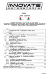
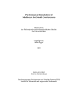
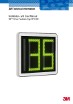
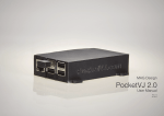
BOX
USER MANUAL
Thank you for purchasing our Powersafe sequential Coupling Unit.
The unit controls the connection sequence of incoming / out going cable connections.
The sequence ensures that the Earth connection is made first and disconnected last. (FMLB- First Mate
Last Break).
To connect cables to the unit
1: With key (included) turn the Earth lock clockwise (Fig 1). The Earth cover will pop open.
2: Raise the Earth cover fully open.
3: Take the Earth cable end connector (not included) and plug into the Earth position.
The Powersafe connectors are mechanically keyed to prevent connection errors. So it is not
possible to plug any other connector other than and Earth keyed connector into this
position.
4: To mate the connectors align the arrow on the mating connector with the green circle on the
Powersafe unit front panel. Push the connector fully into the box until it stops and then turn
clockwise.
5: The Neutral cover will now pop open.
6: Raise the Neutral cover to the fully open position. (Note when covers are raised the previous
connection cannot be disconnected without first closing the cover- for example when the Neutral cover
is raised the Earth connector cannot be removed)
7: Repeat steps 3-6 until all 5 connectors (E, N, L1,L2 &L3) are connected.
8: When the L3 connector is mated and turned fully clockwise to the locked position. Take the key
lock and turn the L3 lock clockwise. (Fig 2)
Turning this lock does two things.
a) It locks the L3 connector in place to prevent accidental disconnection under load and
prevents further access to the unit.
b) It switches an integral micro switch, which can be used as a signal path for electrical
protection device. A 3 pin connector plug is available which will plug onto the 3 pin connector
on the rear of the unit, to allow for connection of such devices (Fig 3)
To disconnect cables from the Unit
The disconnect sequence is reversed. Therefore the connectors have to be removed from Right to Left
starting with the L3 connector.
9: Turn L3 key lock anticlockwise to release the L3 connector.
10: Now turn the L3 connector fully anticlockwise and pull out of the port.
11: Push the cover down (note the cover will not fully close at this point, however with the cover
raised it will not be possible to remove the next connector.
12: Now turn the L2 connector fully anticlockwise and unplug (Note the L3 cover will
automatically fully close during this action)
13: Once all connectors are removed, turn the Earth key lock anticlockwise. This locks the Earth cover
preventing access to the unit.
BOX
Fig 1
The Earth lock prevents
unauthorised use of the unit.
Final lock prevents removal of
connectors from unit and
activates integral micro switch.
Locking Tool
Fig 2
Connector on rear panel for
connection of micro switch
cable
Micro switch lead connector
Fig 3
Technical Data
Overall Dimensions:
Option 1 : 2U rack mounting
Height 88mm, Length 483mm, Depth 130mm
Option 2 : Panel mounting
Height 108mm, Length 483mm, Depth 130mm
For this option add “108” to part number
Maximum Rated Voltage to Earth: 2KVac
Current Rating Up to 800A
Rear Terminals : M12 x 25 threaded studs
Micro Switch rating: 250VAC / 3A
Description
Panel Source Box (Green, Black, Red, Yellow, Blue, phase Coding)
Panel Source Box(Green, Blue, Brown, Black, Grey, phase Coding)
Panel Source Box(Green, Black, Red, White, Blue, phase Coding)
Panel Drain Box (Green, Black, Red, Yellow, Blue, phase Coding)
Panel Drain Box(Green, Blue, Brown, Black, Grey, phase Coding)
Panel Drain Box(Green, Black, Red, White, Blue, phase Coding)
Micro Switch Connector (Accessory)
Micro Switch Lead Assembly (Connector assembled with 1.5 meters of 3 core x
1mm jacketed cable)
Unlocking Tool (Spare)
Source Earth Dummy Plug ( Allows box to be used in 4 wire configuration
without Earth Position)
Drain Earth Dummy Plug ( Allows box to be used in 4 wire configuration
without Earth Position)
Part Code
PS5-UK
PS5-E
PS5-A
PD5-UK
PD5-E
PD5-A
MSPC-3P
MSCA-3P
UN-PSB
EDP-PSBS
EDP-PSBD
PSB with 108mm front panel
PSB with 2U 88mm front panel