1
Quartz Transducer Counting Interface AVA-07
22-Apr-2015
Page 1 of 7
1. INTRODUCTION
Quartz pressure/temperature transducers are widely used in the oil industry for measuring
downhole pressure and temperature with very high accuracy. Quartzdyne
(www.quartzdyne.com) is the leading manufacturer of quartz transducers, of which there
are two types: traditional Frequency Output Transducers (sometimes referred to as analog)
and the more recent Digital Transducers, which are accessed via an I²C interface.
The AVA-07 Quartz Transducer Counter offers a simple solution for converting a
traditional frequency output transducer into a digital transducer. It measures pressure and
temperature frequencies and returns the results through a Quartzdyne compatible I2C
interface. It can be thought of as a functional equivalent to Quartzdyne's counter FPGA
contained in a Digital Transducer. However, the AVA-07 is not pin compatible and there
are also some functional limitations regarding the I²C interface. The AVA-07 is not
intended as a replacement part inside a damaged Digital Transducer, but as an interface
between a Frequency Output Transducer and a data acquisition system designed for Digital
Transducers.
2. FUNCTIONAL DESCRIPTION
The AVA-07 is based on a 8051 microcontroller. The AVA-07 is clocked by the 7.2MHz
transducer reference and measures pressure and temperature frequencies via its internal
timers/counters.
The AVA-07 is configured via three wire links. Two of the links (A1, A2) determine the
I²C address, so that up to four circuits can be connected to a common I²C bus. The third
link (MODE) selects between two acquisition modes.
If the MODE link is removed, the AVA-07 employs a fixed gate time of 1sec over which
pressure and temperature frequencies are counted. However, the AVA-07 produces an
updated result every 91ms, i.e. the 1sec gate time can be thought of as a sliding acquisition
window that shifts every 91ms.
Figure 1: Sliding Acquisition Window
If the MODE link is inserted, the gate time is not fixed, but is automatically adjusted
between 91ms and 2.8sec according to the I²C query rate.
© Avanti Elektronik Limited - (44) 01224-583132 - www.avanti.clara.net - [email protected]
aqdq_11.doc
Quartz Transducer Counting Interface AVA-07
22-Apr-2015
Page 2 of 7
The AVA-07 measures pressure and temperature frequencies continuously and always
returns the most recent update when queried via the I²C Interface. In contrast to a Digital
Quartzdyne Transducer, the AVA-07 counters never overrun. Therefore no dummy reads
are required, even at very slow query rates.
3. APPLICATION CIRCUITS
The AVA-07 is available in a PLCC44 or a QFP44 package. In its most basic
configuration no further components are required, except for a 100nF decoupling capacitor
across the supply rail. However, depending on signal coupling and cable length some
additional components may be required as shown below.
Note that Fig.2 and Fig.3 show the PLCC package pinout, while Fig.4 and Fig.5 show the
QFP package pinout. It is essential that the 100nF decoupling capacitor is connected in the
shortest possible way to the GND and VCC pins of the device.
Figure 2: Basic application circuit. Suitable for DC coupled transducer signals and short connection
leads only (0.2m max at transducer end, 1m max at I²C end).
© Avanti Elektronik Limited - (44) 01224-583132 - www.avanti.clara.net - [email protected]
aqdq_11.doc
Quartz Transducer Counting Interface AVA-07
22-Apr-2015
Page 3 of 7
Figure 3: Application circuit with biasing for AC or DC coupled transducer signals. VCC and GND
connections of the biasing components should be routed directly to the 100nF decoupling capacitor.
Transducer and interface leads should be kept as short as possible (0.2m max at transducer end, 1m
max at I²C end)
Figure 4: Application circuit with biasing for AC or DC coupled transducer signals, terminated with
51R series resistors for use with slightly longer cables (0.5m max at transducer end, 2m max at I²C
end). Includes serial EEPROM for storing calibration coefficients.
© Avanti Elektronik Limited - (44) 01224-583132 - www.avanti.clara.net - [email protected]
aqdq_11.doc
Quartz Transducer Counting Interface AVA-07
22-Apr-2015
Page 4 of 7
Figure 5: Schematic of the Demo Board (AVA-07-DEMO), available ready built on FR4 circuit board.
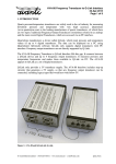
Figure 6: AVA-07-DEMO board measuring 2.75" x 0.7" (69.85mm x 17.78mm).
4. I²C INTERFACE
The implementation of the I²C Interface in Digital Quartzdyne Transducers is somewhat
unusual, as it occupies two separate device addresses, one for pressure and one for
temperature. This places a significant restriction on the implementation in a
microcontroller with byte wide I²C support.
Most microcontrollers, including the 8051 used in the AVA-07 can only respond to a
single device address at any given time, i.e. the microcontroller can be configured to
respond to a pressure query or to a temperature query, but not to both at the same time.
As a work around, the AVA-07 alternates between two I²C device addresses. It starts up
configured to respond to a pressure query. If it is queried for temperature, it does not
respond in that state. If it is queried for pressure, it returns the latest reading and then
© Avanti Elektronik Limited - (44) 01224-583132 - www.avanti.clara.net - [email protected]
aqdq_11.doc
Quartz Transducer Counting Interface AVA-07
22-Apr-2015
Page 5 of 7
reconfigures itself for a temperature query. The AVA-07 assumes that a pressure query is
always followed by a temperature query and vice versa.
The AVA-07 does support a control byte write access, but only if address bit A0 matches
the current device address configuration. A0 is marked as X (don't care) in the Quartzdyne
user manual, i.e. a control byte write access may be issued with A0=0 or A0=1. If the
control byte write access follows a pressure query, then A0 should be 1. If the control byte
write access follows a temperature query, then A0 should be 0. Otherwise the write access
will not be recognised. To ensure that a control byte access is successful, it can be issued
twice, once with A0=0 and once with A0=1. A control byte access does not alternate the
address configuration and therefore does not interfere with the normal sequence of
pressure and temperature queries.
A control byte write access sets a flag, causing the following read access to return the
status byte or the FPGA identifier instead of temperature or pressure data. However, the
AVA-07 only responds if configured for the correct device address at the time of the query.
Therefore, a FPGA identifier query can only work after a temperature query and a status
byte query only after a pressure query. Neither the FPGA identifier query nor the status
byte query alternate the address configuration and therefore do not interfere with the
normal sequence of pressure and temperature queries.
Writing to the control byte is needed to clear the write protection line (pin-7) of the serial
EEPROM shown in Fig.4 and Fig.5. This is only required, if the contents of the EEPROM
is to be changed. Reading from the EEPROM does not involve the control byte. Access to
the EEPROM itself is not affected by the limitations of the AVA-07. The EEPROM has its
own device address and operates independently.
I²C Command
Pressure query
Temperature query
Write to control byte
with A0 = 0
Write to control byte
with A0 = 1
Status byte query
FPGA identifier query
Table 1: I²C Summary
Condition
After power-up or preceded by a
temperature query
Preceded by a pressure query
Preceded by a pressure query
After power-up or preceded by a
temperature query
After power-up or preceded by a
temperature query
Preceded by a pressure query
Preceded by a pressure query
After power-up or preceded by a
temperature query
Preceded by a pressure query
After power-up or preceded by a
temperature query
After power-up or preceded by a
temperature query
Preceded by a pressure query
Result
Pressure data is returned
No response
Temperature data is returned
No response
Control byte is written
No response
Control byte is written
No response
Status byte is returned
No response
FPGA identifier is returned
No response
© Avanti Elektronik Limited - (44) 01224-583132 - www.avanti.clara.net - [email protected]
aqdq_11.doc
Quartz Transducer Counting Interface AVA-07
22-Apr-2015
Page 6 of 7
I²C Command
Read from EEPROM
Write to EEPROM
Condition
Always
Write protection cleared through
control byte access
Write protection is not cleared
Result
EEPROM data is returned
Data is written to EEPROM
Data is not written to EEPROM
Due to the I²C restrictions described above, it is not possible to guarantee that the AVA-07
will by default work with any acquisition system that works with Digital Quartzdyne
Transducers.
However, the AVA-07 has been tested to work with the AVA-03 Digital Quartzdyne
Tester and also with Quartzdyne's Q-Link interface, and generally should work with any
equipment that generates alternating pressure and temperature queries.
If in doubt, please contact Avanti for guidance.
Note that a complete 4-channel Frequency Transducer to Q-Link interface (Model No.
AVA-08) is also available, which includes 3V to 5V step up circuitry to support legacy
transducers.
5. RESOLUTION
The resolution of the pressure / temperature measurement depends on the gate time used
by the internal counters. Depending on the MODE link, the gate time is either fixed at 1sec
or self-adjusting between 91ms and 2.8sec according to the I²C query rate. The table below
summarises the resolution that can be expected for a number of different gate times.
Gate Time
0.091 sec
0.182 sec
0.273 sec
0.364 sec
0.455 sec
1.001 sec
1.456 sec
2.002 sec
2.821 sec
Table 2: Resolution versus Gate Time
Typical
Worst case
Typical
frequency
frequency
pressure
resolution (at
resolution (at
resolution of
50kHz)
70kHz)
10k transducer
(2.7Hz per psi)
Typical
pressure
resolution of
16k transducer
(2.4Hz per psi)
0.1526 Hz
0.0763 Hz
0.0509 Hz
0.0382 Hz
0.0305 Hz
0.0139 Hz
0.0095 Hz
0.0069 Hz
0.0049 Hz
0.0636 psi
0.0318 psi
0.0212 psi
0.0159 psi
0.0127 psi
0.0058 psi
0.0040 psi
0.0029 psi
0.0021 psi
0.2137 Hz
0.1068 Hz
0.0712 Hz
0.0534 Hz
0.0427 Hz
0.0194 Hz
0.0134 Hz
0.0097 Hz
0.0069 Hz
0.0565 psi
0.0283 psi
0.0188 psi
0.0141 psi
0.0113 psi
0.0051 psi
0.0035 psi
0.0026 psi
0.0018 psi
© Avanti Elektronik Limited - (44) 01224-583132 - www.avanti.clara.net - [email protected]
aqdq_11.doc
Quartz Transducer Counting Interface AVA-07
22-Apr-2015
Page 7 of 7
6. SPECIFICATION
Supply Voltage
Supply Current (excluding transducer)
Counting Reference
Update Rate
Gate Time
Package Options
Temperature Rating
2.7V – 5.5V (absolute maximum)
2.45mA @ 3.0V
2.85mA @ 5.0V
FREF / 2 = 3.6MHz
91ms
91ms – 2821ms (MODE link inserted)
1001ms (MODE link removed)
PLCC-44 and QFP-44
The device has a manufacturer's rating of 85°C.
Oven testing at 165°C is ongoing and the device
is still working fine after 6 months so far.
7. CAUTION
-
Double check wiring before powering up.
Do not exceed the maximum supply voltage of 5.5V. Use a current limited power
source if possible.
Do not apply power without a transducer or transducer simulator connected.
Avoid touching component pins and PCB pads to minimise the risk of damage through
electrostatic discharge (ESD).
8. ACKNOWLEDGEMENTS AND FURTHER INFORMATION
Quartzdyne is a trademark of Quartzdyne Inc.
Information on their range of pressure transducers can be downloaded from their web-site
at http://www.quartzdyne.com
The following document is of particular interest:
DigitalTransProg.pdf = Digital Transducer Programming Manual
I²C is a trademark of NXP Semiconductors (formerly Philips).
Specifications and application notes can be downloaded from their web-site at
http://www.nxp.com
The following document is of particular interest:
i2c.bus.specification.pdf = I²C Specification and User Manual Rev.03 / 2007
Avanti Part Number:
AVA-07-
Avanti Serial Number:
0001
Tested:
© Avanti Elektronik Limited - (44) 01224-583132 - www.avanti.clara.net - [email protected]
aqdq_11.doc