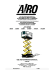
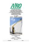
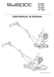
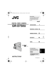
1
CARRELLO SEMOVENTE CON POSTO DI GUIDA ELEVABILE
SELF-PROPELLED TRUCK WITH ELEVATING OPERATOR POSITION
CHARIOT AUTOMOTEUR À POSTE DE CONDUITE ÉLEVABLE
SELBSTFAHRENDER WAGEN MIT ANHEBBAREM FAHRPLATZ
CARRETILLA AUTOPROPULSADA CON PUESTO DE CONDUCCIÓN ELEVABLE
ZELFRIJDENDE WAGEN MET HEFFENDE BESTUURDERSPLAATS
„MICRA“ SERIES
MICRA290
USE AND MAINTENANCE MANUAL
- ENGLISH AIRO is a division of TIGIEFFE SRL
Via Villasuperiore , 82 -42045 Luzzara (RE) ITALIA' +39-0522-977365 7 +39-0522-977015
WEB: www.airo.it
042.20.UEM-EN
03-2008
Tigieffe thanks you for purchasing a product of its range, and invites you to read this manual. Here you can find all the necessary
information for a correct use of the purchased machine; therefore, you are advised to follow the instructions carefully and to read
the manual thoroughly. The manual should be kept in a suitable place where no damage can occur to it. The content of this manual
may be modified without prior notice and further obligations in order to add changes and improvements to the units already
delivered. No reproduction or translation may take place without the written permission of the owner.
Contents:
1. INTRODUCTION.............................................................................................................................................................................4
1.1
Legal aspects ...........................................................................................................................................................................................4
1.1.1 Delivery of the unit ..............................................................................................................................................................................4
1.1.2
Periodical checks.............................................................................................................................................................................4
1.1.2.3
Transfers of Ownership ...............................................................................................................................................................4
1.2
Intended use.............................................................................................................................................................................................4
1.3
Description of the unit...............................................................................................................................................................................5
1.4
Control stations.........................................................................................................................................................................................5
1.5
Power supply ............................................................................................................................................................................................5
1.6
Identification .............................................................................................................................................................................................6
1.7
Location of main components...................................................................................................................................................................7
2. TECHNICAL FEATURES OF STANDARD MACHINES (DIMENSIONS AND PERFORMANCE) .................................................8
2.1
2.2
Dimensions...............................................................................................................................................................................................8
Performance.............................................................................................................................................................................................9
3. SAFETY PRECAUTIONS ..............................................................................................................................................................10
3.1 Power supply ................................................................................................................................................................................................10
3.2
Work and maintenance rules..................................................................................................................................................................10
3.3
Safety rules.............................................................................................................................................................................................11
3.3.1
General..........................................................................................................................................................................................11
3.3.2
Handling.........................................................................................................................................................................................11
3.3.3
Operating procedures....................................................................................................................................................................12
4. INSTALLATION AND PRELIMINARY CHECKS...........................................................................................................................13
4.1
Before using the machine.......................................................................................................................................................................13
5. GENERAL USE INSTRUCTIONS..................................................................................................................................................14
5.1
Operator position....................................................................................................................................................................................14
5.1.1
Drive and steering..........................................................................................................................................................................15
5.1.2
Operator position lowering / lifting .................................................................................................................................................16
5.1.3
Mobile loading surface lowering / lifting .........................................................................................................................................17
5.1.4
Other functions ..............................................................................................................................................................................17
5.1.4.1
Emergency STOP button (E).....................................................................................................................................................17
5.1.4.2
Battery indicator and hourmeter (L)...........................................................................................................................................18
5.2
Electric power unit ..................................................................................................................................................................................19
5.3
Access to operator position ....................................................................................................................................................................20
5.4
Start-up...................................................................................................................................................................................................20
5.5
Lifting and carrying loads........................................................................................................................................................................21
5.5.1
Mobile loading surface and ground loading space ........................................................................................................................21
5.5.2
Lifting and carrying loads on the mobile loading surface...............................................................................................................22
5.5.3
Carrying the loads on the ground loading space ...........................................................................................................................23
5.6
Machine stop ..........................................................................................................................................................................................24
5.6.1
Normal stop ...................................................................................................................................................................................24
5.6.2
Emergency stop.............................................................................................................................................................................24
5.7
Manual emergency lowering control.......................................................................................................................................................25
5.8
End of working session...........................................................................................................................................................................25
6. HANDLING AND CARRYING........................................................................................................................................................26
6.1
6.2
6.3
Handling .................................................................................................................................................................................................26
Carrying..................................................................................................................................................................................................26
Machine emergency removal .................................................................................................................................................................27
7. MAINTENANCE.............................................................................................................................................................................28
7.1
Machine cleaning....................................................................................................................................................................................28
7.2
General maintenance .............................................................................................................................................................................29
7.2.1
Various adjustments ......................................................................................................................................................................30
7.2.2
Greasing ........................................................................................................................................................................................31
7.2.3
Hydraulic circuit oil level check and change ..................................................................................................................................31
7.2.4
Hydraulic filter replacement ..........................................................................................................................................................32
Use and maintenance manual
Self-propelled aerial platforms
Page 2
7.2.5
Inclinometer operation check and adjustment ...............................................................................................................................32
7.2.6
Operation check and adjustment of overload controller ................................................................................................................33
7.2.7
Safety micro-switches operation check .........................................................................................................................................34
7.2.8
“Dead-man” switch operation check ..............................................................................................................................................34
7.2.10
Battery ...........................................................................................................................................................................................35
7.2.10.1 General warning instructions.....................................................................................................................................................35
7.2.10.2 Battery maintenance ................................................................................................................................................................35
7.2.10.3 Battery recharge........................................................................................................................................................................36
7.2.10.3.1 Battery charger: safety devices and fault reports..............................................................................................................37
7.2.10.4 Battery replacement ..................................................................................................................................................................37
8. MARKS AND CERTIFICATIONS .................................................................................................................................................38
9. CHECK REGISTER ......................................................................................................................................................................38
Use and maintenance manual
Self-propelled aerial platforms
Page 3
1. INTRODUCTION
This Use and Maintenance Manual provides general instructions concerning the complete range of units indicated on the cover.
Therefore the description of their components, as well as control and safety systems, may include parts not present on your unit
since supplied on request or not available. In order to keep pace with the technical development AIRO-Tigieffe s.r.l. reserves the
right to modify the product and/or the use and maintenance manual at any time without updating the units already delivered.
1.1
Legal aspects
1.1.1
Delivery of the unit
Within EU (European Union) member countries the machine is delivered complete with:
- Use and Maintenance manual in your language;
- CE mark applied on the unit;
- CE conformity declaration.
Please remember that the Use and Maintenance Manual is an integral part of the machine and a copy of this, together with copies
of the documents certifying that the periodical checks have been carried out, should be available to the operator. In the event of a
transfer of property the machine must always be provided with its use and maintenance manual.
1.1.2
Periodical checks
The legal obligations of the owner of the machine vary according to the country of commissioning. It is therefore recommended to
inquiry about the procedures in force in your country from the boards responsible for industrial safety. The employer should entrust
maintenance (at least every year) to skilled personnel. This manual contains a final section called "Check Register" for a better
filing of documents and recording of any modifications/service.
1.1.2.3
Transfers of Ownership
Should the ownership of the truck be transferred, the new owner is to be supplied with:
- Conformity declaration issued by the manufacturer;
- Instructions manual.
1.2
Intended use
The machine described in this manual is a SELF-PROPELLED TRUCK WITH ELEVATING OPERATOR POSITION AND FREE
DRIVE, and has been designed for lifting / carrying:
- material (in the areas named MOBILE LOADING SURFACE and GROUND LOADING SPACE)
- the operator (at the elevating operator position).
The TRUCK is intended especially for manual operations of collection, loading, unloading of packed materials and/or materials of
homogeneous shape with reduced dimensions and weight. The maximum allowed capacity is divided as follows:
- 90 kg. of material on the mobile loading surface;
- 130 kg. of material on the ground loading space;
- 120 kg at the operator position (elevating operator position).
It is absolutely forbidden to exceed the maximum allowed capacities indicated by the plate on the elevating operator position. The
operator position can be accessed only from the access position, i.e. with operator position completely lowered. It is absolutely
forbidden to access the operator position not in access position.
The loads must be placed within the perimeter of the MOBILE LOADING SURFACE and/or within the perimeter of the GROUND
LOADING SPACE. Occasionally, loads of bigger dimensions are allowed to be lifted provided the maximum capacity is suitably
reduced and the load is secured as indicated in the following chapters. It is not allowed to lift loads hanging from the lifting
structures, even if the maximum capacity is observed.
The truck can be used indoors only (with no wind whatsoever) on horizontal and flat floor, without obstacles, holes and steps and in
sufficient lighting conditions.
Use and maintenance manual
Self-propelled aerial platforms
Page 4
When the unit is moving with lifted operator position do not load horizontal loads (the operator on board must not pull ropes, cables,
etc.).
A load control system interrupts the normal operation of the unit if the lifted load exceeds by 25% approx. the rated load with lifted
operator position (see chapter "General use rules”).
The unit cannot be used in areas where road vehicles operate. Always surround the working area by means of suitable signs when
the unit is used in public areas.
The machine is not intended for towing trucks or other vehicles.
1.3
Description of the unit
The machine described in this use and maintenance manual is a SELF-PROPELLED TRUCK WITH ELEVATING OPERATOR
POSITION AND FREE DRIVE consisting of:
- motorized chassis equipped with wheels;
- vertical telescopic lifting structure operated by one hydraulic cylinder;
- operator platform (operator position);
- MOBILE LOADING SURFACE for material lifting/handling.
The truck is motorised to allow the machine to move ( see General use instructions”) and has two rear driving wheels and two front
idle pivoting wheels. Steering is possible thanks to a differentiated control between the right drive geared motor and left drive
geared motor. Automatic braking is guaranteed by the irreversibility of both drive geared motors.
The hydraulic lifting cylinder of the telescopic extension structure is single-acting, therefore the lowering movement of the operator
position occurs by gravity. The cylinder has a solenoid safety valve directly flanged on the same. This feature allows the loads to
be kept in position (elevating operator position and loading surface) even if the supply tube accidentally breaks.
The elevating operator position (or platform) is equipped with guard-rails and toe-boards of a prescribed height (the height of the
guard-rails is ≥ 1100 mm; the height of the toe-boards is ≥ 150 mm).
The mobile loading surface is secured to the front part of the platform (operator position) and can be lifted/lowered by means of an
irreversible electro-mechanical jack controlled by the operator from the operator position.
1.4
Control stations
The machine is equipped with two control stations:
- on the platform (elevating operator position) for normal use of the unit;
- on the chassis where you can find the emergency controls for operator position recovery and emergency stop. The same
emergency button is fitted with a removable key to start the machine.
1.5
Power supply
The machine is powered by an electro-hydraulic system consisting of rechargeable accumulators, electric geared motors and
electric pump. Both the hydraulic and the electric systems are equipped with all necessary protections (see electric and hydraulic
circuit diagrams annexed to this manual).
Do not use the machine for purposes different from those it was intended for.
If disposal of the unit is necessary, comply with current local regulations.
Use and maintenance manual
Self-propelled aerial platforms
Page 5
1.6
Identification
In order to identify the machine, when spare parts and service are required, always mention the information given in the serial
number plate. Should this plate (as well as the various stickers applied on the unit) be lost or illegible, it is to be replaced as soon
as possible. In order to identify the machine when no plate is available the serial number is also stamped on the chassis. To locate
the plate and the stamp of the serial number, see the following picture. The main data of the machine to which this book refers are
indicated in the following boxes:
Model.................................…………..
Chassis:..................................………...
Year:...................................…………...
Fig. 1
Use and maintenance manual
Self-propelled aerial platforms
Page 6
1.7
Location of main components
1) Mobile loading surface;
2) Bubble level for visual check of machine
inclination;
3) Mechanical jack and linear guides;
4) Ground-loading space;
5) Flashing indicator light and sensor
buzzer;
6) Pivoting wheels;
7) Driving wheels and drive geared motors;
8) 230V battery-charger power socket;
9) Emergency lowering control lever;
10) Ground chassis with
Electric pump;
Lower control solenoid valve;
Microswitch M1;
Batteries;
Inclinometer;
Battery charger;
Electric power unit.
11) Telescopic lifting structure and lifting
cylinder;
12) Retractable ladder;
13) Controls;
14) Platform (elevating operator position);
15) M3 microswitch (lifting limit switch).
Fig.2
Use and maintenance manual
Self-propelled aerial platforms
Page 7
2. TECHNICAL FEATURES OF STANDARD MACHINES (DIMENSIONS AND PERFORMANCE)
2.1
Dimensions
Fig.3
Use and maintenance manual
Self-propelled aerial platforms
Page 8
2.2
Performance
Description
Q1 - Max. capacity of mobile loading surface - kg Q2 - Max. capacity of operator position - kg Q3 - Max. capacity of ground loading space - kg Max. no. of people allowed at operator position
Max. drive height
Dimensions of pivoting wheels - mm Dimensions of driving wheels - mm Max. operating temperature - °C Min. operating temperature - °C Stability limits:
Longitudinal inclination - degrees Transversal inclination - degrees Max. wind force - m/s STANDARD Battery voltage and capacity –V/AhSTANDARD battery weight - kg OPTIONAL Battery voltage and capacity –V/AhOPTIONAL battery weight - kg Single-phase battery charger - V/A Max. current absorbed by battery charger -ALifting electric pump power - W Max. absorbed current - A Max. hydraulic pressure - bar Power of electric drive motors (N.2) - W Max. absorbed current each one - A Power of electric motor for mobile loading surface lifting - W Max. absorbed current - A Max. lifting speed of operator position - m/s Max. lowering speed of operator position - m/s Max. lifting speed of mobile loading surface - mm/s Max. lowering speed of mobile loading surface - mm/s Max. drive speed - m/s Drive safety speed - m/s Hydraulic oil tank capacity - l Max. gradeability - % Volume - m3 Machine weight (unloaded) - Kg -
MICRA290
90
120
130
1
Max. (A)
Ø200 x 50
Ø200 x 50
-5
+50
2
2
0 (B)
24 / 70
45
24 / 85
95
24 / 15
2
2000
105
40
300
18,5
150
8,5
0,13
0,16
65
65
0,71
0,22
20
25
1,6
405 (C)
(A) Possible travel with operator position and mobile loading surface completely lifted.
(B) Machine to be used indoors (with no wind whatsoever).
(C) Weight with optional battery = 455 kg.
Noise tests have been carried out under the most unfavourable conditions to study the effects on the operator. The level of acoustic pressure
weighed (A) at work places does not exceed 70dB(A).
As to vibrations in ordinary working conditions:
- the rms. value weighed according to acceleration frequency relevant to the upper limbs is lower than 2.5 m/sec 2 ;
- the rms. value weighed according to acceleration frequency relevant to the body is lower than 0.5 m/sec 2 .
Use and maintenance manual
Self-propelled aerial platforms
Page 9
3. SAFETY PRECAUTIONS
3.1 Power supply
The electric and hydraulic circuits are provided with safety devices, calibrated and sealed by the manufacturer.
Do not tamper with and modify the calibration of any component of the electric and hydraulic system.
3.2
-
-
Work and maintenance rules
The machine must be used only in areas well lit up, checking that the ground is flat and firm. The machine may not be used if
the lighting conditions are not sufficient.
The machine must be used indoors only (with no wind whatsoever).
Before using the machine check its integrity and conservation state.
During maintenance operations do not dispose of any waste materials in the environment, but comply with current regulations.
Do not carry out any service or maintenance operations when the machine is connected to the power supply. Follow the
instructions given in the following paragraphs.
Do not approach the electric and hydraulic system components with sources of heat or flames.
While using the machine, comply with the current local regulations relevant to this class of machines.
Do not increase the max. allowed height of the operator position by means of scaffolds, ladders or other.
Do not use the machine as a crane.
Do not use the machine as a lift.
The machine must be stocked or parked indoors only, protected against atmospheric agents.
Do not use the machine in areas where risks of fire or explosion exist.
Do not use pressurized water jets (high-pressure cleaners) to wash the machine.
The machine can be used in warehouses with limited height only, so that the operator can keep the stability of the stocked
material under control.
Use and maintenance manual
Self-propelled aerial platforms
Page 10
3.3
Safety rules
3.3.1
General
Only adults, after carefully reading this manual and properly trained, are allowed to use the machine (the
employer must supply instructions and information concerning the use of the machine) .
Do not leave the truck unattended with ignition keys inserted.
Use the machine at a distance of at least 5 metres from high-tension lines (in any case not in proximity to
live elements).
Use the machine according to the capacity values indicated in the technical features section. The
identification plate indicates the max. allowed number of people at the operator position.
It is absolutely forbidden to access the elevating operator position not in access position.
It is the machine owner and/or safety manager’s responsibility to check that the operators have been
thoroughly trained in the use of the machine.
It is the machine owner and/or safety manager’s responsibility to check that the maintenance and repair
operations are carried out by skilled personnel.
3.3.2
Handling
Before any movement make sure that any machine plugs are disconnected from the power source.
In order to avoid any instability, use the machine on regular and firm grounds. Before lifting the operator
position, check its level through the spirit level. To prevent the machine from overturning, comply with
the max. gradeability values indicated in the Technical features section under paragraph "Stability limits".
However, movements on inclined grounds are to be carried out with the utmost caution.
As soon as the operator position is lifted, the drive safety speed is automatically activated.
Drive the unit with lifted operator position only on flat grounds, verifying the absence of holes or steps on
the floor and bearing in mind the overall dimensions of the unit.
While driving the unit with lifted operator position the operator is not allowed to place horizontal loads onto
the operator position (the operator on board must not pull ropes, wires, etc.).
The machine must not be used directly on roads.
Do not use the machine for people carriage (see paragraph 1.2 “Intended use”). The only person on board
is the operator at the operator position.
Movements on upward or downward ramps can be carried out only with lowered operator position and
with load well secured to the loading surface.
Carry out movements on ramps with max. slope not exceeding the one indicated at chapter “2
TECHNICAL FEATURES”.
Do not lean over the operator position rails.
It is forbidden to use the truck as a towing device.
Check that in the operating area there are not obstacles or other dangerous elements.
Pay particular attention to the area above the machine during lifting to avoid any crushing and collisions.
Use and maintenance manual
Self-propelled aerial platforms
Page 11
3.3.3
Operating procedures
The machine is fitted with a load control system which, with lifted operator position, stops the lifting
movement of the operator position when overloaded (the controlled load is given by the amount of the
load at the operator position and that on the loading surface). Machine operation can be resumed only
after removing the exceeding load.
The machine is equipped with an inclination control system which, with lifted operator position, stops
drive and lifting of the operator position in case of unstable position. Working operations can be resumed
only after placing the machine in a steady position with the lower control of the operator position. Should
the audible device turn on, the machine is not correctly positioned (see paragraphs relevant to general
use instructions). Bring operator position to safety rest position before resuming operations.
The entry gates of the operator position are fitted with microswitches for controlling the closed position.
When the gates are not perfectly closed all machine controls are disabled.
Do not lean over the operator position rails.
Do not wear baggy or hanging clothes.
During operations in public areas surround the working area by means of barriers or other suitable signs.
Make sure that no people, apart from the operator, are in the area where the machine is operating. While
moving the truck from the operator position the operator should pay particular attention to avoid any
contact with the personnel or other vehicles on the ground.
Lift the operator position only if the machine is resting on solid and flat surfaces. Drive the machine with
lifted operator position only if the ground is solid and flat.
After each work session, always take the keys out of the control panel and keep them in a safe place to
prevent unauthorized people from using the machine.
The lifted loads on the loading surface should be held within the surrounding edges of its surface.
Occasionally, loads of bigger dimensions are allowed to be lifted provided the maximum capacity is
suitably reduced and the load is secured as indicated in the following chapters.
Only lift packed loads of homogeneous shape and composition and of weight not exceeding the max.
allowed load.
It is forbidden to lift persons who are outside the operator position.
Use and maintenance manual
Self-propelled aerial platforms
Page 12
4. INSTALLATION AND PRELIMINARY CHECKS
The machine is supplied completely assembled, therefore it can perform all functions in full safety as provided for by the
manufacturer. No preliminary operation is required. To unload the machine, follow the instructions in paragraph “Handling and
carrying”.
Place the machine onto a firm ground and with a gradeability lower than the max. allowed (see “Stability limits”). The machine is
equipped with a bubble level on the operator position for visual check and inclinometer on the chassis to always check machine
levelling, both transversal and longitudinal.
Before using the machine read the instructions given in this manual and the concise instructions indicated on the machine plate.
Before starting any operations verify the integrity of the unit (by means of a visual check) and read the plates indicating the
operating limits.
4.1
Before using the machine
Before using the machine the operator must always check visually that:
-
the battery is completely charged;
the oil level lies between the min. and max. value (with lowered operator position);
the machine carries out all operations in safety;
the wheels and drive motors are properly fixed;
the wheels are in good condition;
the rails and closing bar of the operator position are properly secured;
the structure does not show clear faults (check welding of lifting structure);
the instructions plates are perfectly readable;
the controls are perfectly efficient both from the operator position and the ground emergency control post, including the “deadman” system.
Use and maintenance manual
Self-propelled aerial platforms
Page 13
5. GENERAL USE INSTRUCTIONS
Before using the machine read this chapter thoroughly.
Follow exclusively the instructions given in the next paragraphs and the safety rules described both hereafter
and in the previous paragraphs. Read the next paragraphs carefully in order to properly understand the
on/off procedures as well as all operations and their correct use.
Before any movement, verify the presence of people in close proximity to the machine and, in any case,
proceed with the utmost caution.
5.1
Operator position
A) Dead-man Pedal;
B) Steering switch;
C) Drive control handle (forward/reverse
drive);
D) Emergency stop button;
E) Movement enable sensor;
F) Bubble level;
G) Operator position lifting button;
H) Operator position lowering button;
I) Free / straight drive selector;
L) Battery indicator / Hourmeter;
M) Loading surface lifting button;
N) Loading surface lowering button;
O) Gate position control microswitches.
For safety reasons, before using all the
controls, press the Dead-man Pedal A and
keep your left hand on sensor E.
If Pedal A and/or sensor E are accidentally
released while the machine is operating, the
movement is immediately stopped.
Fig.4
AUTO-TURNING OFF
If the machine is inactive for a few minutes, the control system disables automatically.
To resume the operations press and activate the STOP button (D) once again.
GATES POSITION
All movements are disabled if the gates are not perfectly closed.
CAUTION!
Keeping the sensor (E) active for over 10 seconds without carrying out any operation will disable the control
station. To operate the machine again, remove and reposition your left hand on the movement enable sensor
(E).
Use and maintenance manual
Self-propelled aerial platforms
Page 14
5.1.1
Drive and steering
The following controls are to be used to move the machine:
- Dead-man Pedal A;
- Movement enable sensor E;
- Drive handle C;
- Steering switch B.
To drive the unit, press the Dead-man Pedal A first and reposition your left hand on the enable sensor E, then operate the
proportional drive handle C and/or the steering switch B.
For a straight drive, activate the control handle C, turning it forward for forward drive or backward for reverse drive as shown in the
following figure.
Fig.5
To steer the unit, activate the steering switch B. Press it on the left for left steering; press it on the right for right steering.
The steering switch is of proportional type; the extent of steering can be adjusted according to the pressure exerted on the switch.
Fig.6
By completely activating the steering switch and drive handle at the same time (movement steering), you get a zero steering radius
(one of the driving wheels is still and matches the rotation axis of the machine).
By completely activating the steering switch without activating the drive handle (steering from still position), the machine rotates on
itself allowing a rapid drive reversal in narrow spaces.
Use and maintenance manual
Self-propelled aerial platforms
Page 15
Set the “free / straight drive selector” I to position 2 to freely control drive as wished. Set the
“free / straight selector” I to position 1 to lock the front steering wheels in straight position
for easier straight drive by simultaneously using the control handles B and C. The locking
system of the steering wheels can be activated in any wheel position, but due to the special
mechanical structure of the system, it definitely locks the steering wheels only when they
are oriented longitudinally.
Fig.7
With operator position completely lowered, drive speed can be adjusted up to max. speed. With operator position lifted
the safety drive speed is automatically activated.
It is forbidden to drive the truck when the operator position is lifted unless the ground is flat and firm enough.
Drive is forbidden with raised operator position while carrying loads on the mobile loading surface. Drive with
loads on the mobile loading surface is possible only with operator position completely lowered.
Before any movement, verify the presence of people and/or other equipment in close proximity to the
machine and, in any case, proceed with the utmost caution.
Drive the unit with lifted operator position only on flat grounds, verifying the absence of holes or steps on
the floor and bearing in mind the overall dimensions of the unit.
While driving the unit with lifted operator position the operator is not allowed to place horizontal loads (the
operator on board must not pull ropes, wires, etc.).
5.1.2
Operator position lowering / lifting
The following controls are to be used to lift and lower the operator position:
- Dead-man Pedal A;
- Movement enable sensor E;
- Operator position lifting button G;
- Operator position lowering button H;
To lift the operator position press the Dead-man Pedal A first, position your left hand on the enable sensor E and press the lifting
button G.
To lower the operator position press the Dead-man Pedal A first, position your left hand on the enable sensor E and press the
lowering button G.
Fig.8
Use and maintenance manual
Self-propelled aerial platforms
Page 16
5.1.3
Mobile loading surface lowering / lifting
The following controls are to be used to lift and lower the mobile loading surface:
- Dead-man Pedal A;
- Movement enable sensor E;
- Loading surface lifting button M;
- Loading surface lowering button N;
To lift the loading surface press the Dead-man Pedal A first, position your left hand on the enable sensor E and press the lifting
button M.
To lower the loading surface press the Dead-man Pedal A first, position your left hand on the enable sensor E and press the
lowering button N.
Fig. 9
For further instructions on how to lift and carry loads see chapter “5.5 Lifting and carrying loads”.
Do not lower the mobile loading surface with lowered operator position if other material is present on the
ground loading space.
5.1.4
Other functions
5.1.4.1
Emergency STOP button (E)
By pressing the red STOP button all control functions are interrupted. Normal functions are
enabled by rotating the button of 1/4 turn clockwise (as indicated in position B).
In case of fault, press the red stop button to RESET the system.
If the machine is inactive for a few minutes, the control system disables automatically.
To resume the operations press and activate the STOP button once again.
Fig.10
Use and maintenance manual
Self-propelled aerial platforms
Page 17
5.1.4.2
Battery indicator and hourmeter (L)
It indicates the charge level of the battery and the working hours of the machine. The
voltmeter and hourmeter are active only when the machine is turned on and the dead-man
pedal pressed.
If all the red leds are lit, battery charge is approximately 100%. If only the first two leds are
flashing, the battery charge has exceeded the minimum charge level (approximately 20%). In
this condition operator position lifting is automatically disabled. The battery must be
immediately recharged. However, battery should be recharged daily, either at night or during
long work intervals.
Fig.11
Use and maintenance manual
Self-propelled aerial platforms
Page 18
5.2
Electric power unit
The electric power unit contains the electronic system necessary to operate the machine and to carry out safety checks, and is
located on the chassis (see paragraph "Location of main components").
On the electric power unit you can find the emergency STOP button / ON-OFF key, to start and stop the machine during ordinary
use and in case of emergency.
By turning the key by a 1/2 of turn clockwise and pulling to the outside, the red
STOP button is released and the machine is accordingly started. In this position you
can remove the key.
Fig. 12
By pressing the push-button the machine turns off. When the push-button is
pressed, you can remove the key.
Fig. 13
Access to the electric power unit is allowed to specialized personnel only for maintenance and/or repair
purposes. Access the electric power unit only after the machine has been disconnected from any 230V power
sources.
The key must be given to authorized personnel. Keep a duplicate key in a safe place.
At the end of the working session, press the push-button and always remove the ON-OFF key.
On the electric power unit you can also find an audible alarm and a flashing warning light which are enabled:
- during lifting/lowering of the operator position (warning of moving machine);
- during forward/backward drive (warning of moving machine);
- in case of overload alarm (alarm);
- in case of inclination alarm (alarm).
Use and maintenance manual
Self-propelled aerial platforms
Page 19
5.3
Access to operator position
To access the operator position use only the access
equipment the machine is provided with.
To access the operator position:
- lower ladder A;
- open gates B and get on board.
Check that once on the operator position, the gates are perfectly
closed.
All movements are disabled if the gates are not
perfectly closed.
Fig.14
5.4
Start-up
To allow the machine to be turned on, the 230V power plug must be disconnected so that battery charger is
off (see paragraph concerning battery charge).
If the electric line is connected (battery charger on), the machine is off and cannot be turned on.
To start the machine the operator shall:
- Turn the on/off key of the electrical power unit by ½ of turn;
- Pull the red STOP button to the outside.
- Remove the ON-OFF key and keep it in a safe place or hand it over to a person
in charge on ground, properly informed of the use of the emergency controls;
- Get onto the operator position;
- At the operator position (see previous paragraphs) release the stop button;
- Perform the various functions by thoroughly following the instructions given in
the previous paragraphs.
Fig. 15
Use and maintenance manual
Self-propelled aerial platforms
Page 20
5.5 Lifting and carrying loads
CAUTION! Follow the instructions of this chapter to avoid any instability risks and material fall.
The TRUCK is intended especially for manual operations of collection, loading, unloading of packed materials
and/or materials of homogeneous shape with reduced dimensions and weight. The maximum allowed capacity
is divided as follows:
- 90 kg. of material on the mobile loading surface;
- 130 kg. of material on the ground loading space;
- 120 kg at the operator position (elevating operator position).
It is absolutely forbidden to exceed the maximum allowed capacities indicated by the plate on the elevating
operator position.
The loads must be placed within the perimeter of the MOBILE LOADING SURFACE and/or within the perimeter
of the GROUND LOADING SPACE. Occasionally, loads of bigger dimensions are allowed to be lifted provided
the maximum capacity is suitably reduced and the load is secured as indicated in the following chapters.
IT IS FORBIDDEN to lift/carry loads hanging from the lifting structures, even if the maximum capacity is
observed.
IT IS FORBIDDEN to lift/carry unstable loads.
IT IS ABSOLUTELY FORBIDDEN to lift or carry people on those machine parts intended for lifting/carrying
materials.
Fig.16
5.5.1
Mobile loading surface and ground loading space
The picture aside shows the main components of the MOBILE LOADING SURFACE
and the GROUND LOADING SPACE.
A – Ground loading space
B – Mobile loading surface
C – Folding side boards to hold the loads.
Fig. 17
Use and maintenance manual
Self-propelled aerial platforms
Page 21
5.5.2
Lifting and carrying loads on the mobile loading surface
It is absolutely forbidden to exceed the maximum allowed capacities indicated by the plate on the elevating
operator position.
Loads must be placed within the perimeter of the mobile loading surface. Occasionally, loads of bigger
dimensions are allowed to be lifted provided the maximum capacity is suitably reduced and the load is
secured as indicated below.
Only lift/carry packed materials and/or materials with homogeneous shape and reduced dimensions and
weight.
Drive is forbidden with raised operator position while carrying loads on the mobile loading surface. Drive with
loads on the mobile loading surface is possible only with operator position completely lowered.
Do not lower the mobile loading surface if other material is present on the ground loading space.
To lift/carry loads on the MOBILE LOADING SURFACE:
a) Approach the shelves/exhibitor where the material to be collected is
placed, using the controls as indicated in the previous chapters;
b) To drag the loads from the shelves/exhibitor to the loading surface,
lower the folding side board close to the shelf and lift or lower the
loading surface up to the same level of the shelf/exhibitor; lift the other
two side boards to minimize the risk of load fall;
c) Drag/place the load onto the loading surface checking the perfect
stability (if necessary, loads of large dimensions can be secured by
tying them through holes A);
d) Lower the operator position;
e) Lower the operator position for a safe view of the path to be covered by
the machine.
f) Position the machine near the new spot where the material has been
previously collected.
g) Unload the previously loaded material to the new spot by following the
above instructions in the reverse order.
Fig. 18
Fig.19
Use and maintenance manual
Self-propelled aerial platforms
Page 22
5.5.3
Carrying the loads on the ground loading space
It is absolutely forbidden to exceed the maximum allowed capacities indicated by the plate on the elevating
operator position.
Carry only packed materials and/or materials with homogeneous shape and reduced dimensions and weight.
Loads must be placed within the perimeter of the ground loading space. Occasionally, loads of bigger
dimensions are allowed to be lifted provided the maximum capacity is suitably reduced and the load is
secured as indicated below.
Do not lower the mobile loading surface if other material is present on the ground loading space.
On the GROUND LOADING SPACE only packed materials and/or
materials with homogeneous shape and reduced dimensions can be
carried, checking the stability before any machine movement.
Loads of large dimensions can be lifted (if they are within the loading
space) by lifting the mobile loading surface as indicated below. Any
loads of large dimensions are to be secured by tying them through
holes A.
Fig. 20
Fig.21
Use and maintenance manual
Self-propelled aerial platforms
Page 23
5.6
Machine stop
5.6.1
Normal stop
In normal operating conditions:
- By releasing the controls the operation is stopped. Stop occurs within a time limit set in the factory, which guarantees smooth
braking.
5.6.2
Emergency stop
Should it be necessary, the operator may immediately stop all machine functions from both the operator position and ground
control station.
From the operator position:
- press the operator position push-button and all controls will be neutralised;
From the ground control station:
- press the ground control station stop button and the machine will be turned off;
To resume the operations:
From the operator position:
- turn the stop button of 1/4 turn clockwise;
From the ground control station:
- turn the on/off key of the electric power unit by ½ of turn and pull the red STOP button to the outside.
Use and maintenance manual
Self-propelled aerial platforms
Page 24
5.7
Manual emergency lowering control
This function is to be used only in emergency situations when no motive power to lower the operator position
is available.
In case of fault in the electric or hydraulic system, carry out the following emergency
procedures:
-
Pull the emergency lever A to the outside;
Check the correct execution of the lowering movement and make sure nobody
is within the lowering trajectory.
WARNING: THE EMERGENCY LOWERING CONTROL CAN BE STOPPED AT
ANY TIME BY RELEASING LEVER “A”.
Fig. 22
5.8
End of working session
After stopping the machine according to the instructions given in the previous paragraphs:
- position the machine in a safe place, on flat and strong enough ground;
- always set the operator position to rest condition (completely lowered);
- press the Stop button of the ground electric power unit;
- remove the keys to prevent unauthorized people from using the machine;
- recharge the battery according to the instructions given in section "Maintenance".
Use and maintenance manual
Self-propelled aerial platforms
Page 25
6. HANDLING AND CARRYING
6.1
Handling
To handle the machine in normal operating conditions follow the instructions given in chapter "GENERAL USE INSTRUCTIONS"
under paragraph "Drive and steering”.
When the operator position is completely lowered, the machine can be handled (i.e. drive can be performed) at different speeds to
be freely selected by the user.
When the operator position is lifted, the drive safety speed is automatically activated.
It is absolutely forbidden to drive the unit when the operator position is lifted unless the ground is horizontal,
flat and steady.
Check that there are no holes or steps on the floor and bear in mind machine overall dimensions.
Before any movement, verify the presence of people in close proximity to the machine and, in any case,
proceed with the utmost caution.
Before any movement make sure that any machine plugs are disconnected from the power source.
When the unit is moving with lifted operator position do not load horizontal loads (the operator on board must
not pull ropes, cables, etc.).
6.2
Carrying
In order to carry the machine to the various working sites, follow the instructions given below.
Before carrying it is recommended to inquire about the overall dimension limits for road transport in force in your country.
Before carrying the machine, turn it off and remove the keys from the control panels.
No people are allowed in proximity to or on the machine to avoid any risks deriving from sudden movements.
For safety reasons never lift or tow the machine by means of its booms or operator position.
Loading operations are to be carried out on a flat surface with a suitable capacity, after setting the operator
position to rest condition.
Before carrying the unit secure the machine to the loading surface properly.
To carry the machine the operator shall load it onto a vehicle either:
1) By means of chutes and translation controls located on the operator position to load it directly onto the vehicle - if ramp
slope is within the gradeability described in paragraph “TECHNICAL FEATURES” and capacity is adequate to weight according to the instructions given in chapter “GENERAL USE INSTRUCTIONS” under paragraph “Drive and steering” for the
correct operation of drive controls.
2) By means of a lift truck of a suitable capacity (see machine weight in table “Technical features” at the beginning of this
manual) equipped with forks having at least the same length as the machine width. Insert the forks as indicated by the stickers
on the machine. Should these stickers be not available, DO NOT lift the machine by means of a lift truck. Lifting the unit by
means of a lift truck must be carried out by qualified operators.
Use and maintenance manual
Self-propelled aerial platforms
Page 26
After placing the machine onto the carrying vehicle, fasten it with ropes/bands tied to the operator position
handrail.
Before carrying the unit check the stability grade.
Do not use the machine to tow other vehicles.
6.3
Machine emergency removal
In the event of a fault, to remove the machine it is necessary to lift the
driving wheels from the ground by means of a lift truck as per the
instructions in the chapter “ Carrying”.
On request, the machine can be fitted with a manual device for
emergency towing. In this case in the event of a fault the machine
can be removed as follows:
1) Place the ladder in raised position;
2) Insert the tubular lever A in the hole B placed between the
driving wheels;
3) Rotate the lever B of about 90° by setting it to C position;
4) In this condition the rear driving wheels are lifted from the
ground and the machine is without brakes. The machine can
be moved by pushing it manually against the gate columns.
5) Once the towing operation is finished, restore the machine to
initial conditions.
Fig.23
This operation should be carried out only on a flat ground and at a very low speed checking that no objects or
people are present in the operating area of the lift truck.
Use and maintenance manual
Self-propelled aerial platforms
Page 27
7. MAINTENANCE
Always carry out maintenance operations when the machine is still, after having removed the key, and with the
operator position in rest condition.
Carry out only the maintenance and adjustment operations described in this user manual. In emergency
situations (e.g. breakdown, tyres replacement) contact Our Technical Support only.
Repairs and maintenance operations are to be carried out by trained personnel only.
During interventions, check that the machine is completely blocked. Before carrying out maintenance
operations requiring lifting the boom, immobilise the operator position to avoid any accidental lowering.
Remove the battery cables and provide batteries with a suitable protection during welding operations.
In case of replacement, use original spare parts only.
Disconnect the 230V AC sockets, if any.
CAUTION! NEVER MODIFY OR TAMPER WITH MACHINE PARTS TO IMPROVE THE MACHINE PERFORMANCE
AS THIS MAY AFFECT ITS SAFE OPERATION.
7.1
Machine cleaning
To clean the machine use a moist cloth paying attention not to wet:
- the control actuators at ground and at operation position (handles, switches, buttons, etc.);
- the electric power unit on the ground;
- the electric motors;
- the battery charger.
Do not use pressurized water jets (high-pressure cleaners) to clean the machine.
After cleaning the machine, always:
- dry the machine;
- check integrity of plates and stickers;
- lubricate the articulated joints equipped with greaser;
- lubricate the sliding ways and the nut screw of the mobile loading surface.
Use and maintenance manual
Self-propelled aerial platforms
Page 28
7.2
General maintenance
The table below indicates the main maintenance operations and their frequency. The machine is equipped with a service hourmeter.
Operation
Frequency
Screw tightening as indicated in paragraph "Various adjustments”
Battery state (charge and liquid level)
Oil level check in hydraulic tank
Stickers and code plates
Greasing of sliding elements
Deformation of tubes and cables
Screw tightening as indicated in paragraph "Various adjustments”
Periodic operation check and structure visual check
Inclinometer calibration and operation check
Operation check and adjustment of overload controller
Operation check of Microswitch M1
Operation check of Microswitch M3
Operation check of Microswitches of mobile loading surface limit switch
Brake system operation check
Check efficiency of the “dead-man” system
Hydraulic filter replacement
Total oil change in hydraulic tank
Use and maintenance manual
Self-propelled aerial platforms
After the first 10 working hours
Every day
Every month
Every month
Every year
Every year
Every year
Every year
Every year
Every year
Every year
Every year
Every year
Every year
Every year
Every two years
Every two years
Page 29
7.2.1
Various adjustments
Check the conditions of the following components and, if necessary,
tighten:
1) Wheel screws;
2) Drive geared motor fixing screws;
3) Operator position fixing screws;
4) Ladder fixing screws;
5) Mobile loading surface fixing screws;
6) Lifting boom fixing screws;
7) Mechanical jack fixing screws;
8) Hydraulic connections.
Fig.24
Class
Diameter
M4
M5
M6
M8
M10
M12
M14
M16
M18
M20
M22
M24
kgm
0.28
0.55
0.96
2.30
4.60
8.0
13.0
19.0
27.0
38.0
51.0
65.0
Use and maintenance manual
TORQUE WRENCH SETTING
(S.I. thread, normal pitch)
8.8 (8G)
10.9 (10K)
Nm
kgm
2.8
0.39
5.5
0.78
9.6
1.30
23.0
3.30
46.0
6.50
80.0
11.0
130
18.0
190
27.0
270
38.0
380
53.0
510
72.0
650
92.0
12.9 (12K)
Nm
3.9
7.8
13.0
33.0
65.0
110
180
270
380
530
720
920
Self-propelled aerial platforms
kgm
0.49
0.93
1.60
3.90
7.80
14.0
22.0
33.0
45.0
64.0
86.0
110
Nm
4.9
9.3
16.0
39.0
78.0
140
220
330
450
640
860
1100
Page 30
7.2.2
Greasing
Grease all sliding elements and articulated joints at least every
year.
Moreover, remember to grease the articulated joint in the following
cases:
- after cleaning the machine;
- before using the machine again after a long time-interval;
- after using the machine in adverse environmental conditions
(high humidity levels; presence of dust; coastal areas, etc).
Grease all points indicated in the picture aside (and all articulated
joints equipped with greaser) with grease type:
ESSO BEACON-EP2
or similar.
Fig.25
7.2.3
Hydraulic circuit oil level check and change
Check the tank level periodically by checking through the special
transparent cap (detail A picture aside).
Oil check is to be carried out with machine on flat ground and
operator position completely lowered.
The oil level is correct if it is visible through the transparent cap;
otherwise, top up until level is reached.
Should the hydraulic oil be replaced, you can empty the tank in
these two ways:
a. by sucking oil through filler B;
b. by extracting oil through the suction connection C
previously loosened, and collecting in a suitable
container.
The oil tank capacity, which varies according to the models, is
indicated in chapter "Technical features".
Do not dispose of used oil in the environment. Comply with
the current local standards.
Fig. 26
Only use hydraulic oil with viscosity index 22.
Use and maintenance manual
Self-propelled aerial platforms
Page 31
7.2.4
Hydraulic filter replacement
The machine is fitted with a suction filter directly connected to the
hydraulic pump. It is advisable to replace it every two years.
To replace the filter:
- Stop the machine by pressing the push-button of the electric
ground power unit;
- empty the hydraulic tank (see par. “Hydraulic oil replacement”);
- Disconnect filter A from connections and replace with a new filter;
- To restore the initial condition, carry out the above-mentioned
operation in reverse order.
Fig. 27
Only use original accessories available at our Technical Support.
Do not re-use used oil and do not leave it in the environment, but dispose of in compliance with local standards in force.
Once the filter has been replaced, top up the hydraulic oil level in the tank.
7.2.5
Inclinometer operation check and adjustment
The inclinometer C does not require any adjustment since it is
calibrated in the factory before the machine is delivered.
This device controls the chassis inclination and when inclined over
the allowed value:
- stops lifting of the operator position;
- stops drive with lifted operator position;
- signals any instability condition through the audible alarm.
Adjustment is required only if the device is to be replaced.
The inclinometer checks the inclination with respect to the two axes
(X; Y). On machine models with the same transversal and
longitudinal inclination limits, the control is carried out with reference
to one axis only (X-axis).
To check the inclinometer operation according to the longitudinal
axis (generally Y-axis):
- Using the controls of the operator position set the machine so
as to place a shim of dimension (A+10 mm) under the two rear
or front wheels (see following table);
- Wait three seconds (intervention delay set at factory) until the
audible alarm turns on;
- With operator position down, drive can still be controlled but
lifting is inhibited;
- with operator position up, drive and lifting are inhibited but
lowering is possible.
Fig.28
Use and maintenance manual
Self-propelled aerial platforms
Page 32
To adjust the inclinometer according to the transversal axis (normally X-axis):
- Using the controls of the operator position set the machine so as to place a shim of dimension (B+10 mm) under the two side
right or left wheels (see following table);
- Wait three seconds (intervention delay set at factory) until the audible alarm turns on;
- With operator position down, drive can still be controlled but lifting is inhibited;
- with operator position up, drive and lifting are inhibited but lowering is possible.
CAUTION! Usually the inclinometer does need to be adjusted. The equipment necessary for the replacement
and adjustment of this component is such that these operations should be carried out by skilled personnel.
AS THIS OPERATION IS VERY IMPORTANT IT IS TO BE CARRIED OUT BY SPECIALIZED TECHNICIANS ONLY.
CALL THE TECHNICAL SUPPORT
SHIMS
A [mm]
A1 [mm]
B [mm]
7.2.6
MICRA290
30
35
22
X
X
X
X
MICRA MODELS
X
X
X
X
X
X
X
X
X
X
X
X
Operation check and adjustment of overload controller
Normally the overload controller does not require any adjustment, since it is calibrated in the factory before the machine is
delivered.
This device controls the amount of loads on the operator position and mobile loading surface and:
- stops lifting of operator position if lifted loads exceed the rated loads by 25% (drive inhibited only with lifted operator position);
- signals the overload condition through the audible alarm.
By removing the exceeding load, the machine can be operated again.
Device operation check:
- with operator position completely down, place on the operator
position and on the loading surface two loads evenly
distributed equal to the rated loads allowed by the operator
position and loading surface (see paragraph “Technical
features”). In this conditions you can carry out any machine
movements;
- with operator position completely down, add to the rated loads
an overload of 30% of the rated loads and lift the operator
position. In this condition the main audible alarm turns on (see
“General use instructions”);
- if the operator position is lifted, the alarm condition stops the
operator position lifting and drive. To operate the machine
again, remove the excessive load.
- if the operator position is lowered, the alarm condition stops
the operator position lifting/lowering. To operate the machine
again, remove the excessive load.
Use and maintenance manual
Self-propelled aerial platforms
Fig.29
Page 33
The calibration of the system is necessary:
- in case of replacement of one of the items composing the system;
- when, following an excessive overload, even after removing the excessive load, the danger condition is signalled anyway.
To calibrate the device:
- remove the covers and locate pressure switch B;
- on the pressure switch B remove plastic cap C and loosen dowel D;
- place a load equal to the rated capacities plus 25% on the operator position and on the mobile loading surface;
- turn adjusting handle A so that during lifting of the operator position, the audible overload is activated (by screwing the allowed
load is increased; by unscrewing the allowed load is decreased);
- check that after removing the overloads of 25% (on the operator position and on the loading surface the rated capacities
remain) the alarm condition while lifting the operator position, does not occur;
- once adjustment is over, reposition plastic cap C and lock the adjustment by tightening dowel D.
AS THIS OPERATION IS VERY IMPORTANT IT IS TO BE CARRIED OUT BY SPECIALIZED TECHNICIANS ONLY.
CALL THE TECHNICAL SUPPORT
7.2.7
Safety micro-switches operation check
All micro-switches are identified by identification stickers.
Micro-switch functions:
- M1 activates drive safety speed with lifted operator position;
- M3 stops lifting at the lifting cylinder stop.
Check operation at least once a year.
Fig.30
7.2.8
“Dead-man” switch operation check
After covering the photo-electric sensor of “hand presence” for 10-12 seconds without activating the drive movement, check that all
movements are disabled.
After restoring the photo-electric sensor (uncovering and covering it) check that all movements are enabled again.
Use and maintenance manual
Self-propelled aerial platforms
Page 34
7.2.9
Battery
The battery is one of the most important elements of the machine. It is recommended to keep it in an efficient condition to increase
its useful life, to avoid faults and to reduce the management costs of the machine.
7.2.9.1
-
Charge the battery in airy rooms and open the caps (sealed batteries excluded) to allow the outflow of gas.
Do not approach the battery with flames. Risk of explosion due to the formation of explosive gases.
Do not carry out temporary or irregular electric connections.
The terminals must be tightened and without deposits. The cables must be provided with a good insulation.
Keep the battery cleaned, dry and free of oxidation products by using antistatic cloths.
Do not place tools or any other metal object on the battery.
Check that the electrolyte level is 5-7 mm higher than the splashguard level (sealed batteries excluded).
During charging operations check that the electrolyte temperature is not higher than 45°C max (sealed batteries excluded).
If the machine is equipped with an automatic topping up device, follow the instructions described in the battery user manual
carefully.
7.2.9.2
-
-
General warning instructions
Battery maintenance
In normal operating conditions, water topping up is to be carried out every week (sealed batteries excluded).
Top up using distilled or demineralised water (sealed batteries excluded).
Top up after battery charging. The electrolyte level must be 5-7 mm higher than the splashguard level (sealed batteries
excluded).
For machines equipped with automatic topping up device, follow the instructions given in the battery user manual.
Battery discharge must be stopped when 80% of the battery rated capacity has been used. An excessive and prolonged
discharge irreversibly damages the battery.
Battery charge is to be carried out according to the instructions given in the next paragraphs.
Keep caps and connections covered and dry. A careful cleaning allows electric insulation protection, good operation and useful
life of the battery.
In case of faulty operations due to the battery, avoid any direct intervention and call the Customer Service.
When the machine is not being used the batteries will run down automatically (self-decharge). To avoid the battery operation
from being compromised it is necessary to charge it at least once a month. This has to be done even if the density values of
the electrolyte are high.
To limit automatic battery decharge during periods of inactivity store the machine in environments with temperatures lower than
a 30°C.
Use and maintenance manual
Self-propelled aerial platforms
Page 35
7.2.9.3
Battery recharge
Explosive gas is originated during battery charging process; therefore, charging must take place in airy
rooms where no risks of fire and explosion exist and in the presence of fire extinguishers.
Connect the battery charger to the power mains having the following features:
- Power voltage 230V ± 10%
- Frequency 50÷60 Hz
- Activated ground line.
Do not use extension leads exceeding 5 metres to connect the battery charger to the mains.
Use a cable of suitable section (min 3x2.5 mm2).
Do not use rolled-up cables.
Connection to mains that do not comply with the above mentioned features IS FORBIDDEN. Failure to
comply with the a.m. instructions may cause incorrect functioning of the battery charger with consequent
damages not covered by the warranty.
The battery charger has been set to operate with a voltage of 230V; a different voltage may cause the battery
charger to malfunction; therefore make sure this voltage value is present; if necessary, apply to a skilled
technician to adjust the internal wiring of the battery charger through the adjusting terminal strip on the
transformer.
WARNING!! After charging, when the battery charger is still connected, the electrolyte density values should
range from 1.260 to 1.270 g/l (at 25°C).
Fig.31
A
B
C
D
E
F
G
H
Battery charger
Single phase wall plug
Fuse
Green Led “CONNECTED BATTERY”
Yellow Led “FINAL CHARGING PHASE IN PROGRESS”
Green led “CHARGING OVER”
Red Led “FAULT”
Amperometer
To use the battery charger follow this procedure:
- connect the battery charger by means of plug B to a 230V 50-60Hz socket, equipped with all protections according to the
current standards in force;
- check the connection state of the battery charger: if the battery charger is properly connected, all leds will light up shortly in
sequence and greed led D will also light up;
- upon inserting the mains cable, the battery charger will automatically operate after 5 seconds;
- charging automatically starts, green led D starts blinking until charging process is complete;
- after a few hours since charging has started, the yellow led E lights up to signal that battery has reached a voltage of 2,4 V per
element; starting then, an electronic internal timer will be counting the last 3 hours of charging;
- after that, the battery charger automatically disconnects and the green led F lights up to indicate “CHARGING OVER”;
- leaving the battery charger connected at the end of charging, after a 50 minute interval, charging pulses of 10 minutes each
are produced every 50 minutes (equalization charging).
Use and maintenance manual
Self-propelled aerial platforms
Page 36
CAUTION! With mains cable connected (powered battery charger) the machine turns off automatically. To
operate the machine again, disconnect the mains cable.
7.2.9.3.1Battery charger: safety devices and fault reports
The battery charger is fitted with the following safety devices:
- Inlet fuse for protection against polarity inversions and/or overcurrents;
- Outlet fuse for protection against polarity inversions and/or overcurrents;
- Safety timer set to 10 hours stopping charging if battery does not reach 2,4 V for each element. This condition is reported by
the fixed red led G “FAULT”;
- Thermal probe in the transformer stopping the charge when the transformer is overheated. This condition is reported by the
quickly flashing red led G “FAULT”; This alarm disables automatically if the alarm condition stops;
- Report of mains failure (i.e. disabled electric line) through a fixed green led D.
CAUTION!
In presence of alarm battery charger stops current delivery.
7.2.9.4
Battery replacement
Batteries must be approved by the manufacturer.
Replace the old batteries only with models of the same voltage, capacity, dimensions and weight.
AS THIS OPERATION IS VERY IMPORTANT IT IS TO BE CARRIED OUT BY SPECIALIZED TECHNICIANS ONLY.
CALL THE TECHNICAL SUPPORT
Use and maintenance manual
Self-propelled aerial platforms
Page 37
8. MARKS AND CERTIFICATIONS
The models of SELF-PROPELLED TRUCK WITH ELEVATING OPERATOR POSITION described in this manual were subject to
the CE type test according to the EEC Directive 98/37 and further modifications.
The certification was issued by:
I.C.E.P.I Srl
29100 Piacenza
Via Paolo Belizzi Nr. 29/31/33
Identification No. 0066
Test carrying out is shown by the above plate with CE mark applied on the machine and by the declaration of conformity enclosed
in this user manual.
9. CHECK REGISTER
The Check Register is released to the user of the unit in conformance with Attachment 1 of Directive 89/392/EEC, according to the
integration required by Directive 91/368/EEC.
This register is to be considered an integral part of the equipment and must accompany the machine for its entire life until its final
disposal.
The register is provided for the notation, according to the proposed format, of the following events that regard the life of the
machine:
-
-
Obligatory periodic inspections to verify the structure, proper machine functioning and the protection and safety systems. Such
inspections are the responsibility of the safety manager of the company that owns the machine and must occur with ANNUAL
frequency.
Extraordinary maintenance work and replacement of important elements of the machine.
Use and maintenance manual
Self-propelled aerial platforms
Page 38
REQUIRED PERIODIC INSPECTIONS BY THE OWNER
STRUCTURAL CHECK
♦ Visual check
Date
DESCRIPTION OF OPERATIONS TO BE
PERFORMED
Check the integrity of the guardrails; of any
access ladders; rust; state of the tyres; oil
leaks; state of the lifting structure.
Observations
Signature + Stamp
1st Year
2nd Year
3rd Year
4th Year
5th Year
6th Year
7th Year
8th Year
9th Year
10th Year
♦ Screw tightening
Date
See chapter 7.2.1
Observations
Signature + Stamp
1st Year
2nd Year
3rd Year
4th Year
5th Year
6th Year
7th Year
8th Year
9th Year
10th Year
Use and maintenance manual
Self-propelled aerial platforms
Page 39
REQUIRED PERIODIC INSPECTIONS BY THE OWNER
STRUCTURAL CHECK
♦ Greasing
Date
DESCRIPTION OF OPERATIONS TO BE
PERFORMED
See chapter 7.2.2
Observations
Signature + Stamp
1st Year
2nd Year
3rd Year
4th Year
5th Year
6th Year
7th Year
8th Year
9th Year
10th Year
♦ Deformation of tubes and cables
Date
Most of all, check at articulation points that
tubes and cables do not show any evident
defects.
Observations
Signature + Stamp
1st Year
2nd Year
3rd Year
4th Year
5th Year
6th Year
7th Year
8th Year
9th Year
10th Year
Use and maintenance manual
Self-propelled aerial platforms
Page 40
REQUIRED PERIODIC INSPECTIONS BY THE OWNER
STRUCTURAL CHECK
♦ Stickers and plates check
Date
DESCRIPTION OF OPERATIONS TO BE
PERFORMED
Check the legibility of aluminium plate on the
operator position where the main instructions
are summarised; that the capacity stickers are
present and legible; that the stickers on the
control station are legible.
Observations
Signature + Stamp
1st Year
2nd Year
3rd Year
4th Year
5th Year
6th Year
7th Year
8th Year
9th Year
10th Year
♦ Battery state
Date
See chapter 7.2.10
Observations
Signature + Stamp
1st Year
2nd Year
3rd Year
4th Year
5th Year
6th Year
7th Year
8th Year
9th Year
10th Year
Use and maintenance manual
Self-propelled aerial platforms
Page 41
REQUIRED PERIODIC INSPECTIONS BY THE OWNER
CHECK
♦ Hydraulic tank oil level check
Date
DESCRIPTION OF OPERATIONS TO BE
PERFORMED
See chapter 7.2.3
Observations
Signature + Stamp
1st Year
2nd Year
3rd Year
4th Year
5th Year
6th Year
7th Year
8th Year
9th Year
10th Year
♦ Total oil change in hydraulic tank
(EVERY TWO YEARS)
Date
See chapter 7.2.3
Observations
Signature + Stamp
2nd Year
4th Year
6th Year
8th Year
10th Year
Use and maintenance manual
Self-propelled aerial platforms
Page 42
REQUIRED PERIODIC INSPECTIONS BY THE OWNER
CHECK
DESCRIPTION OF OPERATIONS TO BE
PERFORMED
♦ Hydraulic filter replacement
(EVERY TWO YEARS)
Date
See chapter 7.2.4
Observations
Signature + Stamp
2nd Year
4th Year
6th Year
8th Year
10th Year
DESCRIPTION OF OPERATIONS TO BE
PERFORMED
SAFETY SYSTEM CHECK
♦ Inclinometer
calibration
operation check
Date
and
See chapter 7.2.5
Observations
Signature + Stamp
1st Year
2nd Year
3rd Year
4th Year
5th Year
6th Year
7th Year
8th Year
9th Year
10th Year
Use and maintenance manual
Self-propelled aerial platforms
Page 43
REQUIRED PERIODIC INSPECTIONS BY THE OWNER
DESCRIPTION OF OPERATIONS TO BE
PERFORMED
SAFETY SYSTEM CHECK
♦ Overload
check
controller
Date
calibration
See chapter 7.2.6
Observations
Signature + Stamp
1st Year
2nd Year
3rd Year
4th Year
5th Year
6th Year
7th Year
8th Year
9th Year
10th Year
Microswitch
operation check:
M1, M3, loading
surface limit
switch
Microswitch
Position
M1 activates reduced drive speed when loading surface is lifted. On the truck
M3 lifting limit switch.
On the boom
Limit switches on loading surface lifting and lowering stop
Behind the
the lifting and lowering movements of the mobile loading
operator position
surface.
Date
Observations
Signature + Stamp
1st Year
2nd Year
3rd Year
4th Year
5th Year
6th Year
7th Year
8th Year
9th Year
10th Year
Use and maintenance manual
Self-propelled aerial platforms
Page 44
REQUIRED PERIODIC INSPECTIONS BY THE OWNER
DESCRIPTION OF OPERATIONS TO BE
PERFORMED
The machine at maximum speed should be able
to stop, upon release of the joystick, in a space
of less than 0.5 on a flat ground.
SAFETY SYSTEM CHECK
♦ Braking system efficiency check
Date
Observations
Signature + Stamp
1st Year
2nd Year
3rd Year
4th Year
5th Year
6th Year
7th Year
8th Year
9th Year
10th Year
♦ Manual emergency lowering control
check
Date
See chapter 5.7
Observations
Signature + Stamp
1st Year
2nd Year
3rd Year
4th Year
5th Year
6th Year
7th Year
8th Year
9th Year
10th Year
Use and maintenance manual
Self-propelled aerial platforms
Page 45
REQUIRED PERIODIC INSPECTIONS BY THE OWNER
SAFETY SYSTEM CHECK
“DEAD-MAN” SYSTEM CHECK
DATE
DESCRIPTION OF OPERATIONS TO BE PERFORMED
See chapter 7.2.8
REMARKS
Signature + Stamp
1° Year
2° Year
3° Year
4° Year
5° Year
6° Year
7° Year
8° Year
9° Year
10° Year
Use and maintenance manual
Self-propelled aerial platforms
Page 46
IMPORTANT BREAKDOWNS
DATE
Description of Breakdown
Spare Parts Used
Code
Quantity
Solution
Description
Service
DATE
Description of Breakdown
Spare Parts Used
Code
Safety Manager
Quantity
Service
Use and maintenance manual
Solution
Description
Safety Manager
Self-propelled aerial platforms
Page 47
IMPORTANT BREAKDOWNS
DATE
Description of Breakdown
Spare Parts Used
Code
Quantity
Solution
Description
Service
DATE
Description of Breakdown
Spare Parts Used
Code
Safety Manager
Quantity
Service
Use and maintenance manual
Solution
Description
Safety Manager
Self-propelled aerial platforms
Page 48
IMPORTANT BREAKDOWNS
DATE
Description of Breakdown
Spare Parts Used
Code
Quantity
Solution
Description
Service
DATE
Description of Breakdown
Spare Parts Used
Code
Safety Manager
Quantity
Service
Use and maintenance manual
Solution
Description
Safety Manager
Self-propelled aerial platforms
Page 49
IMPORTANT BREAKDOWNS
DATE
Description of Breakdown
Spare Parts Used
Code
Quantity
Solution
Description
Service
DATE
Description of Breakdown
Spare Parts Used
Code
Safety Manager
Quantity
Service
Use and maintenance manual
Solution
Description
Safety Manager
Self-propelled aerial platforms
Page 50