1
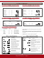
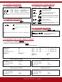
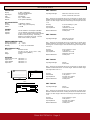
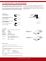
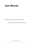
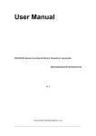
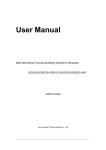
User’s Manual TAS-VAC, VDC, IAC and IDC
Connections .Cables A and B as
Standard Modbus
Terminator .- Place jumper if the BUS
ends on this instrument
Terminal 14 - B
Terminal 13 - A
7.3.1 MODBUS STRUCTURE
Example for a Modbus-RTU frame .- Start Character corresponds with instrument address and final character
corresponds with the CRC Security Code
In Modbus-ASCII Start and End characters are specific
T1 = Time between two characters
T2 = Time between end of question and start of response
T3 = Time between end of response and start of next question
T2 MAX
(RTU and ASCII)
38400
19200
9600
4800
2400
4.3 msec
5.7 msec
9.2 msec
15.5 msec
27 msec
T1 (min/max)
RTU ASCII
0CT / 3CT
0CT / ---
Character Structure
Bit structure for the characters on protocols ModBus RTU and ModBus
ASCII
START
DATA
PARITY STOP
TOTAL BITS
RTU
1
1
1
8
8
8
P
I
--
1
1
2
11
11
11
ASCII
1
1
1
7
7
7
P
I
--
1
1
2
10
10
10
Frame Structure
QUESTION : Communication MASTER and SLAVE
ADDRESS
FUNCTION
READING START REGISTER NUMBER OF REGISTERS TO READ
CRC
1 CHARACTER
1 CHARACTER
2 CHARACTERS
X CHARACTERS
2 CHARACTERS
Instrument Address
Function 04H, register read
Register 00 00H = Display Value
02 = 2 registers (4 bytes)
Control Checksum
1 CHARACTER
1 CHARACTER
1 CHARACTER
X CHARACTERS
2 CHARACTERS
Instrument Address
Function 04H, register read
Number of data characters following
Response data*
Control Checksum
RESPONSE : Communication SLAVE to MASTER
ADDRESS
FUNCTION
LENGTH
DATA
CRC
FEMA ELECTRÓNICA - Page 13
T3 (min/max)
RTU ASCII
3.5CT / ---- / ---