1
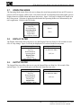
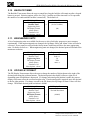
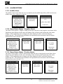
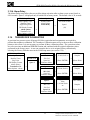
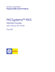
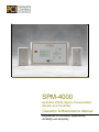
SPM-4000
Guardian Infinity Space Pressurization
Monitor and Controller
Operation & Maintenance Manual
Engineered for accuracy, applicability,
durability and simplicity
SPM-4000 Guardian Infinity Operation & Maintenance Manual
TABLE OF CONTENTS
TABLE OF CONTENTS............................................................................................................................. i
1. INTRODUCTION .............................................................................................................................. 1
1.1. BASIC OPERATION ................................................................................................................. 1
1.2.
SAFETY ..................................................................................................................................... 1
1.2.1.
Electrical Connections ........................................................................................................ 1
1.2.2.
Static Electricity.................................................................................................................. 1
2. HARDWARE CONFIGURATION.................................................................................................... 2
2.1. GUARDIAN INFINITY COMPONENT LAYOUT.................................................................. 2
2.1.1.
Front Component Layout.................................................................................................... 2
2.1.2.
Back Component and Connector Layout............................................................................ 3
2.2. HARDWARE SPECIFICATIONS OF INPUTS AND OUTPUTS........................................... 4
2.2.1.
Power Input......................................................................................................................... 4
2.2.2.
Pressure Sensor Inputs ........................................................................................................ 4
2.2.3.
Analog Inputs...................................................................................................................... 4
2.2.4.
Analog Outputs ................................................................................................................... 4
2.2.5.
Remote Space Pressure Alarm relay................................................................................... 4
2.2.6.
Remote Operating Mode Select Switch.............................................................................. 4
2.2.7.
RPM Output ........................................................................................................................ 4
2.2.8.
Lonworks / Bacnet Output .................................................................................................. 4
2.2.9.
System Start ........................................................................................................................ 4
2.2.10. Door Interlock..................................................................................................................... 5
2.2.11. IrDA Port ............................................................................................................................ 5
2.2.12. LCD..................................................................................................................................... 5
2.2.13. Buzzer ................................................................................................................................. 5
2.2.14. LED’s.................................................................................................................................. 6
2.2.15. Buttons & Switches............................................................................................................. 6
3. DISPLAY MENUS............................................................................................................................. 8
3.1.
POWER UP DISPLAY............................................................................................................... 8
3.2.
SYSTEM DATA MENU............................................................................................................ 8
3.3.
FIELD SETUP & INITIAL PASSWORD MENU..................................................................... 8
3.4. OPERATING RANGE ............................................................................................................... 9
3.5. ZERO CALIBRATION .............................................................................................................. 9
3.6.
ROOM IDENTIFIERS ............................................................................................................... 9
3.7. OPERATING MODE ............................................................................................................... 10
3.8. DISPLAY FILTER ................................................................................................................... 10
3.9. OUTPUT FILTER .................................................................................................................... 10
3.10.
BACKLITE TIMER ............................................................................................................. 11
3.11.
ENGINEERING UNITS....................................................................................................... 11
3.12.
DP DISPLAY FORMAT...................................................................................................... 11
3.13.
ALARM OPTIONS .............................................................................................................. 12
3.13.1. Audible Alarm .................................................................................................................. 12
3.13.2. Alarm Values (Space 1 Negative Alarm) ......................................................................... 12
3.13.3. Alarm Values (Space 1 Positive Alarm)........................................................................... 12
3.13.4. Alarm Delay...................................................................................................................... 13
3.14.
TRANSDUCER CALIBRATION........................................................................................ 13
3.15.
OUTPUT CALIBRATION................................................................................................... 14
3.16.
OUTPUT SELECTION ........................................................................................................ 14
3.17.
CONTROL TUNING AND SETTINGS.............................................................................. 15
i
Paragon Controls Incorporated, Rev V1.6,7/30/09
Phone 707 / 579-1424, Fax 707 / 579-8480
SPM-4000 Guardian Infinity Operation & Maintenance Manual
3.17.1. Tuning Parameters ............................................................................................................ 15
3.17.2. Action................................................................................................................................ 15
3.17.3. Door Interlock................................................................................................................... 15
3.17.4. Setpoint Internal/External ................................................................................................. 16
3.17.5. Controller Setpoint Values................................................................................................ 16
3.17.6. Output Start....................................................................................................................... 16
3.17.7. Alarms ON/OFF................................................................................................................ 17
3.17.8. Output Override ................................................................................................................ 17
3.17.9. System Alarm Delay ......................................................................................................... 17
3.18.
TEMPERATURE OPTIONS................................................................................................ 18
3.18.1. Temperature Display OFF/ON ......................................................................................... 18
3.18.2. Temperature Units ............................................................................................................ 18
3.18.3. Temperature Range........................................................................................................... 18
3.18.4. Temperature Alarm ON/OFF............................................................................................ 19
3.18.5. Temperature Alarm Values............................................................................................... 19
3.18.6. LonWorks Temperature .................................................................................................... 19
3.19.
HUMIDITY OPTIONS ........................................................................................................ 20
3.19.1. Humidity Display ON/OFF............................................................................................... 20
3.19.2. Humidity Alarm ON / OFF............................................................................................... 20
3.19.3. Humidity Alarm Values.................................................................................................... 20
3.19.4. LonWorks RH................................................................................................................... 21
3.20.
FLOW AND ACH OPTIONS .............................................................................................. 21
3.20.1. Flow/ACH Display ON/OFF ............................................................................................ 21
3.20.2. Flow Range ....................................................................................................................... 21
3.20.3. Room Volume................................................................................................................... 22
3.20.4. Flow Alarm ON/OFF........................................................................................................ 22
3.20.5. Flow Alarm Values ........................................................................................................... 22
3.20.6. ACH Alarm ON/OFF........................................................................................................ 22
3.20.7. ACH Alarm Value ............................................................................................................ 23
3.20.8. LonWorks Flow/ACH....................................................................................................... 23
3.21.
MAC ADDRESS .................................................................................................................. 23
3.22.
INSTANCE NUMBER......................................................................................................... 24
3.23.
PASSWORD TIMEOUT...................................................................................................... 24
3.24.
FIELD PASSWORD ............................................................................................................ 24
3.25.
FACTORY PASSWORD ..................................................................................................... 25
3.26.
FACTORY DEFAULTS ...................................................................................................... 25
4. TROUBLESHOOTING GUIDE ...................................................................................................... 26
ii
Paragon Controls Incorporated, Rev V1.6,7/30/09
Phone 707 / 579-1424, Fax 707 / 579-8480
SPM-4000 Guardian Infinity Operation & Maintenance Manual
1. INTRODUCTION
This user manual provides information on product features and guides you through all basic
functionality.
1.1.
BASIC OPERATION
The Guardian Infinity is a true differential space pressure measurement system engineered to combine
the operability of today’s microprocessor technology with state-of-the-art, industrial grade, highly
accurate, ultra low range, differential pressure sensing cells. The combination of these two technologies
ensures exceptional long-term stability and ±0.25% measurement accuracy.
Field configuration of engineering units, operating mode, operating range, process noise filtering, alarm
set points, etc, are performed via password protected intuitive menus that are accessed through the
integral six button touch pad. Device monitoring and configuration can also be performed by a building
management system through either a LonWorks® or BACnet®-MS/TP communication network as well
as through a local IR communication port using a laptop or handheld PDA. An additional network
communication port is available for connection to a Paragon remote pressure monitor. The front panel
includes an 8 line graphic display for local indication of the space pressure and device configuration,
LED indication of operational mode and status, and an audible alarm with alarm acknowledge button.
The Guardian Infinity offers an optional controller that utilizes a proprietary algorithm which results in
true three mode control incorporating proportional band, integral (reset) and inverse derivative (P, I,
1/D) controller functionality and tuning. The controller will provide responsive modulation of a control
damper or variable speed drive ensuring a stable space pressure is maintained.
1.2.
SAFETY
1.2.1. Electrical Connections
Before any electrical connections are made, ensure the POWER SWITCH is in the OFF position.
1.2.2. Static Electricity
The circuit board contains components which are susceptible to damage caused by static electrical
discharge. Should it be necessary to remove the circuit board from the enclosure, appropriate
precautions must first be taken to ensure that the operator and the circuit board are at the same electrical
potential.
1
Paragon Controls Incorporated, Rev.V1.6, 7/30/09
Phone 707 / 579-1424, Fax 707 / 579-8480
SPM-4000 Guardian Infinity Operation & Maintenance Manual
2. HARDWARE CONFIGURATION
The Guardian Infinity consists of the pressure measurement circuits, digital input/outputs, analog
inputs/outputs (Voltage/Current), BACnet / LonWorks and IrDA communication and Graphical LCD
unit in a single board.
2.1.
GUARDIAN INFINITY COMPONENT LAYOUT
2.1.1. Front Component Layout
Refer to Figure 2.0 for clarification on the front component layout.
DISPLAY
TEXT INTENSITY
SPACE 1
NORMAL
ROOM
AUDIBLE
ALARM
ALARM
REF
SPARE
S10 ON
BACNET
TERMINATOR
UP
LEFT
LCD GRAPHICS DISPLAY
RIGHT
DOWN
SPACE 2
ROOM
MENU
ENTER
ACK
ESC
REF
7
20
1
1
ON
ON
S1
S9
ON
SP1
SP2
OUTPUT OUTPUT
JP1
JP2
I
V
V
I
V
SP1 / SP2 / CONTROLLER
OUTPUT SELECTION
POWER SWITCH
EXAMPLE: CURRENT
VOLTAGE/CURRENT INPUT SELECTION
SWITCH S1 SWITCH S9
INPUT
1
1
CONTROLLER SETPOINT
TEMPERATURE
2
2
RH
3
3
CFM
4
4
5
5
AUX.
I
CONTROLLER
OUTPUT
JP3
I/V SELECTION
OFF = V / ON = I
OFF = V / ON = I
OFF = V / ON = I
OFF = V / ON = I
OFF = V / ON = I
VOLTAGE
FIGURE 2.0
2
Paragon Controls Incorporated, Rev.V1.6, 7/30/09
Phone 707 / 579-1424, Fax 707 / 579-8480
SPM-4000 Guardian Infinity Operation & Maintenance Manual
2.1.2. Back Component and Connector Layout
Refer to Figure 2.1 for clarification on the back component and connector layout.
ID LABEL
GUARD PLATE
CONNECTOR LABEL
ROOM PRESSURE
CONNECTION
(CLEAR TUBING)
REFERENCE PRESSURE
CONNECTION
(BLACK TUBING)
SPACE 1
TRANSDUCER
38 37
J4 J3
40 39
ROOM PRESSURE
CONNECTION
(CLEAR TUBING)
REFERENCE PRESSURE
CONNECTION
(BLACK TUBING)
SPACE 2
TRANSDUCER
J6
36 35 34 33 32 31 30 29 28 27 26
J5
J1
J2
25 24 23 22 21 20 19 18 17 16
15 14 13 12 11 10
9
8
7
6
5
4
J3
J1
3
2
1
J6
+
CONNECTION TO RPM
24VAC (50/60HZ)
SYSTEM START
EARTH GROUND
DOOR INTERLOCK
J4
+ CONTROLLER SETPOINT INPUT
+
LONWORKS / BACNET COMMUNICATIONS
- CONTROLLER SETPOINT INPUT
-
J2
+ CONTROLLER OUTPUT
+ TEMP. INPUT
- TEMP. INPUT
- CONTROLLER OUTPUT
J5
COM
+ RH INPUT
+ SP 1 PROCESS OUTPUT
- RH INPUT
- SP 1 PROCESS OUTPUT
NO
AUX. RELAY
NC
+ CFM INPUT
+ SP 2 PROCESS OUTPUT
- CFM INPUT
- SP 2 PROCESS OUTPUT
+ AUX. INPUT
POSITIVE ROOM SEL.
- AUX. INPUT
NEGATIVE ROOM SEL.
+15VDC
+15VDC
3 POSITION
POS/NEG/OFF
ROOM SELECT
SWITCH
GROUND
LOOP POWER
COM
NO
SPACE PRESSURE ALARM
AUX. DI
NC
FIGURE 2.1
3
Paragon Controls Incorporated, Rev.V1.6, 7/30/09
Phone 707 / 579-1424, Fax 707 / 579-8480
SPM-4000 Guardian Infinity Operation & Maintenance Manual
2.2.
HARDWARE SPECIFICATIONS OF INPUTS AND OUTPUTS
2.2.1. Power Input
The power input requirement is 20-28VAC at 50-60Hz. Line power is connected to input socket (J1).
The unit has an isolated DC-DC converter, which creates electrical isolation between the power input
and the unit.
2.2.2. Pressure Sensor Inputs
The SPM-4000 is factory configured for bi-directional or uni-directional pressure inputs. Bi-directional
pressure input provides both positive and negative pressure values. Uni-directional pressure input
provides only positive pressure values.
2.2.3. Analog Inputs
The Guardian Infinity supports five analog inputs; controller set point input, temperature sensor input,
humidity sensor input, flow sensor input, and auxiliary analog input. Slide switches S1 and S9 are used
for voltage/current input selection. For details, see Section 2.2.10.
2.2.4. Analog Outputs
The Guardian Infinity provides three channels 4-20mA or 0-10VDC analog outputs. Jumpers JP1, JP2
and JP3 are used in conjunction with the menu for voltage/current output selection. The maximum
output load impedance for current output is 500 ohms. The minimum load impedance for voltage output
is 1000 ohms.
2.2.5. Remote Space Pressure Alarm relay
The contact rating of the SPDT alarm relay is 0.6A at 125VAC or 110VDC and 2.0A at 30VDC.
2.2.6. Remote Operating Mode Select Switch
Connecting a single pole 3 position switch to pins 20, 21 & 22 of (J5) connector allows the user to
remotely change SP1 and SP2 operating mode to Positive, Negative or Off. To activate the remote
operating mode select input, the user must enter the Operating Mode menu and select the OFF mode
(see section 3.7).
2.2.7. RPM Output
Pins 37-38 of (J3) are used to connect to a Paragon Remote Pressure Monitor (RPM).
2.2.8. Lonworks / Bacnet Output
Pins 39-40 of (J4) are used to connect to a LonWorks® or BACnet®-MS/TP communication network.
The output requires an optional LonWorks or BACnet daughter board to be installed into the main
board.
2.2.9. System Start
Pins 26-27 of (J6) are used to indicate that a fan system is enabled and to activate the internal control
algorithm.
4
Paragon Controls Incorporated, Rev.V1.6, 7/30/09
Phone 707 / 579-1424, Fax 707 / 579-8480
SPM-4000 Guardian Infinity Operation & Maintenance Manual
2.2.10. Door Interlock
Pins 28-29 of (J6) are used to interface with a door interlock switch that when activated causes the
controller output to either lock at that position or offset by a predetermined percentage.
2.2.11. IrDA Port
The Guardian Infinity provides IrDA communication with a handheld PDA or PC software
MGUSim V2xx. For proper communication, the IrDA instrument must be aligned with the unit IrDA
window and the maximum distance must be kept to 1 foot or less.
2.2.12. LCD
A 128x64 graphical LCD displays pressure, engineering units, and menus. The decimal point and
polarity will be selected automatically based on the engineering unit and range selection.
ROOM 1204
0.0000
*
Inch w.c.
ROOM 1204
0.0000
*
ROOM 1204
Inch w.c.
*
0.0000 Inch w.c.
ROOM 1205
10,000 CFM
75 º F
10 ACH
55 %RH
Single Room display with
optional CFM,ACH,
Temperature & RH
0.0000
Inch w.c.
Dual Room Display
10,000 CFM
10 ACH
75 ˚ F
55 %RH
DOOR
50%
RUN
Single Room Display with
CFM,ACH, Temperature,
RH & Controller status
2.2.13. Buzzer
A 85dB (max), 40mA buzzer is used for providing an audible alarm. The audible alarm has two sound
options, continuous and interval. The buzzer sound options and alarm ON/OFF option are selected
through the Audible Alarm menu (see section 13.3).
5
Paragon Controls Incorporated, Rev.V1.6, 7/30/09
Phone 707 / 579-1424, Fax 707 / 579-8480
SPM-4000 Guardian Infinity Operation & Maintenance Manual
2.2.14. LED’s
The Guardian Infinity unit has two surface mount LED's and two solid state LED’s (Light Emitting
diodes). LED functions are shown below:
Note: ACK refers to the alarm acknowledge keypad button.
2.2.14.1.
Normal Status LED (DL3)
LED State
On
Off
Blink
2.2.14.2.
Operation State
Alarm goes off and ACK ok.
Alarm state
Alarm goes off with no ACK
Alarm Status LED(DL4)
LED State
On
Off
Blink
2.2.14.3.
Operation State
Alarm state and ACK ok.
No Alarm state
Alarm state but no ACK
Surface Mount LED’s(DL1-2)
LED State
On
Off
Blink
Status LED(DL1)
IrDA Comm.
Established
No IrDA Comm.
-
Diag. LED(DL2)
BACnet Data Sending
2.2.15. Buttons & Switches
The Guardian Infinity unit has a 6 button keypad. The Unit also has 4 switches and 3 jumpers. Buttons
are used for menu navigation, data entering and alarm acknowledge. The functions are shown below:
2.2.15.1.
Button Functions
Button
UP
DOWN
LEFT
RIGHT
MENU/ENTER
ESC/ACK
2.2.15.2.
Button Function
Menu Browser/Parameter Setting
Menu Browser/ Parameter Setting
Parameter Setting
Parameter Setting
Menu Browser/ Parameter Setting
Menu Browser/AlarmAcknowledge
Switch Functions
Switch
S2 (Slide switch)
S1.1 (Dip switch)
S1.2 (Dip switch)
Function
Unit Power On/Off
BACnet Rs-485 Termination On/Off
Not Used
6
Paragon Controls Incorporated, Rev.V1.6, 7/30/09
Phone 707 / 579-1424, Fax 707 / 579-8480
SPM-4000 Guardian Infinity Operation & Maintenance Manual
2.2.15.3.
Analog Input Select Switch Functions
Analog Input
Controller Setpoint Analog Input
Temperature Analog Input
Humidity Analog Input
Flow Analog Input
Auxiliary Analog Input
2.2.15.4.
Switch Pos.
S1-1 and S9-1 On: 4-20 mA
S1-2 and S9-2 On: 4-20 mA
S1-3 and S9-3 On: 4-20 mA
S1-4 and S9-4 On: 4-20 mA
S1-5 and S9-5 On: 4-20 mA
S1-1 and S9-1 Off: 0-10V
S1-2 and S9-2 Off: 0-10V
S1-3 and S9-3 Off: 0-10V
S1-4 and S9-4 Off: 0-10V
S1-5 and S9-5 Off: 0-10V
Jumper Functions (See Figure 2.0)
Jumper
JP1 (Space1 Analog Output)
JP2 (Space2 Analog Output)
JP3 (Controller Analog Output)
Function
Jumper 1-2 Pos: 4-20mA, Jumper 2-3 Pos:0-10V
Jumper 1-2 Pos: 4-20mA, Jumper 2-3 Pos:0-10V
Jumper 1-2 Pos: 4-20mA, Jumper 2-3 Pos:0-10V
Caution: Making output current/voltage changes requires selecting the correct JP1, JP2 or JP3
position and making the same current /voltage selection in the Output Selection menu (See
example in Section 3.16).
7
Paragon Controls Incorporated, Rev.V1.6, 7/30/09
Phone 707 / 579-1424, Fax 707 / 579-8480
SPM-4000 Guardian Infinity Operation & Maintenance Manual
3. DISPLAY MENUS
3.1.
POWER UP DISPLAY
The Power Up menu displays the product name, software revision installed, work order number and
optional BACnet revision.
Guardian Infinity
Software Rev. 60.xxx
W.O. Number xxxxx
Bacnet Rev. 10.xxx
3.2.
SYSTEM DATA MENU
The System Data menu includes alarm values, operating modes and set point values. The alarm values
shown will be determined by the operating mode selected. If positive mode is selected, the display will
show only the positive alarm and set point values. If negative mode is selected, the display will show
only the negative alarm and set point values.
To display the System Data menu, depress and hold the ENTER button for three seconds.
System Data
SP1 Mode
Pos.
SP1 Low
+.005
SP1 High
+0.49
SP2 Mode
Pos.
SP2 Low
+.003
SP2 High
+.045
More Selections <down>
3.3.
FIELD SETUP & INITIAL PASSWORD MENU
To enter the Field Setup menu from the process display, the user will need to depress the UP/DOWN
buttons simultaneously. The Field Setup Password menu will appear. The initial password shipped
from the factory is 00000.
Field Setup
Password
(00000)
8
Paragon Controls Incorporated, Rev.V1.6, 7/30/09
Phone 707 / 579-1424, Fax 707 / 579-8480
SPM-4000 Guardian Infinity Operation & Maintenance Manual
3.4.
OPERATING RANGE
The Operating Range value is the pressure range that correlates with the 0 to 10vdc or 4 to 20mA output
signal. The allowable Operating Range value is from 40 to 100% of the Max. F.S. Value shown on the
display. If an invalid value is entered, the display will change to an error message and the value will not
be accepted.
Field Setup Menu
Space 1 Op. Range
Operating Range
Zero Cal
Room Identifiers
Operating Mode
Display Filter
Output Filter
More Options <down>
3.5.
→
(Inch w.c.)
Max. F.S. Value
(0.1000)
Operating Range
(0.1000)
ZERO CALIBRATION
Zero Calibration allows the user to easily correct for any zero transducer shift. Any error found will be
added to the value created during the factory calibration procedure. This correction value will be stored
in an additional EPROM location in case the user needs to return the device to the original factory
calibration. This can be done by entering the Factory Defaults menu (see Section 3.26). If a Zero
Calibration is performed which exceeds factory limits, an error message stating this will appear and the
reading will not be accepted.
Field Setup Menu
Operating Range
Zero Cal
Room Identifiers
Operating Mode
Display Filter
Output Filter
More Options <down>
3.6.
Zero Cal
→
Zero Cal. Space 1
→
Space 1
Input Zero Value
(0.000 Pressure)
CPU Taking
Samples
→
(Press Enter)
(Please Wait)
ROOM IDENTIFIERS
The Room Identifiers menu allows the user to enter upper case alpha and numeric characters to identify
Space 1 or optional Space 2 on the display. The user will be able to enter 16 characters. One character
at a time will be entered, starting with the far left character.
Field Setup Menu
Operating Range
Zero Cal
Room Identifiers
Operating Mode
Display Filter
Output Filter
More Options <down>
Room Identifier
Space 1
Identifier
→
(ROOM 205)
Press Enter
9
Paragon Controls Incorporated, Rev.V1.6, 7/30/09
Phone 707 / 579-1424, Fax 707 / 579-8480
SPM-4000 Guardian Infinity Operation & Maintenance Manual
3.7.
OPERATING MODE
The Operating Mode menu allows the user to change the room being monitored from an OFF room to a
positive (POS) or negative (NEG) room. Selection of an OFF room disables alarm status lights, process
display alarm text, audible alarm and remote alarm relay. Space 2 will only be displayed if turned on in
the Factory menu. Selection of options described under the Operating Mode text is determined by the
unit’s application. Default is the POS mode.
Field Setup Menu
Operating Range
Zero Cal
Room Identifiers
Operating Mode
Display Filter
Output Filter
More Options <down>
3.8.
Operating Mode
(OFF/POS/NEG)
Space 1
→
(Pos)
DISPLAY FILTER
The Display Filter menu allows the user to vary the Display Filter rate from 0 to 100 seconds to reach
98% of a step change. Space 2 will only be displayed if it is selected in the Factory menu.
Field Setup Menu
Operating Range
Zero Cal
Room Identifiers
Operating Mode
Display Filter
Output Filter
More Options <down>
3.9.
Space 1 Filter
(0=Min./100=Max.)
(003) sec.
→
OUTPUT FILTER
The Output Filter menu allows the user to vary the Output Filter rate from 0 to 100 seconds. If the
optional Space 2 is selected, both spaces will have the same filter rate value.
Field Setup Menu
Operating Range
Zero Cal
Room Identifiers
Operating Mode
Display Filter
Output Filter
More Options <down>
Output Filter
(0=Min./100=Max.)
(003) sec.
→
10
Paragon Controls Incorporated, Rev.V1.6, 7/30/09
Phone 707 / 579-1424, Fax 707 / 579-8480
SPM-4000 Guardian Infinity Operation & Maintenance Manual
3.10. BACKLITE TIMER
The Backlite Timer menu allows the user to control how long the backlite will remain on after a keypad
button is pressed. Selection options will be 0 to 30 (0 = backlite on all the time and 1 to 30 represents
the number of seconds until the backlite is turned off). The default is 0.
Field Setup Menu
More Options <up>
Backlite Timer
Engineering Units
DP Display Format
Alarm options
Transducer Cal.
More Options <down>
Backlite Timer
→
(0=On /30=Max.)
(00)
3.11. ENGINEERING UNITS
A list of engineering units are available for the user to select for display purposes to meet customer
requirements. If the engineering units are changed, the Op Range values and Alarm Values will also be
corrected. If two rooms are selected in the factory menu, both rooms will have the same engineering
units. Default to be Inch w.c. When engineering units are changed, the decimal point will default to the
maximum resolution.
Field Setup Menu
More Options <up>
Backlite Timer
Engineering Units
DP Display Format
Alarm options
Transducer Cal.
More Options <down>
Engineering Units
→
Inch w.c.
Pa
KPa
mm w.c.
3.12. DP DISPLAY FORMAT
The DP Display Format menu allows the user to change the number of digits shown to the right of the
decimal point using the up/down buttons. The decimal point in the display will move right or left
depending upon which button is depressed. If a change in decimal point position is made, the process
display value must reflect the corrected weight value. If no decimal point is required, move the decimal
to the far right position. If a change is made to the DP format, the Op Range & Alarm Values will also
change. The default decimal point resolution is 0.0000.
Field Setup Menu
More Options <up>
Backlite Timer
Engineering Units
DP Display Format
Alarm options
Transducer Cal.
More Options <down>
DP Display Format
Decimal Resolution
→
11
(0.0000)
Paragon Controls Incorporated, Rev.V1.6, 7/30/09
Phone 707 / 579-1424, Fax 707 / 579-8480
SPM-4000 Guardian Infinity Operation & Maintenance Manual
3.13. ALARM OPTIONS
3.13.1. Audible Alarm
The Audible Alarm menu allows the user to manually turn the audible alarm ON or OFF and select the
audible alarm to be continuous or interval.
Field Setup Menu
More Options <up>
Backlite Timer
Engineering Units
DP Display Format
Alarm options
Transducer Cal.
More Options <down>
Alarm Options
Audible Alarm
Alarm Values
Alarm Delay
Audible Alarm
(On/Off)
(On)
→
Audible Alarm Mode
→
(Continuous)
3.13.2. Alarm Values (Space 1 Negative Alarm)
The Alarm Values (Space 1 Negative Alarm) menu allows the user to enter negative room alarm values.
Engineering units displayed in the menu will change if the selection in the Engineering Units menu
changes. If the engineering unit is changed, the values displayed will be converted to the new
engineering unit. The decimal point resolution will represent the selection made in the DP Display
Format menu (refer to Section 3.12).
Field Setup Menu
More Options <up>
Backlite Timer
Engineering Units
DP Display Format
Alarm options
Transducer Cal.
More Options <down>
Alarm Options
Audible Alarm
Alarm Values
Alarm Delay
Alarm Values
→
Space 1 Negative
(Inch w.c.)
→
Space 1 Neg.
Space 1 Pos.
Low Alarm
(+0.0000)
→
High Alarm
(-0.1000)
3.13.3. Alarm Values (Space 1 Positive Alarm)
The Alarm Values (Space 1 Postive Alarm) menu allows the user to enter positive room alarm values.
Engineering units displayed in the menu will change if the selection in the Engineering Units menu
changes. If the engineering unit is changed, the values displayed will be converted to the new
engineering unit. The decimal point resolution will represent the selection made in the DP Display
Format menu (refer to Section 3.12).
Field Setup Menu
More Options <up>
Backlite Timer
Engineering Units
DP Display Format
Alarm Options
Transducer Cal.
More Options <down>
Alarm Options
Audible Alarm
Alarm Values
Alarm Delay
Alarm Values
→
Space 1 Neg.
Space 1 Pos.
Space 1 Positive
(Inch w.c.)
→
Low Alarm
(+0.0000)
→
High Alarm
(+0.1000)
12
Paragon Controls Incorporated, Rev.V1.6, 7/30/09
Phone 707 / 579-1424, Fax 707 / 579-8480
SPM-4000 Guardian Infinity Operation & Maintenance Manual
3.13.4. Alarm Delay
The Alarm Delay menu allows the user to delay alarm activation after an alarm event occurs from 0 to
9999 seconds. Space 2 is displayed only if turned ON in factory menu. The default value is 30 seconds.
Field Setup Menu
More Options <up>
Backlite Timer
Engineering Units
DP Display Format
Alarm options
Transducer Cal.
More Options <down>
3.14.
Alarm Options
Audible Alarm
Alarm Values
Alarm Delay
Alarm Delay
0 to 9999 seconds
→
Space 1
(30)
→
TRANSDUCER CALIBRATION
A precision low pressure source (Paragon PS-100 or equivalent and a manometer are required to
perform the transducer calibration. The Transducer Calibration menu will give the user three calibration
points to select from. It is not necessary to perform all three calibration points. The correction values
are to be store into an additional EPROM location and combined with the original calibration values
performed in the factory menu. A user can return the device to its original factory calibration by
selecting the Factory Defaults menu in the Field Setup menu (see section 3.26).
Field Setup Menu
More Options <up>
Backlite Timer
Eng. Units
DP Display Format
Alarm options
Transducer Cal.
More Options <down>
Trans. Cal.
Space 1
→
→
Space 1
Min. Cal.
50% Cal.
Span Cal.
Return to Menu
Input Min. Value
→ (-0.1000) Inch wc
(Press ENTER)
(Please Wait)
Space 1
Min. Cal.
50% Cal.
Span Cal.
Return to Menu
Input 50% Value
(0.0000) Inch wc
CPU Taking
Samples
→
→
Input 100%
Value
(+0.1000) Inch
wc
Min. Cal.
13
→
(Press ENTER)
Space 1
50% Cal.
Span Cal.
Return to Menu
CPU Taking
Samples
→
(Press ENTER)
(Please Wait)
CPU Taking
Samples
(Please Wait)
Paragon Controls Incorporated, Rev.V1.6, 7/30/09
Phone 707 / 579-1424, Fax 707 / 579-8480
SPM-4000 Guardian Infinity Operation & Maintenance Manual
3.15. OUTPUT CALIBRATION
The Output Calibration menu allows the user to make corrections to the minimum and maximum
Process and Controller Output Values (refer to Section 2.1.2). By applying minimum and maximum
input pressures, Zero and Span Process Output Values can be set to the output limits. Use the
UP/DOWN buttons to make any correction necessary. By pressing the Enter button, these correction
values are stored in the EPROM. Use the same correction procedure to set the minimum and maximum
Controller output limits.
Field Setup Menu
More Options <up>
Output Cal.
Output Selection
Control Settings
Temp. Options
Humidity
More Options <down>
Output Cal.
→
Sp 1 Output Cal.
Sp 2 Output Cal.
Cont. Output Cal.
→
→
Sp1 Output
Sp1 Volt Zero
Sp1 Volt Span
Sp1 Cur. Zero
Sp1 Cur. Span
Sp1 Output
Sp1 Volt Zero
Sp1 Volt Span
Sp1 Cur. Zero
Sp1 Cur. Span
→
→
Output Calibration
Monitor output
Press Up/Down
Buttons until
Output is 0.000
(Press Enter)
Output Calibration
Monitor output
Press Up/Down
Buttons until
Output is 10.000
(Press Enter)
3.16. OUTPUT SELECTION
The Output Selection menu allows the user to make Current (I)/Voltage (V) output changes to Space 1,
Space 2 and Controller outputs. Along with a menu change, repositioning of jumpers JP1, JP2 and JP3
is required (Refer to Section 2.1.1). The following example is shown for Space 1; Space 2 and
Controller Output Selection are performed the same.
Field Setup Menu
More Options <up>
Output Cal.
Output Selection
Control Settings
Temp. Options
Humidity
More Options <down>
→
Output Selection
Sp1 Output Sel.
Sp2 Output Sel.
Cont. Output Sel.
SP1 Output Select
→
SP1 Output
Current/Voltage
(I)
14
Paragon Controls Incorporated, Rev.V1.6, 7/30/09
Phone 707 / 579-1424, Fax 707 / 579-8480
SPM-4000 Guardian Infinity Operation & Maintenance Manual
3.17. CONTROL TUNING AND SETTINGS
The Controller menus will only be displayed on units with the controller option purchased.
3.17.1. Tuning Parameters
The Tuning Parameters menu allows the user to tune the controller parameters to match the system
dynamics. The Proportional Band value can be entered as a percent value from 1 to 100%. Reset and
Inverse Derivative values will range from 0 to 300 seconds. Default values will be Proportional Band =
10%, Reset (Integrator Tim) = 70 seconds and Inverse Derivative = 60 seconds.
Field Setup Menu
More Options <up>
Output Cal.
Output Selection
Control Settings
Temp. Options
Humidity
More Options <down>
Control Settings
Tuning Parameter
Action
Door Interlock
Setpoint Int/Ext
Cont. Setpoints
Output Start
More Options <down>
→
Tuning Parameters
Proportional Band
(0010)%
Integrator Tim
(070) sec.
1/Derivative
(060) sec.
→
3.17.2. Action
The Action menu allows the user to select between Direct and Reverse action. The default is Reverse
action.
Field Setup Menu
More Options <up>
Output Cal.
Output Selection
Control Settings
Temp. Options
Humidity
More Options <down>
→
Control Settings
Tuning Parameter
Action
Door Interlock
Setpoint Int/Ext
Cont. Setpoints
Output Start
More Options <down>
Action
Direct/Reverse
→
(Reverse)
3.17.3. Door Interlock
The Door Interlock menu allows the user to select between two output options when the door interlock
input is activated. The Lock function will lock the output at the value it was when the door interlock
input was activated. When the door interlock input is de-activated, the output resumes automatic
modulation to balance the process to the setpoint value. The % Change function will add or subtract a
percent of full scale output to the output value when the door interlock input is activated. When the door
interlock input is deactivated the output will immediately go to the previous output value and resume
automatic modulation to balance the process to the setpoint value. The default value is 000%.
Field Setup Menu
More Options <up>
Output Cal.
Output Selection
Control Settings
Temp. Options
Humidity
More Options <down>
→
Control Settings
Tuning Parameter
Action
Door Interlock
Setpoint Int/Ext
Cont. Setpoints
Output Start
More Options <down>
15
Door Interlock
Lock / % Change
→
(Lock)
% Change ±100
(+50)
Paragon Controls Incorporated, Rev.V1.6, 7/30/09
Phone 707 / 579-1424, Fax 707 / 579-8480
SPM-4000 Guardian Infinity Operation & Maintenance Manual
3.17.4. Setpoint Internal/External
The Setpoint menu allows the user to select between internal (INT) setpoint (entered by the menu or
through the network) or remote external (EXT) setpoint. The default is INT.
Field Setup Menu
More Options <up>
Output Cal.
Output Selection
Control Settings
Temp. Options
Humidity
More Options <down>
→
Control Settings
Tuning Parameter
Action
Door Interlock
Setpoint Int/Ext
Cont. Setpoints
Output Start
More Options <down>
Setpoint
INT/EXT
(INT)
→
3.17.5. Controller Setpoint Values
The Controller Setpoints menu allows the user to enter Positive, Negative and Off setpoint values. The
default values is 0.0000. If values entered are outside of acceptable range, an error message will indicate
the acceptable range.
Field Setup Menu
More Options <up>
Output Cal.
Output Selection
Control Settings
Temp. Options
Humidity
More Options <down>
→
Control Settings
Tuning Parameter
Action
Door Interlock
Setpoint Int/Ext
Cont. Setpoints
Output Start
More Options <down>
→
Cont. Setpoints
Pos.
( 0.0000)
Neg.
(0.0000)
Off
(0.0000)
3.17.6. Output Start
The Output Start menu allows the user to select the output condition when the System Start input is not
active. If Min. is selected, the output will start at 0vdc (4ma) and modulate from there. If Max. is
selected, the output will start at 10vdc (20ma) and modulate from there. The default is MIN.
Field Setup Menu
More Options <up>
Output Cal.
Output Selection
Control Settings
Temp. Options
Humidity
More Options <down>
→
Control Settings
Tuning Parameter
Action
Door Interlock
Setpoint Int/Ext
Cont. Setpoints
Output Start
More Options <down>
16
System OFF
Output Value
Min./Max.
(MIN)
→
Paragon Controls Incorporated, Rev.V1.6, 7/30/09
Phone 707 / 579-1424, Fax 707 / 579-8480
SPM-4000 Guardian Infinity Operation & Maintenance Manual
3.17.7. Alarms ON/OFF
The Alarms ON/OFF menu allows user to determine if all alarms will be active (ON) or inactive (OFF)
when the System Start input is de-activated. The default is OFF.
Field Setup Menu
More Options <up>
Output Cal.
Output Selection
Control Settings
Temp. Options
Humidity
More Options <down>
→
Control Settings
More Options <up>
Alarm ON/OFF
Output Override
Sys. Alarm Delay
System Start
→
De-activated
All Alarm Status
(ON/OFF)
(OFF)
3.17.8. Output Override
The Output Override menu allows the user to manually set the controller output to a fixed value. The
defaults are OFF and 50%.
Field Setup Menu
More Options <up>
Output Cal.
Output Selection
Control Settings
Temp. Options
Humidity
More Options <down>
→
Control Settings
More Options <up>
Alarm ON/OFF
Output Override
Sys. Alarm Delay
→
Output Override
(OFF/ON)
(OFF)
Output Value
(0-100)
(50)%
3.17.9. System Alarm Delay
The System Alarm Delay menu allows the user to enter an alarm delay value in seconds that will start
after System Start input is activated. The default is 30 seconds.
Field Setup Menu
More Options <up>
Output Cal.
Output Selection
Control Settings
Temp. Options
Humidity
More Options <down>
Control Settings
More Selections ↑
Output Override
Sys. Alarm Delay
System Start
Alarm Delay
→
(0 to 999)
→
(030) sec.
17
Paragon Controls Incorporated, Rev.V1.6, 7/30/09
Phone 707 / 579-1424, Fax 707 / 579-8480
SPM-4000 Guardian Infinity Operation & Maintenance Manual
3.18. TEMPERATURE OPTIONS
Menus are displayed only if the Temperature Option is factory installed.
3.18.1. Temperature Display OFF/ON
The Temperature Display ON/OFF menu allows user to turn the displayed temperature value on or off.
The default is ON.
Field Setup Menu
More Options <up>
Output Cal.
Output Selection
Control Settings
Temp. Options
Humidity
More Options <down>
→
Temp. Options
Display OFF/ON
Temp. Units
Temp. Range
Alarm OFF/ON
Alarm Values
Lonworks Temp.
→
Temperature
Display
(OFF/ON)
(ON)
3.18.2. Temperature Units
The Temperature Units menu allows the user to select the temperature units to be displayed. The default
is ºF.
Field Setup Menu
More Options <up>
Output Cal.
Output Selection
Control Settings
Temp. Options
Humidity
More Options <down>
→
Temp. Options
Display OFF/ON
Temp. Units
Temp. Range
Alarm OFF/ON
Alarm Values
Lonworks Temp.
Temp. Units
→
ºF / ºC
(ºF)
3.18.3. Temperature Range
The Temperature Range menu allows the user to enter the minimum and maximum temperature values
which will correspond with the 0-10vdc or 4-20ma input signals.
Field Setup Menu
More Options <up>
Output Cal.
Output Selection
Control Settings
Temp. Options
Humidity
More Options <down>
→
Temp. Options
Display OFF/ON
Temp. Units
Temp. Range
Alarm OFF/ON
Alarm Values
Lonworks Temp.
18
Temperature Range
(ºF)
→
Min. Value
(+000)
Max. Value
(+999)
Paragon Controls Incorporated, Rev.V1.6, 7/30/09
Phone 707 / 579-1424, Fax 707 / 579-8480
SPM-4000 Guardian Infinity Operation & Maintenance Manual
3.18.4. Temperature Alarm ON/OFF
The Temperature Alarm ON/OFF menu allows the user to enable or disable the Low or High
Temperature Alarm function. The default values are ON.
Field Setup Menu
More Options <up>
Output Cal.
Output Selection
Control Settings
Temp. Options
Humidity
More Options <down>
→
Temp. Options
Display OFF/ON
Temp. Units
Temp. Range
Alarm OFF/ON
Alarm Values
Lonworks Temp.
Alarm ON/OFF
(OFF/ON)
→
Low Alarm
(ON)
High Alarm
(ON)
3.18.5. Temperature Alarm Values
The Temperature Alarm Values menu allows the user to enter the Temperature Low and High Alarm
values. Values and engineering unit will be automatically corrected if changed to a different
engineering unit (ºF or ºC). The default values are the Min and Max. values entered in the Temp. Range
menu (refer to Section 3.18.3).
Field Setup Menu
More Options <up>
Output Cal.
Output Selection
Control Settings
Temp. Options
Humidity
More Options <down>
→
Temp. Options
Display OFF/ON
Temp. Units
Temp. Range
Alarm OFF/ON
Alarm Values
Lonworks Temp.
Alarm Values
(ºF )
Low Alarm
(+000)
→
High Alarm
(+999)
3.18.6. LonWorks Temperature
The LonWorks Temperature menu allows the user to disable the Temperature analog input and enter the
Temperature value via LonWorks network communications (LonWorks Option Required).
Field Setup Menu
More Options <up>
Output Cal.
Output Selection
Control Settings
Temp. Options
Humidity
More Options <down>
→
Temp. Options
Display OFF/ON
Temp. Units
Temp. Range
Alarm OFF/ON
Alarm Values
Lonworks Temp.
19
Lonworks Temp.
Lonworks
Temperature
(OFF/ON)
(OFF)
→
Paragon Controls Incorporated, Rev.V1.6, 7/30/09
Phone 707 / 579-1424, Fax 707 / 579-8480
SPM-4000 Guardian Infinity Operation & Maintenance Manual
3.19. HUMIDITY OPTIONS
Menus are displayed only if the Humidity Option is factory installed.
3.19.1. Humidity Display ON/OFF
The Humidity Display ON/OFF menu allows the user to turn the Humidity value on the display on or
off. The default is OFF.
Field Setup Menu
More Options <up>
Output Cal.
Output Selection
Control Settings
Temp. Options
Humidity
More Options <down>
Humidity
Humidity ON/OFF
Alarm ON/OFF
Alarm Values
Lonworks RH
→
Displayed
Humidity Value
(OFF/ON)
(ON)
→
3.19.2. Humidity Alarm ON / OFF
The Humidity Alarm On/OFF allows the user to enable or disable the High or Low humidity alarm
function. The default value is ON.
Field Setup Menu
More Options <up>
Output Cal.
Output Selection
Control Settings
Temp. Options
Humidity
More Options <down>
Humidity
Humidity ON/OFF
Alarm ON/OFF
Alarm Values
Lonworks RH
Alarm ON/OFF
→
Low Alarm
(ON)
High Alarm
(ON)
→
3.19.3. Humidity Alarm Values
The Humidity Alarm Values menu allows the user to enter High and Low humidity alarm values.
Default values are 0 and 100%.
Field Setup Menu
More Options <up>
Output Cal.
Output Selection
Control Settings
Temp. Options
Humidity
More Options <down>
Humidity
Humidity ON/OFF
Alarm ON/OFF
Alarm Values
Lonworks RH
Alarm Values
→
Low Alarm
(000)%
High Alarm
(100)%
→
20
Paragon Controls Incorporated, Rev.V1.6, 7/30/09
Phone 707 / 579-1424, Fax 707 / 579-8480
SPM-4000 Guardian Infinity Operation & Maintenance Manual
3.19.4. LonWorks RH
The LonWorks RH menu allows the user to disable the humidity analog input and enter the humidity
value via LonWorks network communications.
Field Setup Menu
More Options <up>
Output Cal.
Output Selection
Control Settings
Temp. Options
Humidity
More Options <down>
Humidity
Humidity ON/OFF
Alarm ON/OFF
Alarm Values
Lonworks RH
Lonworks RH
Lonworks
Humidity
(OFF/ON)
→
(OFF)
→
3.20. FLOW AND ACH OPTIONS
Menus are only displayed if Options are factory installed.
3.20.1. Flow/ACH Display ON/OFF
The Flow/ACH ON/OFF menu allows the user to turn the Flow value (CFM) and Air Changes per Hour
(ACH) on the display On or Off. The formula for calculating ACH value is: (Flow x 60) / Room
Volume.
Field Setup Menu
More Options <up>
Flow/ACH
MAC Address
Instance Number
Password Timeout
Field Password
More Options <down>
→
Flow/ACH
Flow/ACH ON/OFF
Flow Range
Room Volume
Flow Alarm ON/OFF
Flow Alarm Values
ACH Alarm ON/OFF
More Options <down>
Displayed
→
Flow/ACH
(OFF/ON)
(OFF)
3.20.2. Flow Range
The Flow Range menu allows the user to enter the maximum flow value which corresponds to 10vdc or
20ma.
Field Setup Menu
More Options <up>
Output Cal.
Control Settings
Temp. Options
Humidity
Flow/ACH
More Options <down>
→
Flow/ACH
Flow/ACH ON/OFF
Flow Range
Room Volume
Flow Alarm ON/OFF
Flow Alarm Values
ACH Alarm ON/OFF
More Options <down>
21
Max. Flow Value
→
CFM
(999999)
Paragon Controls Incorporated, Rev.V1.6, 7/30/09
Phone 707 / 579-1424, Fax 707 / 579-8480
SPM-4000 Guardian Infinity Operation & Maintenance Manual
3.20.3. Room Volume
The Room Volume menu allows the user to enter the room volume in cubic feet for ACH calculations.
The formula for ACH calculation is: (Flow x 60) / Room Volume.
Field Setup Menu
More Options <up>
Output Cal.
Control Settings
Temp. Options
Humidity
Flow/ACH
More Options <down>
→
Flow/ACH
Flow/ACH ON/OFF
Flow Range
Room Volume
Flow Alarm ON/OFF
Flow Alarm Values
ACH Alarm ON/OFF
More Options <down>
Room Volume
FT3
→
(00000)
3.20.4. Flow Alarm ON/OFF
The Flow Alarm ON/OFF menu allows the user to turn the Flow alarm ON or OFF. The default is ON.
Field Setup Menu
More Options <up>
Output Cal.
Control Settings
Temp. Options
Humidity
Flow /ACH
More Options <down>
→
Flow/ACH
Flow/ACH ON/OFF
Flow Range
Room Volume
Flow Alarm ON/OFF
Flow Alarm Values
ACH Alarm ON/OFF
More Options <down>
Flow Alarm
(OFF/ON)
→
(ON)
3.20.5. Flow Alarm Values
The Flow Alarm Values menu allows the user to enter the flow Low and High alarm values. The default for the
Min. value is 000000. The Max. value will be the values entered into the Flow Range menu (refer to
Section 3.20.2).
Field Setup Menu
More Options <up>
Output Cal.
Control Settings
Temp. Options
Humidity
Flow/ACH
More Options <down>
→
Flow/ACH
Flow/ACH ON/OFF
Flow Range
Room Volume
Flow Alarm ON/OFF
Flow Alarm Values
ACH Alarm ON/OFF
More Options <down>
Flow Alarm Value
(CFM)
Low Alarm
(000000)
→
High Alarm
(999999)
3.20.6. ACH Alarm ON/OFF
The ACH Alarm On/OFF menu allows the user to turn the ACH alarm ON or OFF. The default is ON.
Field Setup Menu
More Options <up>
Output Cal.
Control Settings
Temp. Options
Humidity
Flow/ACH
More Options <down>
→
Flow/ACH
Flow/ACH ON/OFF
Flow Range
Room Volume
Flow Alarm ON/OFF
Flow Alarm Values
ACH Alarm ON/OFF
More Options <down>
22
ACH Alarm
(OFF/ON)
(ON)
→
Paragon Controls Incorporated, Rev.V1.6, 7/30/09
Phone 707 / 579-1424, Fax 707 / 579-8480
SPM-4000 Guardian Infinity Operation & Maintenance Manual
3.20.7. ACH Alarm Value
The ACH Alarm Value menu allows the user to enter the ACH Low alarm value. The default value
is 00.
Field Setup Menu
More Options <up>
Output Cal.
Control Settings
Temp. Options
Humidity
Flow/ACH
More Options <down>
Flow/ACH
More Options <up>
ACH Alarm Value
Lonworks Flow/ACH
ACH Alarm Value
→
Low Alarm
(00)
→
3.20.8. LonWorks Flow/ACH
The LonWorks Flow/ACH menu allows the user to disable the FLOW (CFM) analog input and enter the
flow value via LonWorks network communications.
Field Setup Menu
More Options <up>
Output Cal.
Control Settings
Temp. Options
Humidity
Flow/ACH
More Options <down>
Flow/ACH
More Options <up>
ACH Alarm Value
Lonworks Flow/ACH
Lonworks Flow/ACH
→
Lonworks Flow/ACH
(OFF/ON)
(OFF)
→
3.21. MAC ADDRESS
The MAC Address menu allows the user to set a unique device address when connecting a Guardian
Infinity to a Paragon Remote Pressure Monitor (RPM). The default is 201.
Field Setup Menu
More Options <up>
MAC Address
Instance Number
Password Timeout
Field Password
Factory Password
Factory Defaults
MAC Address
→
23
(201)
(default = 201)
(range = 201 to 254)
Paragon Controls Incorporated, Rev.V1.6, 7/30/09
Phone 707 / 579-1424, Fax 707 / 579-8480
SPM-4000 Guardian Infinity Operation & Maintenance Manual
3.22. INSTANCE NUMBER
The Instance Number menu allows the user to set a unique device network address for BACnet
communications. The default is 1201.
Field Setup Menu
More Options <up>
MAC Address
Instance Number
Password Timeout
Field Password
Factory Password
Factory Defaults
Instance Number
(1201)
→
(default = 1201)
3.23. PASSWORD TIMEOUT
Password Time Out is the amount of time a user has after the last key stroke to make changes before the
device will again request a password to be entered. The default is 15 minutes.
Field Setup Menu
More Options <up>
MAC Address
Instance Number
Password Timeout
Field Password
Factory Password
Factory Defaults
Password Timeout
(minutes)
→
(15)
3.24. FIELD PASSWORD
The Field Password menu allows the user to enter a unique 5 digit numeric password. An error message
will appear if the user does not enter the same password both times. The initial factory set password
is 00000.
Field Setup Menu
More Options <up>
MAC Address
Instance Number
Password Timeout
Field Password
Factory Password
Factory Defaults
Enter New
Password
(00000)
→
Press Enter
24
Re-Enter
New Password
→
(00000)
Press Enter
Paragon Controls Incorporated, Rev.V1.6, 7/30/09
Phone 707 / 579-1424, Fax 707 / 579-8480
SPM-4000 Guardian Infinity Operation & Maintenance Manual
3.25. FACTORY PASSWORD
The Factory Password menu allows the factory personal access to the factory menu.
Field Setup Menu
More Options <up>
MAC Address
Instance Number
Password Timeout
Field Password
Factory Password
Factory Defaults
Enter Factory
Password
(00000)
Press Enter
→
3.26. FACTORY DEFAULTS
If field changes are made to the Guardian Infinity program and it is determined that they were made
incorrectly, by selecting YES and pressing enter in both of the Factory Defaults menus, the device will
return settings to the original factory settings. The defaults are NO.
Field Setup Menu
More Options <up>
MAC Address
Instance Number
Password Timeout
Field Password
Factory Password
Factory Defaults
Factory Defaults
Set To
Factory Defaults
(NO/YES)
Factory Defaults
→
Verify Setting
Factory Defaults
(NO/YES)
(NO)
(NO)
→
25
Paragon Controls Incorporated, Rev.V1.6, 7/30/09
Phone 707 / 579-1424, Fax 707 / 579-8480
SPM-4000 Guardian Infinity Operation & Maintenance Manual
4. TROUBLESHOOTING GUIDE
TROUBLESHOOTING TABLE
SYMPTOM
1.
2.
3.
4.
Status LED is not illuminated/LCD
Display is Blank
Display characters are too dim or too
dark
Display indicates zero pressure and
does not respond to input pressure
changes
Display is reading a pressure but does
not respond to input pressure changes
SOLUTION
1.
Verify ON/OFF switch is in ON position (see
Section 2.1.1).
2.
Verify correct input power and connection at
connector J1 (see Section 2.1.2).
3.
Verify input power wire insulation has been
properly removed and the wire fully inserted into
the J1 power plug.
4.
Contact Factory Service Department.
1.
Remove front cover. Adjust Display Text Intensity
potentiometer R20 located at the top of the board.
2.
Contact Factory Service Department.
1.
Verify room calibration pressure tubing is
connected as shown in Section 2.1.1.
2.
Squeeze each room calibration tube independently
with your fingers. If the display responds, proceed
to Step 3. If the display does not respond, contact
Factory Service Department.
3.
Turn the power switch to OFF. Remove the
Guardian Infinity from the wall box and verify the
input signal tubing is connected as shown in
Section 2.1.2.
4.
Contact Factory Service Department.
1.
Turn the power switch to OFF. Remove the
Guardian Infinity from the wall box and inspect for
possible pinched or disconnected tubing. Reinstall
and verify operation.
2.
Remove ROOM and REF end of Room Calibration
tubing (see Section 2.1.1). If the display returns to
a zero reading, check for pinched or plugged
tubing at the PE-4000 pressure sensor or input
signal lines. If the display does not respond,
contact the factory Service Department.
26
Paragon Controls Incorporated, Rev.V1.6, 7/30/09
Phone 707 / 579-1424, Fax 707 / 579-8480
SPM-4000 Guardian Infinity Operation & Maintenance Manual
TROUBLESHOOTING TABLE
SYMPTOM
5.
6.
7.
8.
No Process output (Voltage/Current)
or Incorrect Output
Audio Alarm not functioning but Red
Alarm Status LED on the front panel
is ON
Red Alarm LED remains ON
Alarm Mode not functioning
SOLUTION
1.
Verify correct output jumper selection (See JP1,
JP2 & JP3 in Section 2.1.1). Verify selections are
correct in Output Selection menu's (see Section
3.16).
2.
Disconnect output signal wires and verify output
signal at Guardian Infinity connector J5 is correct
(see Section 2.1.2).
3.
Contact Factory Service Department.
1.
Verify Audible Alarm is turned ON in Audible
Alarm Menu (see Section 3.13.1).
2.
Verify alarm is not turned OFF via the
communication network.
3.
Contact Factory Service Department.
1.
Verify correct Operating Mode (see Section 3.7).
2.
Verify alarm setpoint values.
3.
Verify input pressure tubing is connected correctly
(see Section 2.1.2).
4.
Contact Factory Service Department.
1.
Verify correct Operating Mode (see Section 3.7).
2.
Verify alarm setpoint values.
3.
Verify input pressure tubing is connected correctly
(See section 2.1.2)
4.
Controller Option only - All Alarms OFF section.
Follow the instructions in section 3.17.7.
27
Paragon Controls Incorporated, Rev.V1.6, 7/30/09
Phone 707 / 579-1424, Fax 707 / 579-8480
SPM-4000 Guardian Infinity Operation & Maintenance Manual
TROUBLESHOOTING TABLE
SYMPTOM
9.
LonWorks not communicating with
the Guardian Infinity
10. BACnet not communicating with the
Guardian Infinity
11. Field Setup Password is rejected
SOLUTION
1.
Turn power switch OFF. Remove Guardian
Infinity from the wall box. Carefully turn power
switch ON. Press service pin located on
LonWorks board. Turn power switch to OFF and
reinstall Guardian infinity. Turn power to On.
2.
Swap wires on J4 pins 13 & 14 (see Section 2.1.2).
3.
Contact Factory Service Department.
1.
Verify two devices do not have the same Instance
Number and MAC code. Change to an unused
Instance Number and MAC code.
2.
Verify wires connected to J4 pins 39 & 40 are
correct. If not swap wires and retest.
3.
Contact Factory Service Department.
1.
Incorrect password was entered. Verify password
accuracy.
2.
Contact Factory Service Department.
28
Paragon Controls Incorporated, Rev.V1.6, 7/30/09
Phone 707 / 579-1424, Fax 707 / 579-8480
Paragon Controls Incorporated
P.O. Box 99, Forestville, CA 95436
http://www.paragoncontrols.com
Phone 707 / 579-1424
Fax 707 / 579-8480
IOM: SPM-4000RevV1.6,7/30/09
Copyright © 2009