1
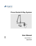
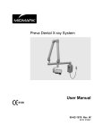
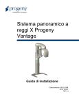
VetVision DC X-Ray System User Manual 00-02-1601 Rev. G ECN: P3250 Attention: The equipment must only be installed and operated in accordance with the safety procedures and operating instructions given in this manual and in the User Manual for the purposes and applications for which it was designed. Modifications and/or additions to the equipment may only be carried out by Progeny – A Midmark Company or by third parties expressly authorized to do so. Such changes must comply with legal requirements as well as with the generally accepted technical rules. It is the responsibility of the user to ensure that existing legal regulations regarding installation of the equipment with respect to the building are observed. X-RAY PROTECTION: X-ray equipment may cause injury if used improperly. The instructions contained in this manual must be read and followed when operating the Vet Vision. Your Dental dealer will assist you in placing the Vet Vision in operation. The Vet Vision X-Ray System provides a high degree of protection from unnecessary x-radiation. However, no practical design can provide complete protection nor prevent operators from exposing themselves or others to unnecessary radiation. VetVision DC VetVision DC Dental X-Ray System User Manual Progeny – A Midmark Company 675 Heathrow Drive Lincolnshire, IL 60069 Phone: +1-847-415-9800 Toll Free: (888) 924-3800 Fax: (847) 415-9810 www.progenyvetimaging.com © Progeny Dental 2008, U.S. Patents D470237, D469182, D470589, 6,837,468, and 6,664,853 VetVision DC Table of Contents Table of Contents ............................................................................................ i General Information ....................................................................................... 1 VetVision DC Dental X-ray (Wall-mounted Model) ..................................... 1 VetVision DC Dental X-ray Mobile System).................................................2 Compliance with Applicable Standards ...................................................... 3 Certified Components ................................................................................. 3 EC Declaration of Conformity ..................................................................... 4 Authorized Representatives........................................................................ 5 Safety ......................................................................................................... 5 Explanation of Symbols on Technical Labels ............................................. 6 Obtaining Technical Support ...................................................................... 6 Operating the VetVision DC Dental X-Ray System ........................................ 7 Using the Operator Panel ........................................................................... 8 Taking an X-Ray Using Preset Techniques ................................................ 9 Pre-programmed Exposure Times............................................................ 11 Baseline Technique Charts - Canine........................................................ 12 Feline Technique Settings.........................................................................13 Record Your Exposure Settings- Canine.................................................. 14 Record Your Exposure Settings- Feline.................................................... 15 System Configuration ................................................................................... 16 System Configuration Mode ..................................................................... 16 Adjusting the Display ................................................................................ 17 Changing Pre-programmed Exposure Settings ........................................ 18 Showing Current System Configuration .................................................... 20 Diagnostic Mode ....................................................................................... 21 Trouble Shooting .......................................................................................... 21 Performance Issues .................................................................................. 22 Technical Support ..................................................................................... 22 Recommended Maintenance ....................................................................... 23 Regular Maintenance ............................................................................... 23 Cleaning and Disinfecting ......................................................................... 23 Checking System Functions ......................................................................... 24 System Function Checklist ....................................................................... 25 New Tube Seasoning Procedure .............................................................. 26 Specifications ............................................................................................... 27 VetVision DC Dental X-Ray System ......................................................... 27 Tube Rating Charts....................................................................................28 VetVision DC General Information VetVision DC Dental X-ray (Wall-mounted Model) 1 00-02-1601 Rev F VetVision DC VetVision DC Mobile System 2 00-02-1601 Rev F VetVision DC Compliance with Applicable Standards Radiation Protection The certified components of the VetVision DC X-Ray System comply with Radiation Performance Standards 21 CFR, Subchapter J, at the time of manufacture. The certified components of the VetVision DC X-Ray System comply with IEC 60601-1-3 Radiation protection/x-ray equipment. UL 2601-1 File Number: E181750 EMI/EMC Classified by Underwriters Laboratories Inc. with respect to electrical shock, fire and mechanical hazards only in accordance with UL 2601-1, and CAN/CSA C22.2 NO, 601.1-M90, and to the following particular standards, IEC60601-2-7, IEC60601-2-28. IEC60601-1-2 Certified Components System Component Tubehead Control Unit Cone 8 in. Reference Number 30-A1027 30-A1041 30-A2016 3 00-02-1601 Rev F VetVision DC EC Declaration of Conformity Name and Description of Product Progeny VetVision DC Catalog Model P7017V, 76 inch reach 30-A1041, Control 30-A1028, Articulated Arm Catalog Model P7016V, 66 inch reach 30-A1041, Control 30-A1028, Articulated Arm Catalog Model P7015V, 56 inch reach 30-A1041, Control 30-A1028, Articulated Arm Catalog Model P7017VM, Mobile 30-A1032, Control Class: IIb Reference Numbers to which Conformity is Declared The following regulatory documents apply: UL 2601-1 IEC 60601-1-2 IEC 60601-1-3 IEC 60601-2-7 IEC 60601-2-28 IEC 60601-2-32 Contact Technical Support [email protected] Authorized Representatives 4 00-02-1601 Rev F VetVision DC North America Europe Midmark Corporation 675 Heathrow Dr. Lincolnshire, IL 60089 Phone: 888-924-3800 Fax: 847-415-9810 Safety CE Partner 4U Esdoornlaah 13 3951DB Maarn Netherlands Phone: +31.343.442.524 Fax: +31.343.442.162 5 00-02-1601 Rev F VetVision DC Only qualifi ed and author ized perso nnel may operat e this equip ment obser ving all laws and regula tions conce rning radiati on protec tion. • T h e o p er at or at all ti m e s m u st re m ai n 6f t. (2 m ) fr o m 00-02-1601 RevthF e fo Ra di ati on Sa fet y 6 VetVision DC 7 • O nl y q u ali fi e d a n d a ut h or iz e d s er vi c e p er s o n n el s h o ul d re m o v e c o v er s o n th e e q ui p m e nt . • T hi 00-02-1601 RevsF e q El ec tri cal Sa fet y VetVision DC Ex pl os io n Sa fet y 8 This equipm ent must not be used in the presen ce of flamma ble or potenti ally explosi ve gases or vapors, which could ignite, causing person al injury and/or damag e to the equipm ent. If such disinfec tants are used, the vapor must be allowed to dispers e before using the equipm ent. 00-02-1601 Rev F VetVision DC 9 00-02-1601 Rev F VetVision DC Explan ation of Symb ols on Techni cal Labels Typ e B: Prot Con sult writt AT TE NTI WA RNI NG XRA Y Mai ns HO Mai ns NE Eart h Gro Obtaini ng Techni cal Suppor 10 00-02-1601 Rev F VetVision DC t Co nt ac t Pro gen y– A Mid mar k Co mp any 675 Hea thro w Driv e Linc olns hire , IL 600 69 Pho ne: +1847 415 980 0 Toll Fre e:8 88924 380 0 Fax : +1- 11 00-02-1601 Rev F VetVision DC 847 415 981 0 tec hsu ppo rt@ pro gen yde ntal .co m Serial Number Location SN numbers are located on the tube head or on the base of mobile systems. 12 00-02-1601 Rev F VetVision DC Operating the VetVision DC Dental X-Ray System Using the Operator Panel ICONS 1. Large, LED screen displays technique settings. It also displays menu selections when the system is in menu mode. 2. Up and Down arrows are used to change kV, mA and time settings. 3. Tooth Icon. Pressing this button allows the user to select Upper or Lower Canine, Incisors, Premolars and Molars. 4. Receptor Icon. Choices are: Digital, D Speed film, E/F Speed Film. If using phosphor plates, select E/F Speed Film Setting. 5. Patient Size Icon. Press to select Large or Small 6. Ready Indicator. Circle lights up to indicate that the system is ready to produce x-ray. 7. Right Arrow Button. Use this button to move between kV, mA and time selections. This button is also used as an “Enter” key when the system is in menu mode. 8. Radiation Indicator. This symbol lights up when an x-ray is produced. 9. Exposure Button. Pressing this button will produce an x-ray exposure. 13 00-02-1601 Rev F VetVision DC Using the Operator Panel Power On Settings When the VetVision DC is powered on, the Operator Panel will display the selections that were used when the system was last powered off. Display The Operator Panel displays the exposure settings (kV, mA, and exposure time) for the currently selected tooth, image receptor type, and patient size. Selecting Techniques To select the desired technique for a procedure: 1. Press the Tooth Selection Icon until the correct tooth anatomy is lit. 2. Press the Image Receptor Icon to select the type of receptor you will be using. 3. Press the Patient Size Icon to choose large or small. The appropriate kV, mA and time settings will now appear in the display and the system is ready to take an x-ray. Technique Tables For a table of the factory-programmed exposure settings, refer to the Pre-programmed Exposure Settings tables on page 11. Adjusting Exposure Settings Preset exposure settings can be adjusted prior to making an exposure. Use the right arrow to select the exposure setting to adjust. Then use the up and down arrow buttons to adjust the value. • To save new presets, refer to System Configuration mode on page 16. Exposure Button and Ready Indicator The Exposure button is used to initiate an x-ray exposure. For a complete exposure, the button must be pressed and held until the Radiation Indicator no longer illuminates and the audible signal is no longer heard. Releasing the Exposure button immediately terminates the x-ray exposure. CAUTION! Releasing the Exposure button prior to the completion of the x-ray exposure will result in an incomplete exposure of the image. This may require the operator to re-take the radiograph. When a premature release of the Exposure button occurs, the system will notify the operator by blinking momentarily, then it will return to operating mode. Ready Indicator The Ready Indicator lights up when the system is ready to make an exposure Immediately after an exposure, the Ready Indicator flashes until the x-ray tube cools down sufficiently to make the next exposure. When the Ready Indicator is flashing,no exposure can be made. Radiation Indicators The VetVision DC has a visible and an audible Radiation Indicator. When an exposure is in progress, the Radiation Indicator on the Operator Panel is illuminated and an audible tone is heard. The exposure is complete when the Radiation Indicator light is extinguished and the audible tone is no longer heard. 14 00-02-1601 Rev F VetVision DC Taking an X-Ray Using Preset Techniques 1. The power switch is located at the upper right of the Control Unit or on the control unit on the footed stand of the mobile system. Press button to the “On” position. The Ready Indicator on the front of the Operator Panel will light. 2. Verify that the unit is set for the Tooth to be imaged. The icon for the currently selected Tooth is illuminated. To change, press the Tooth Selection button until the correct tooth type is selected. 3. Verify that the unit is set for the correct Image Receptor Type. The icon for the currently selected Image Receptor Type will be illuminated. To change the Image Receptor type, press the Image Receptor button until the correct Image Receptor Type is selected. 4. Verify that the system is set for the appropriate Patient Size. The icon for the currently selected Patient Size will be illuminated. To change Patient Size, press the Patient Type button to select Large or Small. 5. Make sure the patient is properly immobilized and place the tube head 2-3 inches from the patient and directly centered on the receptor. 6. Press and hold the Exposure button until the audible signal is no longer heard and the Radiation Indicator is no longer illuminated. Releasing the Exposure button or coil-cord hand switch at any time will immediately terminate the exposure. Note: When using the coil-cord hand switch, it is recommended that the operator exit the operatory if possible. Note: In order to comply with regulations and good safety practices, the technique factors must be visible to the operator from the remote location. 7. Return the Tubehead to the storage position. Note: Be careful not to strike the Tubehead on the wall when returning it to the storage position. 15 00-02-1601 Rev F VetVision DC Changing kV, mA or time If it becomes necessary to increase or decrease the kV, mA, or time from the preset values, follow these steps: 1. 2. 3. 4. Press the Enter button to highlight the current kV, mA or time setting. Use the up and down buttons to increase or decrease the value. Press the Exposure button. After the image(s) has been captured, press any of the tooth, receptor type or patient size buttons to return the display to its preset values. Note: When exposure settings are being adjusted, the Tooth Selection, Image Receptor Type, and Patient Size buttons are not illuminated. 16 00-02-1601 Rev F VetVision DC Pre-programmed Exposure Times The tables below show the factory default exposure settings for each combination of Tooth, Image Receptor Type, and Patient Size on the Operator Panel. These exposure settings can be modified using the System Configuration mode. See the System Configuration section for details. 8" Cone Progeny Setting Schick Dexis Kodak Sirona PSP D Speed E/F Speed Large Small Large Small Large Small Large Small Large Small Large Small Large Small Large Small kV 65 65 65 65 60 60 65 65 65 65 65 65 65 65 65 65 mA 7 7 7 7 7 7 7 7 7 7 7 7 7 7 7 7 Sec 0.100 0.080 0.080 0.050 0.125 0.080 0.100 0.064 0.080 0.050 0.125 0.080 0.250 0.160 0.125 0.080 Lower kV 65 65 65 65 60 60 65 65 65 65 65 65 65 65 65 65 Canine mA 7 7 7 7 7 7 7 7 7 7 7 7 7 7 7 7 Sec 0.080 0.064 0.064 0.040 0.100 0.080 0.080 0.064 0.064 0.040 0.100 0.080 0.200 0.160 0.100 0.080 65 Upper Canine Incisors Premolars Molars kV 65 65 65 65 60 60 65 65 65 65 65 65 65 65 65 mA 7 7 7 7 7 7 7 7 7 7 7 7 7 7 7 7 Sec 0.100 0.080 0.064 0.040 0.100 0.080 0.080 0.064 0.064 0.040 0.100 0.080 0.200 0.160 0.100 0.080 65 kV 65 65 65 65 60 60 65 65 65 65 65 65 65 65 65 mA 7 7 7 7 7 7 7 7 7 7 7 7 7 7 7 7 Sec 0.100 0.080 0.064 0.040 0.100 0.080 0.080 0.064 0.064 0.040 0.100 0.080 0.200 0.160 0.100 0.080 65 kV 65 65 65 65 60 60 65 65 65 65 65 65 65 65 65 mA 7 7 7 7 7 7 7 7 7 7 7 7 7 7 7 7 Sec 0.125 0.080 0.080 0.050 0.125 0.080 0.100 0.064 0.080 0.050 0.125 0.080 0.250 0.160 0.125 0.080 12" Cone Progeny Setting Schick Dexis Kodak Sirona PSP D Speed E/F Speed Large Small Large Small Large Small Large Small Large Small Large Small Large Small Large Small kV 65 65 65 65 60 60 65 65 65 65 65 65 65 65 65 65 mA 7 7 7 7 7 7 7 7 7 7 7 7 7 7 7 7 Sec 0.200 0.160 0.160 0.100 0.250 0.160 0.200 0.125 0.160 0.100 0.250 0.160 0.500 0.320 0.250 0.160 Lower kV 65 65 65 65 60 60 65 65 65 65 65 65 65 65 65 65 Canine mA 7 7 7 7 7 7 7 7 7 7 7 7 7 7 7 7 Sec 0.160 0.125 0.125 0.080 0.200 0.160 0.160 0.125 0.125 0.080 0.200 0.160 0.400 0.320 0.200 0.160 65 Upper Canine Incisors Premolars Molars kV 65 65 65 65 60 60 65 65 65 65 65 65 65 65 65 mA 7 7 7 7 7 7 7 7 7 7 7 7 7 7 7 7 Sec 0.200 0.160 0.125 0.080 0.200 0.160 0.160 0.125 0.125 0.080 0.200 0.160 0.400 0.320 0.200 0.160 65 kV 65 65 65 65 60 60 65 65 65 65 65 65 65 65 65 mA 7 7 7 7 7 7 7 7 7 7 7 7 7 7 7 7 Sec 0.200 0.160 0.125 0.080 0.200 0.160 0.160 0.125 0.125 0.080 0.200 0.160 0.400 0.320 0.200 0.160 65 kV 65 65 65 65 60 60 65 65 65 65 65 65 65 65 65 mA 7 7 7 7 7 7 7 7 7 7 7 7 7 7 7 7 Sec 0.250 0.160 0.160 0.100 0.250 0.160 0.200 0.125 0.160 0.100 0.250 0.160 0.500 0.320 0.250 0.160 * Large = over 40 lbs. *Small = under 40 lbs. 17 00-02-1601 Rev F VetVision DC Baseline Technique Charts – Canine Baseline Technique Charts D speed film Small Dog kV mA Secs Medium Dog kV mA Secs Maxillary incisors 60 7 0.25 Maxillary canine 60 7 0.32 Maxillary anterior premolars 60 7 0.32 Maxillary PM4 60 7 0.32 Maxillary PM4 caudal view 60 7 0.40 Maxillary M1 M2 60 7 0.40 Mandibular incisors 60 7 0.25 Mandibular canine 60 7 0.32 60 7 0.25 60 7 0.25 Mandibular anterior premolars (lateral oblique view) Mandibular posterior pm & molars Digital Small Dog kV mA Medium Dog Secs. kV mA Secs. Maxillary incisors 60 6 0.08 Maxillary canine 60 6 0.08 Maxillary anterior premolars 60 6 0.08 Maxillary PM4 60 6 0.08 Maxillary PM4 caudal view 60 6 0.10 Maxillary M1 M2 60 6 0.10 Mandibular incisors 70 6 0.04 Mandibular canine 60/70 7/6 0.08 /0.05 60 6 0.064 65 6 0.032 Mandibular anterior premolars (lateral oblique view) Mandibular posterior pm & molars Large Dog kV mA Secs Large Dog kV mA Secs. 18 00-02-1601 Rev F VetVision DC Feline Technique Settings D speed film kV mA Secs Maxillary incisors 60 7 0.1 Maxillary canine 60 7 0.1 Maxillary premolars M1 intraoral 60 7 0.1 Maxillary premolars M1 extraoral 60 7 0.125 Mandibular incisors and canine 60 7 0.1 Mandibular PM3 lateral oblique 60 7 0.16 Mandibular PM3 M1 60 7 0.1 kV mA Secs. Maxillary incisors 60 7 0.032 Maxillary canine 60 7 0.032 Maxillary premolars M1 intraoral 60 7 0.04 Maxillary premolars M1 extraoral 60 7 0.05 Mandibular incisors and canine 60 7 0.032 Mandibular PM3 lateral oblique 65 7 0.025 Mandibular PM3 M1 65 7 0.025 Digital 19 00-02-1601 Rev F VetVision DC Record Your Exposure Settings If the pre-programmed exposure settings do not produce the density desired, adjust the settings using System Configuration mode. Record your settings in the table below. Canine * Large = more than 30 lbs.. * Small = 30 lbs. and under 20 00-02-1601 Rev F VetVision DC Record Your Exposure Settings If the pre-programmed exposure settings do not produce the density desired, adjust the settings using System Configuration mode. Record your settings in the table below. Feline *Use small settings for feline dentistry 21 00-02-1601 Rev F VetVision DC System Configuration System Configuration Mode About System Configuration Mode Using System Configuration Mode The VetVision DC Dental X-Ray System has a software-driven system configuration mode. When the VetVision DC is in system configuration mode, you can perform the following procedures: • Adjusting the Display • Changing Pre-programmed Exposure Settings • Changing the Cone Size • Showing Current System Configuration • Displaying Diagnostic Data 1. To enter system configuration mode, depress the Tooth Selection and Patient Size Selection buttons on the Operator Panel simultaneously for 5 seconds. The display shows the Main System Configuration menu, as shown in Figure 1, and the Ready Indicator blinks. 2. To select menu items while in system configuration mode, use the up and down arrows to highlight a menu option. Then use the right arrow button as an Enter button to select the highlighted option. When changing presets, the right arrow button is also used to select the technique factor. 3. After selecting a menu option, use the up and down arrows to increase or decrease values. Figure 1 Main System Configuration Menu 22 00-02-1601 Rev F VetVision DC Adjusting the Display Adjusting Contrast Reversing the Image The VetVision DC Dental X-Ray System allows the operator to adjust the display image. 1. From the system configuration main menu, shown in Figure 1, select ADJUST DISPLAY. You will see the Display Options menu shown in Figure 2. 2. Selecting EXIT returns the display to the Main System Configuration menu shown in Figure 1. 1. Select ADJUST CONTRAST from the menu. You will see the Progeny logo. 2. Use the up and down arrows to increase or decrease the contrast between the menu text and the display background. 3. Press the right arrow to save your settings. 1. Select REVERSE IMAGE from the menu. The text and display background colors will be swapped. 2. Press the right arrow to save your settings. Figure 2 Display Options Menu 23 00-02-1601 Rev F VetVision DC Changing Pre-programmed Exposure Settings Displaying the Preset Options Menu The VetVision DC Dental X-Ray System allows the operator to increase or decrease image density for all presets for a receptor simultaneously or to change each of the technique factors for a preset individually. You can also restore factory default settings. For charts of the factory default settings, refer to Factory Default Exposure Settings later in this manual. Note: Before changing presets, use the table on page 14 to write down the presets you are programming. 1. From the Main System Configuration menu, shown in Figure 1, select CHANGE PRESETS. You will see the Preset Options menu shown in Figure 3. 2. Selecting EXIT returns the display to the Main System Configuration menu shown in Figure 1. Figure 3 Preset Options Menu Changing All Receptor Settings Globally 1. Select ALTER DENSITIES from the Preset Options menu. The first Image Receptor Type illuminates. The display shows the selected Image Receptor Type and current density. 2. Using the Image Receptor Type button, select the image receptor to adjust. 3. Use the up and down arrow buttons to specify a percentage by which densities will be increased or decreased for the selected receptor. Densities can be increased or decreased according to values provided on the display. 4. Press Enter to save your settings. 24 00-02-1601 Rev F VetVision DC 1. Energize the system. Preprogramming 2. Press the Tooth Selection and Patient Size Selection buttons for five full to Digital seconds. Sensors 3. Select CHANGE PRESETS from the Menu Options screen. 4. Select SELECT RECEPTOR from the Preset Options menu (Figure 3). 5. Press the up or down button to highlight the sensor or phosphor plate to change, and press Enter. 6. Select YES or NO on the Verification screen. 7. Exit the Preset Options menu. 8. Exit the Menu Options menu. A message of “Saving Settings” will display briefly, and then the system will return to the normal operational mode. Note: When you are working in service mode, the green light next to the exposure button will blink. Changing Presets Individually Recall Presets 1. Select EDIT PRESETS from the Preset Options menu. The display notifies you that you are entering Edit Preset Mode, and Tooth Size, Image Receptor Type, and Patient Size are illuminated. 2. Use the Tooth Selection, Image Receptor Type, and Patient Size Selection buttons to select the preset to change. The display shows the current values for the preset. 3. Use the right arrow button to display the technique factor to change. 4. Use the up and down arrow buttons to set the value for the selected technique factor and preset. 5. Repeat steps 2-4 to change additional presets. 6. When you have completed all changes, press the Tooth Selection and Patient Size Selection buttons simultaneously for 5 seconds to record the change. 1. To return all presets to factory defaults, select RECALL PRESETS from the Preset Options menu. The menu will ask you to confirm your choice. 2. Select YES using the up arrow button and return all presets to factory default settings. Selecting YES will erase any custom presets that have been set up. 3. Select NO using the down arrow button and retain current presets. To retain the presets, select YES. 25 00-02-1601 Rev F VetVision DC Showing Current System Configuration The VetVision DC Dental X-Ray System displays the current system configuration. This display is informational only. 1. From the Main System Configuration menu, shown in Figure 1, select CONFIGURE UNIT. You will see the Configuration menu shown in Figure 4. 2. Select SHOW CONFIG. The display will show: • Current software version • Cone size • Diagnostic mode on or off 3. Press any button on the Operator Panel to return to the Configuration menu. Figure 4 Configuration Menu 26 00-02-1601 Rev F VetVision DC Diagnostic Mode About Diagnostic Mode Showing the Maintenance Summary Figure 5 Set Configuration Menu The VetVision DC Dental X-Ray System has a diagnostic mode in which you can display a summary of maintenance data or display feedback values after each exposure. 1. From the Main System Configuration menu, shown in Figure 1, select CONFIGURE UNIT. 2. You will see the Configuration menu, shown in Figure 4. 3. To display a summary of maintenance data, highlight select SHOW MAINT. The following maintenance data are displayed: • Total KJ (kilojoules—total system heat on x-ray tube) • Exposure Count • Reboots (power up cycles) • OT Counts (over-threshold counts) 4. Press any button on the Operator Panel to return to the Configuration menu. If you take an x-ray while in diagnostic mode, the display shows feedback values for that exposure. Until you exit diagnostic mode, the display will continue to show feedback values after each exposure. 1. From the Main System Configuration menu, shown in Figure 1, select CONFIGURE UNIT. You will see the Configuration menu shown in Figure 4. 2. Select SET CONFIG. You will see the Set Configuration menu, shown in Figure 5. 3. From the Set Configuration menu, use the up and down arrows to highlight DIAG MODE ON. Press the right arrow button to turn on diagnostic mode. 4. Exit System Configuration mode by highlighting and selecting EXIT in the Configuration and Main menus. 5. Make an exposure. The display will show the following feedback values: • kV • mA • Filament current 6. Press any button on the Operator Panel to clear the feedback values from the display. 7. To exit diagnostic mode, depress the Tooth Selection and Patient Size Selection buttons simultaneously for 5 seconds to display the Main System Configuration menu. From the Main System Configuration menu, highlight and select CONFIGURE UNIT. Then highlight and select SET CONFIG. On the Set Configuration menu, highlight and select DIAG MODE OFF. 27 00-02-1601 Rev F VetVision DC Trouble Shooting Performance Issues Light or dark images No X-Ray Pre-termination Error 1. Adjust the selected exposure time, kilovoltage or tube current to produce an acceptable image. If necessary, reprogram the techniques factors, as explained in the System Configuration section of this manual. 2. Verify the kilovoltage and tube current during an exposure using the diagnostic mode, as explained in the System Configuration section of this manual. Alternatively, you may employ a non-invasive meter to evaluate kilovoltage and exposure time. 3. Inspect the condition of the remaining imaging chain components such as the film, chemistry and processor, or the condition of the x-ray sensor and computer. If no x-ray is produced, check the following: 1. Verify that the line cord (if one is in use) is properly connected. 2. Verify that the power switch is in the ON position. Early release of the exposure switch will cause a pre-termination error to occur. After five seconds, the system will return to the normal operating condition. Be advised that this will result in an underexposed image. Technical Support Contact PROGENY DENTAL 675 Heathrow Drive Lincolnshire, IL 60069 Phone: +1-847-415-9800 Toll Free: 888-924-3800 Fax: +1-847-415-9810 [email protected] 28 00-02-1601 Rev F VetVision DC Recommended Maintenance Regular Maintenance In the interest of equipment safety, a regular maintenance program must be established. This maintenance program should consist of cleaning and disinfecting as well as annual system function checking. It is the owner’s responsibility to arrange for this service and to assure that the personnel performing this are fully qualified to service Progeny Dental x-ray equipment. Cleaning and Disinfecting Cleaning Compounds Cleaning Methods The VetVision DC Dental X-Ray System requires disinfection. The cleaning and disinfecting methods described here protect operators and patients in a manner that is safe for the equipment. Progeny Dental recommends the use of disinfectant products, such as Discide Ultra®, Cavicide® or the equivalent. Between each patient, perform the following cleaning and disinfecting steps. 1. Remove gross bio-burden from the cone, handles and structure with a disposable towel moistened with water. 2. Dry the cone, handles and structure with disposable towels. 3. Wipe the cone, handles and structure with the disinfectant product following the disinfectant manufacturer’s instructions. 4. Clean any remaining disinfectant from the component with water. This additional step prevents possible product discoloration or corrosion. 5. Dry the cone, handles and structure with disposable towels. Caution! The Progeny Dental X-Ray System is not waterproof. Use only moistened, not saturated, towels. 29 00-02-1601 Rev F VetVision DC Checking System Functions The following checks must be performed to complete the installation of the VetVision DC Dental X-Ray System and as part of the recommended maintenance as indicated in the User Manual. CAUTION! If the VetVision DC Dental X-Ray System does not perform the functions below, advise the owner that the system is not to be used. See the Troubleshooting section of this manual or contact Progeny’s Technical Support. 30 00-02-1601 Rev F VetVision DC System Function Checklist Wall Mounting Ensure that the wall support is adequate and that the system is properly mounted to the wall. Labels Ensure that all certified components bear labels that include the model and serial number, date of manufacture and a statement of certification as noted elsewhere in this manual. Tubehead Check for oil leaks or other evidence that could indicate internal damage. Replace the Tubehead, if necessary. Tubehead Rotation Ensure that the Tubehead maintains its position around the horizontal axis while remaining easy to rotate and position. Also check the vertical pivot of the Tubehead for easy movement while remaining in position after moving. Check that all movements are smooth and quiet. Verify that the Tubehead is properly counterbalanced for vertical drift and that the Horizontal and Articulating Arms do not drift horizontally. Power Switch Verify that the switch is working properly and that the Ready Indicator is illuminated when the power switch is in the ON position. Operator Panel Controls With the power switch, located at the upper right of the Control Unit, in the ON position, verify that technique factors appear on the Operator Panel. Also, check the function of the selection buttons for Tooth Selection, Image Receptor Type and Patient Size. Pressing a selection Exposure Button Verify that the Exposure button on the Operator Panel is functioning properly. To make an exposure, press and hold the Exposure button until the Radiation Indicator is extinguished and the audible signal is no longer heard. Suspension Exposure Indicators Premature Termination Coil-cord Hand Switch Make several exposures and verify that the Radiation Indicator illuminates and the audible signal is heard. Select the longest exposure time possible using the up and down arrows. Initiate an exposure but release the Exposure button after a brief period of time before the timer terminates the exposure. Verify that the display indicates “Pre-termination Error” and returns to normal operating mode. When a coil-cord hand switch is used, inspect the switch housing and coil cord for damage or wear. Replace if evidence of damage is present. User Information Make certain that the user of the system has received the User Manual. 31 00-02-1601 Rev F VetVision DC New Tube Seasoning Procedure X-ray tubes that sit dormant for several months can become electrically unstable. To remedy this condition, it is recommended you perform a “new tube seasoning procedure.” This process establishes stable high voltage operation and will ultimately extend the life of the tube. Repeat this procedure before returning to normal operation any time the system has been unused for more than two months. 1. Verify system operation. 2. Energize the system. 3. Select 60 kilovolts, 7 milliamperes, and the exposure time of one second. 4. Make five exposures at this level, observing the normal cooling time. 5. Select 65 kilovolts, 7 milliamperes, and the exposure time of one second. 6. Make five exposures at this level, observing the normal cooling time. 7. Select 70 kilovolts, 6 milliamperes, and the exposure time of one second. 8. Make five exposures at this level, observing the normal cooling time. 32 00-02-1601 Rev F VetVision DC Specifications VetVision DC Dental X-Ray System The following specifications contain information required to be provided to the user per Federal Regulation 21 CFR. Line Voltage 100-230 VAC +/- 10% 50/60 Hz Line Load Max. current 5 amps Maximum Rated Tube Potential 70 KVp kVp Accuracy +/- 5% selectable Tube Current 4-7 mA +/- 1 mA Exposure Time 20 ms through 2.00 seconds Timer Accuracy 5% +/- 1 ms Source to Skin Distance 8 inch (20 cm) Minimum Half Value Layer 1.7 mm Aluminum equivalent at 70 kVp Minimum Inherent Filtration 2 mm Aluminum equivalent at 70 kVp Focal Spot 0.4 mm (IEC 336) Automatic Cooling Time 15 times the exposure time wait before the next exposure can begin Leakage Technique Factors 1.5 mA at 70 kVp Target Angle 12.5 degrees Operating Temperature +50 F/+95 F (+10 C/+35 C) Storage Temperature -31F/+150 F (-35 C/+66 C) Maximum Altitude 12,000 ft Cone Focal Length 8 inch (20 cm) Diameter of X-Ray 2.7 inch (6.9 cm) at the end of the Cone Specifications for optional cones differ 33 00-02-1601 Rev F VetVision DC Figure 7 Toshiba Tube Rating Charts 34 00-02-1601 Rev F VetVision DC Rating Chart Thermal Characteristics Chart Figure 8 Kailong Tube Rating Charts 35 00-02-1601 Rev F