1
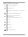
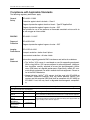
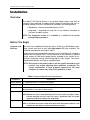
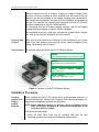
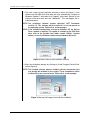
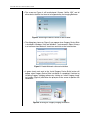
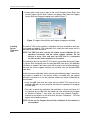
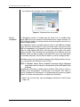
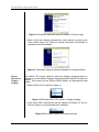
VETPRO VDX
®
D IGITAL S ENSOR S YSTEM
USER AND INSTALLATION GUIDE
00-02-1673 Rev. C (ECN P2883)
VETPRO® VDX
DIGITAL SENSOR SYSTEM
USER AND INSTALLATION GUIDE
00-02-1673 REV. C
MIDMARK CORPORATION
675 HEATHROW DRIVE
LINCOLNSHIRE, IL 60069, U.S.A.
PHONE +1 (847) 415-9800
TOLL FREE (888) 924-3800 (U.S. ONLY)
FAX: +1 (847) 415-9810
WWW.PROGENYDENTAL.COM
Copyright © 2011 Midmark. All rights reserved.
VetPro® VDX: User and Installation Guide
TABLE OF CONTENTS
General Information.................................................................................................................... 4
Indications for Use ............................................................................................................... 4
Contraindications ................................................................................................................. 4
Warnings/Precautions .......................................................................................................... 4
Product Description.............................................................................................................. 5
Explanation of Symbols on Technical Labels ........................................................................ 6
Compliance with Applicable Standards ................................................................................ 7
Obtaining Technical Support ................................................................................................ 9
Authorized Representatives .................................................................................................. 9
Installation ................................................................................................................................ 10
Overview ............................................................................................................................ 10
Before You Begin ................................................................................................................ 10
Installation Procedure ......................................................................................................... 11
Operating the VetPro® VDX Sensor .......................................................................................... 18
Acquiring Images................................................................................................................ 18
Using the Sensor Sheaths .................................................................................................. 19
Using a Sensor Positioning Device ........................................ Error! Bookmark not defined.
Recommended Maintenance.............................................................................................. 19
Cleaning and Disinfecting ................................................................................................... 19
Specifications........................................................................................................................... 21
X-Ray Sensor ..................................................................................................................... 21
Environmental ..................................................................................................................... 21
Terms ....................................................................................................................................... 22
Warranty ................................................................................................................................... 22
00-02-1673 © 2011 Midmark • 675 Heathrow Drive, Lincolnshire, IL 60069, U.S.A. • Phone +1 (847) 415-9800
3
VetPro® VDX: User and Installation Guide
General Information
Indications for Use
VetPro® VDX is intended to be used by veterinarians and other qualified professionals for producing diagnostic x-ray radiographs of dentition, jaws and other oral structures.
Contraindications
None known.
Warnings/Precautions
Radiation
Safety
• Only qualified and authorized personnel may operate this equipment observing all laws and regulations concerning radiation protection.
• The operator at all times must remain at a safe distance from the focal
spot and the X-ray beam for operator protection.
• Full use must be made of all radiation safety features on the X-ray equipment.
• Full use must be made of all radiation protection devices, accessories and
procedures available to protect the patient and operator from X-ray radiation.
Electrical
Safety
• The VetPro® VDX sensor cable should be handled with care. Do not sharply bend or crimp the sensor cable. Doing so could permanently damage
the sensor.
• This equipment must only be used in rooms or areas that comply with all
applicable laws and recommendations concerning electrical safety in
rooms used for medical purposes, e.g., IEC, US National Electrical code,
or VDE standards.
• Before cleaning or disinfecting, this equipment must always be disconnected from the electrical supply.
• The computer and any other associated equipment (like USB hub) shall be
placed outside the patient’s environment (i.e.: more than 1.5 meters away
from the table). The operator shall not access the patient and such devices
at the same time.
• The computer and any other associated equipment shall be compliant with
IEC 60950 or IEC 60601.
Patient
Safety
• Prior to use always cover the sensor with a disposable hygienic protective
cover. A new cover must be used for each patient. It is recommended to
disinfect the sensor between uses.
• The VetPro® VDX, Computer, and provided cables comprise a Medical
Electrical System. The Computer is not intended to be located in the patient environment (within a 1.5 m radius of the patient).
• System installation shall be in accordance with the requirements of
IEC 60601-1, the Standard for Safety Requirements of Medical Electrical
Systems
00-02-1673 © 2011 Midmark • 675 Heathrow Drive, Lincolnshire, IL 60069, U.S.A. • Phone +1 (847) 415-9800
4
VetPro® VDX: User and Installation Guide
Product Description
VetPro® VDX is a digital imaging system for dental radiographic application.
The product is to be used for routine dental radiographic examinations such
as bitewings, periapicals, etc. Two different sized sensors (size 1 and size 2)
are utilized to image different anatomy and for different patient sizes. The
CMOS sensor connects directly to a USB connection in a PC without the
need for an intermediate electrical interface. VetPro® VDX works with a standard dental intraoral x-ray source without any connection to the x-ray source.
VetPro® VDX captures an image automatically upon sensing the production of
x-ray and after the x-ray is complete, transfers the image to an imaging software program on the PC. Disposable sheaths are used with each use to prevent cross-contamination between patients. VetPro® VDX Sensor is a state of
the art intraoral x-ray detector intended for digital imaging of teeth and the
oral cavity. The system provides:
• Immediate production of an image
• Digital image storage and management
• Efficient archiving and recall of images
• Elimination of film processing
The components of the VetPro® VDX sensor system are the Digital Sensor internal USB Cables and, the Sensor Calibration Files.
Digital Sensor
The digital sensor is designed to transform a two dimensional X-ray picture
into an electrical signal. The structure of the sensor is assembled with a first
layer of phosphor material (scintillator) which, when exposed by incident Xrays, emits a luminous radiation. This light is then transferred to the photo
sensitive elements of the Sensor where it is transformed to electrical potential.
The electrical signal is sent to the computer for processing.
Sensor
Calibration
Files
During installation of the VetPro® VDX sensor system, files specific to the sensor serial number are stored on each computer where the sensor will be used.
For more details, refer to the VetPro® VDX Installation section of this manual.
Progeny
Imaging
Provides the user interface to acquire, store, retrieve, transmit, review and
post process images acquired by the VetPro® VDX sensor system. For more
details refer to the VetPro® VDX Installation section of this manual or the Progeny Imaging User Manual.
NOTE
The VetPro® VDX digital sensor is sensitive to intense UV light. Therefore, the
sensor should be stored in the box provided and never exposed to direct sunlight for extensive periods of time.
00-02-1673 © 2011 Midmark • 675 Heathrow Drive, Lincolnshire, IL 60069, U.S.A. • Phone +1 (847) 415-9800
5
VetPro® VDX: User and Installation Guide
Explanation of Symbols on Technical Labels
Caution, consult accompanying documents
Refer to operating instructions
Class II equipment – provides double Isolation to protect against electric
shock
Type BF – provides additional protection against electric shock
Degree of protection – IP67 means that sensor casting is :
totally protected against dust,
protected against the effect of immersion between 15 cm and 1 m.
Direct current
Serial number
Catalogue number
Date of manufacture
Place of manufacture (manufacturer)
00-02-1673 © 2011 Midmark • 675 Heathrow Drive, Lincolnshire, IL 60069, U.S.A. • Phone +1 (847) 415-9800
6
VetPro® VDX: User and Installation Guide
Compliance with Applicable Standards
The following regulatory documents apply:
General
Safety
IEC 60601-1:1995
Protection against electrical shock – Class II
Degree of protection against electrical shock – Type BF Applied Part
Degree of protection against ingress of water – IP67
Not suitable for use in the presence of flammable anesthetic mixture with air
or with oxygen or nitrous oxide.
EMI/EMC
IEC 60601-1-2:2007
Degree of
Protection
IEC 60529: 2001
Imaging
Performance
IEC 61223-3-4:200
Degree of protection against ingress of water – IP67
Line pair resolution – better than 8 lp/mm
Low contrast resolution – all holes visible
EMC
Statement
Information regarding potential EMC interference and advice for avoidance
• The VetPro® VDX sensor is considered as non-life-supporting equipment.
While using VetPro® VDX sensors adjacent to other equipment, configuration should be carefully adjusted to ensure that electromagnetic interference (EMI) does not degrade performance. Specifically, mobile RF communications equipment can effect medical electrical equipment. Please refer to the EMC table below.
• Usage limitation: VetPro® VDX sensors shall be used with IEC 60950 or
IEC 60601 compliant computer. Also, any device between VetPro® VDX
sensors and the computer (USB Hub) shall be compliant with IEC 60950 or
IEC 60601. If not, this may result in degraded electromagnetic compatibility.
Guidance and manufacturer's declaration - electromagnetic emissions
The VetPro® VDX is intended for use in the electromagnetic environment specified below. The customer or the user of the VetPro® VDX should
assure that it is used in such an environment.
Emission test
RF emission
CISPR 11
RF emission
CISPR 11
Harmonic emission
IEC 61000-3-2
Voltage fluctuations/
flicker emissions
IEC 61000-3-3
Compliance
Electromagnetic environment – guidance
Class B
The VetPro® VDX uses RF energy only for its internal function. Therefore, its RF emissions
are very low and are not likely to cause any interference in nearby electronic equipment.
The VetPro® VDX is suitable for use in all establishments, including domestic establishments and those directly connected to the public low-voltage power supply network that
supplies buildings used for domestic purposes.
Group 1
Not Applicable
Not Applicable
00-02-1673 © 2011 Midmark • 675 Heathrow Drive, Lincolnshire, IL 60069, U.S.A. • Phone +1 (847) 415-9800
7
VetPro® VDX: User and Installation Guide
Guidance and manufacturer's declaration - electromagnetic immunity
The VetPro® VDX is intended for use in the electromagnetic environment specified below. The customer or the user of the VetPro® VDX should
assure that it is used in such an environment.
Immunity test
IEC 60601 test level
Compliance
level
Electrostatic discharge (ESD)
IEC 61000-4-2
± 6 kV contact
± 8 kV air
± 6 kV contact
± 8 kV air
Electrical fast transient/burst
IEC 61000-4-4
± 2 kV for power supply lines
± 1 kV for input/output lines
± 2 kV for power
supply lines
± 1 kV for input/
output lines
Not Applicable.
Surge
± 1 kV line(s) to line(s)
± 2 kV line(s) to earth
IEC 61000-4-5
Voltage dips, interruptions,
< 5% UT (>95% dip in UT) for 0.5 cycle
and voltage variations on
< 40% UT (60% dip in UT) for 5 cycles
< 70% UT (30% dip in UT) for 25 cycles
power supply input lines
< 5% UT (>95% dip in UT) for 5 s
IEC 61000-4-11
Power frequency (50/60 Hz) 3 A/m
magnetic field
IEC 61000-4-8
NOTE: UT is the a.c. mains voltage prior to application of the test level.
Electromagnetic
environment – guidance
Floors should be wood, concrete or ceramic
tile. If the floors are covered with synthetic
material, the relative humidity should be at
least 30%.
Mains power quality should be that of a transient/ burst supply lines typical commercial or
hospital environment.
Not Applicable.
3 A/m
Power frequency magnetic fields should be at
levels characteristic of a typical location in a
typical commercial or hospital environment.
Guidance and manufacturer's declaration - electromagnetic immunity
The VetPro® VDX is intended for use in the electromagnetic environment specified below. The customer or the user of the VetPro® VDX should
assure that it is used in such an environment.
Immunity
test
Conducted RF
IEC 61000-4-6
Radiated RF
IEC 61000-4-3
IEC 60601
test level
3V
150 kHz to 80 MHz
3 V/m
80 MHz to 2.5 GHz
Compliance
level
3V
3 V/m
Electromagnetic environment – guidance
Portable and mobile RF communications equipment should be used no closer to any
part of the VetPro® VDX equipment, including cables, than the recommended separation distance calculated from the equation applicable to the frequency of the
transmitter.
Recommended separation distance:
𝑑 = 1.2 × √𝑃
𝑑 = 1.2 × √𝑃 80 MHz to 800 MHz
𝑑 = 2.3 × √𝑃 800 MHz to 2.5 GHz
Where P is the maximum output power rating of the transmitter in watts (W) according to the transmitter manufacture and d is the recommended separation distance in meters (m).
Field strengths from fixed RF transmitters, as determined by an electromagnetic site
survey, a should be less than the compliance level in each frequency range. b
Interference may occur in the vicinity of equipment marked with the following symbol:
NOTE 1: At 80 MHz and 800 MHz, the higher frequency range applies.
NOTE 2: These guidelines may not apply in all situations. Electromagnetic propagation is affected by absorption and reflection from structures, objects, and people.
a
Field strengths from fixed transmitters, such as base stations for radio (cellular/cordless) telephones and land mobile radios, amateur radio,
AM and FM radio broadcast and TV broadcast cannot be predicted theoretically with accuracy. To assess the electromagnetic environment
due to fixed RF transmitters, an electromagnetic site survey should be considered. If the measured field strength in the location in which the
VetPro® VDX is used exceeds the applicable RF compliance level above, the VetPro® VDX should be observed to verify normal operation. If
abnormal performance is observed, additional measures may be necessary, such as re-orienting or relocating the VetPro® VDX.
b
Over the frequency range 150 kHz to 80 MHz, field strengths should be less than [V1] V/m.
00-02-1673 © 2011 Midmark • 675 Heathrow Drive, Lincolnshire, IL 60069, U.S.A. • Phone +1 (847) 415-9800
8
VetPro® VDX: User and Installation Guide
Recommended separation distances between portable and mobile RF communications equipment and
VetPro® VDX
The VetPro® VDX is intended for use in the electromagnetic environment in which radiated RF disturbances are controlled. The customer or
the user of the sensor can help prevent electromagnetic interference by maintaining a minimum distance between portable and mobile RF
communications equipment (transmitters) and the sensor as recommended below, according to the maximum output power of the communications equipment.
Rated maximum output
power of transmitter, W
Separation distance according to frequency of transmitter
m
150 kHz to 80 MHz
80 MHz to 800 MHz
80 MHz to 2.5 GHz
𝑑 = 1.2 × √𝑃
𝑑 = 1.2 × √𝑃
𝑑 = 2.3 × √𝑃
0.12
0.12
0.23
0.37
0.37
0.74
1.17
1.17
2.34
3.69
3.69
7.38
11.67
11.67
23.34
For transmitters rated at a maximum output power not listed above, the recommended separation distance d in meters (m) can be determined using the equation applicable to the frequency of the transmitter, where P is the maximum output power rating of the transmitter in
watts (W) according to the transmitter manufacturer.
NOTE 1: At 80 MHz and 800 MHz, the separation distance for the higher frequency range applies.
NOTE 2: These guidelines may not apply in all situations. Electromagnetic propagation is affected by absorption and reflection from structures, objects, and people.
0.01
0.1
1
10
100
Obtaining Technical Support
Contact
Midmark Corporation
675 Heathrow Drive
Lincolnshire, IL 60069
Phone: +1 (847) 415-9800 Toll free (888) 924-3800 (U.S. Only)
Fax: +1 (847) 415-9810
To facilitate your service call, the following information should be ready and
available:
•
•
•
•
Computer operating system
Version of Progeny Imaging software
Serial number of your sensor
Type of Progeny Imaging installation (standalone, peer-to-peer network, client-server network)
NOTE: It is recommended that the installing technician review the complete
instructions before attempting to install or upgrade any component
Authorized Representatives
Europe
CE Partner 4U
Esdoornlaah 13
3951DB Maarn
The Netherlands
Phone: +31 (343) 442-524
Fax: +31 (343) 442-162
00-02-1673 © 2011 Midmark • 675 Heathrow Drive, Lincolnshire, IL 60069, U.S.A. • Phone +1 (847) 415-9800
9
VetPro® VDX: User and Installation Guide
Installation
Overview
The VetPro® VDX Sensor System is an intraoral digital sensor used with an
intraoral X-Ray generator to capture digital images of dentition and the surrounding skeletal structures The Sensor is available in two configurations:
• Standalone – Sensor, connected directly to a PC
• Integrated – Integrated into and part of the VetVision Complete or
Prevavet Complete system.
NOTE: The integrated version of is available as a retrofit kit for certain
existing Progeny products.
Before You Begin
Computer and
Software
You must have a dedicated Computer with a 32-bit or 64-bit Windows operating system and have at least one High-speed USB port available. The
computer requirements are listed in Table 1.
Image capture and management software must be installed on all computers
that will host the VetPro® VDX. The performance of that software is affected
by the amount of RAM and storage memory available to the system for acquisition, displaying, storing, and printing digital X-Ray images. The recommended requirements are listed as a guideline only.
NOTE: Be aware that the patient volume, and the specific demands of your
practice, may require adjusting these guidelines accordingly. The
system requirements of other programs operating on the same
computer or network may affect these guidelines as well.
Table 1: Recommended System Requirements
Component
Requirement
Computer Hardware
PC - compatible Pentium 4 / 1.4 GHz or greater computer
Memory System
2 GB RAM or higher recommended (minimum 1 GB)
Operating System
Microsoft Windows XP Professional with Service Pack 3; Microsoft Vista (Business or Ultimate editions);
Microsoft Windows 7 (Professional or Ultimate editions)
Disk Space
450 MB minimum
NOTE: Additional disk space is needed depending on the size of the practice, the number of images,
and other information you plan to store. Each image is approximately 4 MB. For example,
approximately 300 GB are needed to store 75 000 images.
Display Settings
1024 x 768 (16 - bit or higher) with 32 MB (or higher) of Video RAM
NOTE: It is possible to increase these settings based on the actual video adapter installed. As a rule,
the better your video adapter or capture card the better your images.
00-02-1673 © 2011 Midmark • 675 Heathrow Drive, Lincolnshire, IL 60069, U.S.A. • Phone +1 (847) 415-9800
10
VetPro® VDX: User and Installation Guide
Midmark requires the use of Progeny Imaging or Progeny Imaging Twain
software. It must be installed on every computer that will interface with the
Sensor. If you are not intending to use Progeny Imaging, then compatible image capture and management software must be installed on all computers to
be used. This software may support direct integration with VetPro® VDX sensor (direct integration) or may use TWAIN interface.
For installation and use of Progeny Imaging software, refer to the Progeny
Imaging Installation Manual, or contact Technical Support.
For installation and use of third party software that supports direct integration, refer to that software installation and user manuals.
Check System
Contents
Verify that all items listed on the Packing List are contained in your system
order. If any item appears to be missing, contact Technical Support immediately. For guidance refer to Figure 1.
Tools Required
No tools are required to install VetPro® VDX Sensor System.
45-A2005
Sensor Holder (Standalone sensor systems only)
45-A0024
Documentation Kit on USB Flash Drive
XSDP-01 or XSDP-02 or XSDQ-01 or XSDQ-02
VetPro® VDX sensor
500-434 or 500-435
Sample pack of protective sheets
Figure 1: Contents of VetPro® VDX Sensor System
Installation Procedure
Installing
together with
Progeny
Imaging
Software
When installing the VetPro® VDX sensor drivers and associated software, it is
assumed that previous versions of the Progeny Device Suite and Progeny Imaging image management software are not present.
NOTE: Proper operation requires any previous version of Progeny Device
Suite and Progeny Imaging to be removed (uninstalled) prior to the
installation process to begin.
Execute the following steps:
• Insert the USB Flash Drive into an available USB port on your
computer and allow the computer to recognize the flash drive.
00-02-1673 © 2011 Midmark • 675 Heathrow Drive, Lincolnshire, IL 60069, U.S.A. • Phone +1 (847) 415-9800
11
VetPro® VDX: User and Installation Guide
• The main screen of the installation software is shown on Figure 2. If the
software on the USB flash drive does not start automatically, navigate to
Windows Explorer™ and select the “Progeny” drive letter. Browse to the
content of the flash drive and start “Setup.exe”. This step begins the installation process.
NOTE: The installation software requires Microsoft .NET Framework
revision 3.5. This software will be installed if it is not yet present to
the operating system. Follow all on screen prompts.
NOTE: If the intended configuration is based on Windows XP, the Service
Pack 3 update is required. This update is included on the USB flash
drive and can be installed from folder named ‘Utilities’. Another
option is to use the Windows update tool provided by Microsoft.
Figure 2: Main screen of the Installation software
• Start the installation process by clicking on ‘Install Progeny Device Suite’
button (Figure 3).
NOTE: The installed software requires multiple software components that
may already be available in your system. These components will be
installed if they are not yet present. Follow all on screen prompts.
Figure 3: Starting the Progeny Device Suite installation
00-02-1673 © 2011 Midmark • 675 Heathrow Drive, Lincolnshire, IL 60069, U.S.A. • Phone +1 (847) 415-9800
12
VetPro® VDX: User and Installation Guide
• The screen on Figure 4 will be displayed. Choose “VetPro VDX” and all
other device families that have to be supported by the Imaging Software.
Figure 4: Selecting the device families to be installed
• The dialog box shown on Figure 5 may appear when Progeny Device Suite
is installed in Windows Vista and Windows 7 environments. Select ‘Always
trust software from Midmark’ check box and click on the Install button.
Figure 5: Enable Midmark software installation
• A green check mark next to the ‘Install Progeny Device Suite’ button will
appear when Progeny Device Suite installation is completed. Continue by
installing Progeny Imaging software by clicking on ‘Install Progeny Imaging’ button (Figure 6) and follow the prompts on the screen to perform the
installation.
Figure 6: Starting the Progeny Imaging installation
00-02-1673 © 2011 Midmark • 675 Heathrow Drive, Lincolnshire, IL 60069, U.S.A. • Phone +1 (847) 415-9800
13
VetPro® VDX: User and Installation Guide
• Green check marks next to each of the ‘Install Progeny Device Suite’ and
‘Install Progeny Device Suite’ buttons will appear when both the Progeny
Device Suite and Progeny Imaging are installed (Figure 7).
Figure 7: Progeny Device Suite and Progeny Imaging are installed
Installing
Sensor
Calibration
Files
The VetPro® VDX sensor requires a calibration file to be installed for each device to operate correctly. This calibration file is unique for each sensor and it is
provided on the USB flash drive.
NOTE: The USB flash drive contains the unique sensor calibration file, the
operation instructions and the sensor support software. Do not
discard or reuse. Save and store the USB flash in a convenient
location to allow future references to its content.
The calibration files for the VetPro® VDX sensor are installed during the Progeny Device Suite installation from the provided USB flash drive. No additional
installation is needed if only one sensor will be used in the installed configuration and the sensor support software was installed from the provided USB
flash drive.
Install the sensor calibration file by executing the following steps, if more than
one sensor is needed, or if the current sensor is installed after the support
software is installed, or if you are uncertain whether the sensor calibration file
was installed.
• Insert the USB flash drive that came with the VetPro® VDX sensor into an
available USB port on your computer and allow the computer to recognize
the flash drive.
• The main screen of the calibration file installation is shown on Figure 8. If
the software on the USB flash drive does not start automatically, navigate
to Windows Explorer™ and select the drive letter labeled “Progeny”.
Browse to the content of the flash drive and start “Setup.exe”. This step
begins the installation process.
NOTE: Do not run the Progeny Device Suite installation as that software is
now installed.
00-02-1673 © 2011 Midmark • 675 Heathrow Drive, Lincolnshire, IL 60069, U.S.A. • Phone +1 (847) 415-9800
14
VetPro® VDX: User and Installation Guide
Figure 8: Main screen of the calibration file installation
• To add the calibration file onto your computer click on the “Add Calibration
Files” button (Figure 9).
Figure 9: Calibration file installation
• The dialog box shown on Figure 10 will appear to allow selection of the calibration file(s) source folder. The initial selection will point to the source
folder on the current USB flash drive. Navigate to the calibration file source
folder if needed and click on the ‘OK’ button to continue.
Figure 10: Select the source folder for the calibration file
• A green check mark next to the ‘Add Calibration Files’ button will appear
when the calibration files are installed (Figure 11). Exit from the installation
00-02-1673 © 2011 Midmark • 675 Heathrow Drive, Lincolnshire, IL 60069, U.S.A. • Phone +1 (847) 415-9800
15
VetPro® VDX: User and Installation Guide
by clicking on the ‘Exit door’ icon as highlighted on Figure 11.
Figure 11: Calibration files are installed
Sensor
Installation
If a Standalone version is installed, plug the sensor into an available Highspeed USB port on the computer with installed sensor support software. Attach the Sensor Holder to a secure location near the computer and use it as a
sensor storage location.
If an Integrated version is installed, plug the sensor in the USB port available
at the end of the Articulated Arm, near to the tube-head. Verify also that the
USB hub embedded in the integrated system is connected with the provided
cable to a High-speed USB port of the computer that contains the sensor
support software. That connection has to be present for the Sensor to be operational. Attach the Sensor Holder to Articulated Arm near to the tube-head if
it is provided separately. Use the Sensor Holder as a sensor storage location.
A Windows device driver installation message will be displayed when the sensor is connected to an USB port for the first time.
NOTE: A Windows device driver installation message will be displayed
every time when the sensor is connected to a new USB port for the
first time.
No additional interaction is needed when the VetPro® VDX sensor is used in a
Windows Vista and Windows 7 environment. If the VetPro® VDX sensor is
used in a Windows XP environment, an installation device wizard may appear
(Figure 12). Follow the steps bellow to complete the installation.
• Select ‘Yes, this time only’ from the dialog box and press the ‘Next’ button
(Figure 12).
00-02-1673 © 2011 Midmark • 675 Heathrow Drive, Lincolnshire, IL 60069, U.S.A. • Phone +1 (847) 415-9800
16
VetPro® VDX: User and Installation Guide
Figure 12: Found New Hardware Wizard in Windows XP (first screen)
• Select ‘Install the software automatically’ and continue by pressing the
‘Next’ button (Figure 13). Follow the wizard instructions and prompts to
complete the drive installation.
Figure 13: Found New Hardware Wizard in Windows XP (second screen)
Sensor
Selection in
Progeny
Imaging
The VetPro® VDX sensor could be used once Progeny Imaging software is
started as it is described in Progeny Imaging Installation Manual. To select the
VetPro® VDX sensor use the ‘Device Control Toolbar’ by following the steps
bellow.
• Select VetPro VDX as shown on Figure 14.
Figure 14: Selecting VetPro® VDX sensor in Progeny Imaging
• Once VetPro VDX is selected you will see a green LED (Figure 15). This verifies the sensor is now connected to the computer.
Figure 15: Successful VetPro® VDX sensor selection
00-02-1673 © 2011 Midmark • 675 Heathrow Drive, Lincolnshire, IL 60069, U.S.A. • Phone +1 (847) 415-9800
17
VetPro® VDX: User and Installation Guide
Operating the VetPro® VDX Sensor
Acquiring Images
Prerequisites
• Install the imaging software following the installation steps provided with
the product.
• Connect the VetPro® VDX sensor as described in this guide.
Connect the
Sensor
1. Connect the VetPro® VDX X-Ray Sensor to the computer (standalone configuration) or to the USB Interface connector on the Progeny Articulated
Arm (in the case of the integrated system configuration).
NOTE: Always attach the sensor and the integrated system to an USB port
that complies with the USB specification and supports High-speed
transfer. Use only USB certified components that support Highspeed transfer if an additional USB hub or USB cable is needed.
Attaching the sensor to a different port or using different
components and cables will degrade sensor performance. (Contact
Progeny technical support or refer to the Service and Installation
manual for further information).
Taking
images
1. Refer to the specific imaging software manual for X-ray image acquisition.
NOTE: We recommend the use of Progeny Imaging image management
software. Incompatible software will not allow sensor operation.
2. Verify that the X-ray system exposure parameters are adequate for the desired examination.
3. Insert the X-ray sensor into a sensor sheath and then position the sensor
inside the patient’s mouth in the desired position.
4. Position the tube head of the X-ray system to the patient, using standard
positioning procedures.
5. Activate the VetPro® VDX via the imaging software (refer to the software
guide).
6. Repeat steps 1-5 for additional images.
00-02-1673 © 2011 Midmark • 675 Heathrow Drive, Lincolnshire, IL 60069, U.S.A. • Phone +1 (847) 415-9800
18
VetPro® VDX: User and Installation Guide
Using the Sensor Sheaths
A sample pack of sanitary sheaths is included with your sensor. Sheaths are
necessary to avoid patient cross contamination. Care must be exercised
when placing sheaths on sensors or in positioning device. If you suspect the
sheath integrity has been compromised, discard and do not use. The sheaths
are not sterile and are intended as a single use item. Dispose of used sheaths
appropriately.
To order more sheaths, contact Progeny or your Progeny dealer.
1. Follow the procedure below prior to every use of the sensor. Hold sheath
and insert sensor into opening between the white tab and the paper.
2. Gently slide the sensor into the sheath until it reaches the tip of the
sheath. Do not force it.
3. Peel back the protective cover.
4. Peel away the paper backing. The sensor is now protected and ready for
normal use.
Figure 16: Using protective sensor sheath
5. After use, slide the sensor out of the sheath delicately using the thumb.
DO NOT pull the cable while removing the protective sheath.
Recommended Maintenance
VetPro® VDX sensors do not require maintenance. Disinfection is recommended between every use.
Cleaning and Disinfecting
NOTE: Disinfection of the VetPro® VDX sensor is the sole responsibility of
the user according to their practice protocol and the instructions,
requirements, and limitations of the disinfecting agent being used,
as per the manufacturer of the agent.
The VetPro® VDX sensor should be cleaned according to the following procedure:
1. The VetPro® VDX sensor and associated cables may be disinfected by
wiping with a high level EPA registered hospital disinfectant as per manufacturer's directions.
2. Use personal protection equipment during the disinfecting process.
3. Disinfect the sensor and the first 10 centimeters of the sensor cable only,
00-02-1673 © 2011 Midmark • 675 Heathrow Drive, Lincolnshire, IL 60069, U.S.A. • Phone +1 (847) 415-9800
19
VetPro® VDX: User and Installation Guide
before first use, and before any new patient.
4. Use a new sanitary sheath for each patient. The sheath must be biocompatible following the standard ISO 10993-1. Sheaths provided by Progeny
meet this standard.
5. Wipe the sensor surface (not the cable) with a gauze sponge moistened
with a disinfecting solution.
6. Disinfection by immersion with a disinfecting solution is preferred. Follow
the disinfectant manufacturers recommended immersion time, and other
instructions.
7. The sensor cable can be soaked in a disinfecting solution as long as there
is no mechanical damage to the sensor or the cable. If mechanical damage is recognized, consult with Progeny technical support before attempting to immerse the sensor or cable.
8. Dry the sensor before placement in the next sanitary barrier.
9. Important:
• Do not immerse the USB connector in a disinfecting solution.
• Do not clean the sensor or cable with abrasive tools.
• Do not use disinfectants that contain bleach or alcohol.
Do not heat sterilize or autoclave the sensor as this will damage the electronics and enclosure, thus voiding the warranty.
Preferred disinfecting liquids:
• CIDEX OPA (trademark of Johnson and Johnson)
• DENTASEPT (trademark of Anios Laboratories)
• RELYON (trademark of Phagogene Dec. Laborotories)
Never use:
•
•
•
•
•
Alcohols (Isopropyl Alcohol, Methanol)
SEKUSID-N (trademark of Ecolab Paragerm Laboratories
SEKUSEPT Easy (trademark of Ecolab Paragerm Laboratories
FD333 (trademark of Durr Dental Laboratories)
FD322 (trademark of Durr Dental Laboratories)
00-02-1673 © 2011 Midmark • 675 Heathrow Drive, Lincolnshire, IL 60069, U.S.A. • Phone +1 (847) 415-9800
20
VetPro® VDX: User and Installation Guide
Specifications
X-Ray Sensor
Film Size
equivalent
Size 1 (37 mm x 24 mm)
Active Area
(Size 1) 600 mm2
Size 2 (43 mm x 30 mm)
(Size 2) 900 mm2
Number of
Pixels
1.65 million Pixels (Size 1)
Pixel Size
19 µm x 19 µm
Theoretical
Resolution
27 lp/mm
Dynamic
Range
72 dB
Sensor Cable
3 m or 0.9 m
Connection
type
High Speed USB
Power Supply
+5 V, per USB 2.0 specification
Level of
Protection
IP67 (sensor only, per IEC 60529)
2.59 million Pixels (Size 2)
Environmental
Operating
Temperature
between +5 ºC and +35 ºC (between +41 ºF and +95 ºF)
Storage
Temperature
between -40 ºC and +70 ºC (between -40 ºF and +158 ºF)
Operating
humidity
5% to 85 % operating humidity
Storage
humidity
10% to 90% non-condensing, storage humidity
00-02-1673 © 2011 Midmark • 675 Heathrow Drive, Lincolnshire, IL 60069, U.S.A. • Phone +1 (847) 415-9800
21
VetPro® VDX: User and Installation Guide
Terms
Film Size
Equivalent
The size of the X-ray sensor active area in relation to traditional film based Xray systems available to the veterinary profession.
Active Area
The equivalent sensor area used to produce an image, measured in square
millimeters (mm2). The larger the number, the larger the active area.
Number of
Pixels
The total number of pixels in the sensor active area. It has no unit value; however, a larger number results in a finer image.
Pixel Size
The size of the smallest discrete picture element used in the process of image
acquisition, measured in micrometers (µm). The smaller the pixel size, the finer
the image.
Theoretical
Resolution
Measures the maximum level of detail that the sensor system is capable of
acquiring, measured in line-pairs per millimeter (lp/mm). The larger the number, the finer the image.
Dynamic
Range
Represents the largest output of the device as a ratio to the smallest output,
measured in decibels (dB). A larger number shows a greater X-ray exposure
range in which the X-ray sensor system can produce an image without degradation.
Sensor Cable
Identifies the type and length of the sensor cable.
Connection
Type
Specifies the connection type used to attach the sensor system to the computer.
Warranty
A separate Warranty Registration form has been included with your system. Please complete
and return it immediately to validate your warranty and receive technical support. Progeny
cannot offer technical support or assistance unless your product has been registered.
Extended Warranty Options are available. For more details, contact Progeny or your dealer.
00-02-1673 © 2011 Midmark • 675 Heathrow Drive, Lincolnshire, IL 60069, U.S.A. • Phone +1 (847) 415-9800
22