1
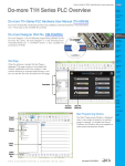
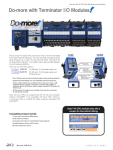
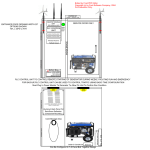
Do-more H2 Series PLC Overview
Company
Information
Systems
Overview
Programmable
Controllers
Do-more H2 Series PLC
Modules
The Do-more H2 Series PLC is the newest
technology available that makes control
applications easier to implement. It uses
proven DirectLOGIC hardware as a platform for a powerful, flexible instruction
set, with a user-friendly programming
environment. The Do-more H2 Series
PLC utilizes most of the modules that are
part of the DL205 PLC family. You simply
install a Do-more H2 Series CPU module
into a DL205 base unit. However, the
specifications of the Do-more H2 Series
PLC are very different from the DL205
PLC. This overview covers the key
features of the Do-more H2 Series PLC.
Field I/O
Software
C-more &
other HMI
Drives
Soft
Starters
Motors &
Gearbox
DL205 PLC base unit and I/O modules
Do-more H2 CPU Module
Steppers/
Servos
Motor
Controls
Proximity
Sensors
Photo
Sensors
CPU modules
Limit
Switches
The Do-more H2 Series PLC offers two
CPU modules available, H2-DM1 and
H2-DM1E, both of which must be
programmed using the Do-more Designer
programming software. You cannot use
the existing DL205 CPU modules (D2230, D2-240, D2-250(-1) and D2-260)
with Do-more Designer.
Encoders
Current
Sensors
Pressure
Sensors
Temperature
Sensors
Pushbuttons/
Lights
Process
H2-DM1
H2-DM1E
(with Ethernet)
Relays/
Timers
Comm.
Terminal
Blocks &
Wiring
Base units
The Do-more H2 Series PLC supports all
of the base units available for the DL205
PLC.
Power
Circuit
Protection
Enclosures
Tools
Pneumatics
Appendix
Product
Index
Part #
Index
Volume 14
w w w. a u t o m a t i o n d i r e c t . c o m / PA C s
Programmable Controllers
e38-1
Do-more H2 Series PLC Overview
Discrete I/O modules
The Do-more H2 Series PLC supports all
of the discrete I/O modules available for
the DL205 PLC.
Analog I/O modules
The Do-more H2 Series PLC supports all
of the analog I/O modules available for
the DL205 PLC.
Volume 14
e38-2
Programmable Controllers
1 - 80 0 - 633 - 0405
Do-more H2 Series PLC Overview
Company
Information
Systems
Overview
Programmable
Controllers
Specialty modules
The Do-more H2 Series PLC supports many of the specialty modules
available for the DL205 PLC. The following modules are supported:
Field I/O
Software
C-more &
other HMI
Drives
Soft
Starters
H2-ECOM100
H2-SERIO
H2-SERIO-4
H2-ERM
H2-CTRIO
H2-CTRIO2
Motors &
Gearbox
F2-08SIM
Steppers/
Servos
Motor
Controls
Specialty modules NOT supported
Proximity
Sensors
The following modules are NOT supported by the Do-more H2
Series PLC.
Photo
Sensors
Limit
Switches
Encoders
Current
Sensors
D2-DCM
D2-RMSM
D2-CTRINT
F2-CP128
D2-EM
D2-CM
D2-RSSS
Pressure
Sensors
Temperature
Sensors
Pushbuttons/
Lights
Process
DV-1000
Relays/
Timers
D2-HPP
Comm.
Terminal
Blocks &
Wiring
Programming Software
Power
The Do-more H2 Series PLC can only be programmed by Do-more
Designer. (DirectSOFT programming software is not compatible with Domore PLCs)
Circuit
Protection
Enclosures
Tools
Pneumatics
Appendix
Product
Index
Part #
Index
Volume 14
w w w. a u t o m a t i o n d i r e c t . c o m / PA C s
Programmable Controllers
e38-3
Do-more H2 Series PLC Overview
Module Compatibility
The following table shows which DL205 components are supported by the H2-DM1 and
H2-DM1E Do-more CPUs.
Module
Base Units
Module Compatibility Table
Status
Module
Part Number
D2-03B-1
F2-04AD-1
D2-04B-1
F2-04AD-2
D2-06B-1
F2-08AD-1
D2-09B-1
F2-08AD-2
D2-03BDC1-1
F2-04RTD
D2-04BDC1-1
F2-04THM
D2-06BDC1-1
Status
F2-02DA-1(L)
Analog I/O
Modules
D2-09BDC1-1
F2-02DA-2(L)
D2-06BDC2-1
F2-02DAS-1
D2-09BDC2-1
F2-02DAS-2
D2-08ND3
F2-08DA-1
D2-16ND3-2
F2-08DA-2
D2-32ND3
F2-4AD2DA
D2-32ND3-2
F2-8AD4DA-1
D2-08NA-1
F2-8AD4DA-2
D2-08NA-2
Local Expansion D2-CM
Modules
D2-EM
D2-16NA
Discrete I/O
Modules
Part Number
No
No
D2-04TD1
H2-ERM
D2-08TD1
H2-ERM-F
D2-08TD2
D2-RMSM
No
D2-16TD1-2
D2-RSSS
No
D2-16TD2-2
H2-ECOM100
F2-16TD1P
H2-ECOM-F
F2-16TD2P
D2-DCM
D2-32TD1
H2-EBC100
Specialty
Modules
D2-32TD2
H2-EBC-F
D2-08TA
H2-SERIO
F2-08TA
H2-SERIO-4
D2-12TA
F2-CP128
D2-04TRS
H2-CTRIO
D2-08TR
H2-CTRIO2
F2-08TR
D2-CTRINT
F2-08TRS
F2-08SIM
Programmer
Operator
Interface
D2-12TR
D2-08CDR
= Supported
No
No
No
D2-HPP
No
DV-1000
No
No = Not Supported
Volume 14
e38-4
Programmable Controllers
1 - 80 0 - 633 - 0405
Do-more H2 Series PLC Overview
Company
Information
Systems
Overview
Programmable
Controllers
Communications
The Do-more H2 Series PLC supports many communication protocols. The following table shows which CPU module
communications port or specialty module supports each protocol.
Field I/O
Software
CPU Modules
Protocols
Do-more Designer Programming
H2-DM1 / H2-DM1E
RS-232
USB Port
Serial Port
Yes
Yes
C-more &
other HMI
Specialty Modules
H2-DM1E
H2-ECOM H2-SERIO
H2-ERM
Ethernet H2-ECOM100 H2-ECOM-F H2-SERIO-4 H2-ERM-F
Port
Yes
Yes
Drives
Soft
Starters
Yes
Modbus/RTU Client (Master)
Yes
Yes
Modbus/RTU Server (Slave)
Yes
Yes
Motors &
Gearbox
Steppers/
Servos
Modbus/TCP Client (Master)
Yes
Yes
Motor
Controls
Modbus/TCP Server (Slave)
Yes
Yes
Proximity
Sensors
DirectLOGIC RX/WX Client (Master)
Yes
Yes
Yes
DirectLOGIC RX/WX Server (Slave)
Yes
Yes
Yes
Yes
Yes
Yes
Yes
K-Sequence Server (Slave)
Yes
Photo
Sensors
Limit
Switches
Yes
Encoders
DirectNET Server (Slave)
Current
Sensors
HEI Ethernet Remote I/O Master
Yes
SMTP (EMail) Client
w/Authentication
Simple Network Time Protocol
(SNTP) Client
Pressure
Sensors
Yes
Yes
Temperature
Sensors
Do-more/PEERLINK
Yes
Pushbuttons/
Lights
Do-more Time Synchronization
Protocol (Client, Server, Alternate
Client)
Yes
Do-more Logger/UDP
Yes
Process
Relays/
Timers
Comm.
Serial ad-hoc ASCII/Binary
Programatic Control
Yes
Yes
UDP ad-hoc Programmatic Control
Yes
TCP Client Programmatic Control
Yes
TCP Server Programmatic Control
Yes
Terminal
Blocks &
Wiring
Power
Circuit
Protection
Enclosures
Blank = Not Supported
Tools
Pneumatics
Appendix
Product
Index
Part #
Index
Volume 14
w w w. a u t o m a t i o n d i r e c t . c o m / PA C s
Programmable Controllers
e38-5
Do-more H2 Series PLC Overview
Do-more Designer (Part No. DM-PGMSW)
Do-more Designer is the full-featured programming software for the
Do-more PLC series. Do-more Designer is a free download from
Automationdirect.com. A CD-ROM version is also available for
purchase.
Start Page
When the software is started, the Start Page is
displayed. This page contains a Launchpad with
Projects, Applications and Links windows. It also
contains shortcuts to important help file topics and
the Do-more Simulator.
Launchpad
Help File
Shortcuts
Main Programming Window
Project
Toolbar
The Main Programming Window is displayed
when a new program is started or an existing
program is opened. It is divided into Menus,
Toolbars, and Windows that work together to
make project development as simple as
possible.
Project
Browser
Ladder
View
Ladder
Palette
Bar
Volume 14
e38-6
Programmable Controllers
1 - 80 0 - 633 - 0405
Do-more H2 Series PLC Overview
Company
Information
Systems
Overview
Programmable
Controllers
Do-more Designer Features
Do-more Designer has the following main features:
Field I/O
• Supports the Do-more PLC instruction set
• Project Browser (Window to organize the user project)
• Data View (Interface to monitor PLC data in a list)
• Trend View (Interface to monitor PLC data with trend graphs)
• PID View (Interface to monitor and tune the individual PID control loop)
• PID Overview (Interface to monitor multiple PID control loops)
• Debug View (Interface to debug the ladder programs)
Software
C-more &
other HMI
Drives
Soft
Starters
When Do-more Designer is installed on your PC, the following tools are also installed:
Motors &
Gearbox
• Do-more Simulator (Offline simulator of ladder program execution and PID control)
• Do-more Logger (Software tool to log PLC data)
• ERM Workbench (Configuration tool for the ERM modules)
• NetEdit 3 (Configuration tool for the ECOM/EBC Ethernet modules)
Steppers/
Servos
Motor
Controls
PC Requirements
Proximity
Sensors
The Do-more Designer Windows-based programming software works with Windows®
XP (Home or Professional, 32-bit), Vista (Home, Basic, Premium, 32 or 64-bit) or
Windows 7 (Home, Professional, Ultimate, 32 or 64-bit). Please check the following
requirements when choosing your PC configuration:
Photo
Sensors
Limit
Switches
• Minimum PC to PLC Connectivity, at least one of the following:
- USB Port: connects to the CPU with USB-A connector (USB-A to USB-B cable)
- RS-232 Serial Port: connects to the CPU with RJ-12 connector (RJ-12 to DB9 or RJ-12 to USB-B
serial converter cable)
- Ethernet Port: connects to the CPU (H2-DM1E) with RJ-45 10Base-T or 100Base-T (Cat5 Patch
Cable)
• Hard Disk: 100MB free disk space
• Video Display: 1024x768, 256 colors resolution (1280x720, true color recommended)
• Windows XP, 32-bit:
- 800MHz, single core CPU (2GHz, multi-core or hyperthreaded recommended)
- 512MB RAM (2GB recommended)
• Vista or Windows 7, 32 or 64-bit:
- 1GHz, single core CPU (2GHz, multi-core recommended)
- 1GB RAM (3GB recommended)
Encoders
Current
Sensors
Pressure
Sensors
Temperature
Sensors
Pushbuttons/
Lights
Process
Relays/
Timers
Comm.
Programming Cables
Terminal
Blocks &
Wiring
The Do-more H2 Series CPU module H2-DM1 has two communication ports (USB
and RS-232 serial) and the H2-DM1E has three communication ports (USB, RS-232
serial and Ethernet). You can use any of those ports for programming and monitoring.
Needed cables for these ports are listed below and can be purchased at
Automationdirect.com.
Power
Circuit
Protection
USB Cables (USB 2.0, Type A-B connectors) available:
Enclosures
• USB-CBL-AB3 (3 ft.)
• USB-CBL-AB6 (6 ft.)
• USB-CBL-AB10 (10 ft.)
• USB-CBL-AB15 (15 ft.)
Tools
Pneumatics
Appendix
RS232 Serial Cable
Product
Index
• D2-DSCBL (12 ft. 9-pin D-sub to RJ12 connector)
Ethernet Cables (Cat5e)
Part #
Index
Automationdirect.com sells many Ethernet patch cables in various colors and lengths. Please
check the Cables section in this catalog for further details.
Volume 14
w w w. a u t o m a t i o n d i r e c t . c o m / PA C s
Programmable Controllers
e38-7
Do-more H2 Series PLC Overview
Do-more PLC Instruction Set
This Instruction Set was developed specifically
for the new Do-more PLC; the ‘Instruction
Palette’ displays all available instructions.
You may see some similarities to the
DirectLOGIC PLC instruction set. However, the
instruction set for the Do-more PLC is more
advanced and intuitive. A good example is the
MATH instruction. Now, just one MATH
instruction covers all math operations and
also allows you to mix different data types in
one expression.
There are over 60 operators and functions
available with the MATH instruction.
Note: To learn more about the MATH instruction, please refer to the Do-more Designer
help topic ‘MATH – Math Expression’.
Operators
+, -, *, /, %, **, <, <=, ==, !=, >=, >, &&, ||, &, |, ^, <<, >>, >>>, -, ~, !
Funcons
ABS, ACOS, ASIN, ATAN, AVGR, COS, COUNTIFEQ, COUNTIFNE,
COUNTIFGE, COUNTIFGT, COUNTIFLE, COUNTIFLT, DEG, E, FRAC, IF,
LN, LOG, MAXR, MAX, MINR, MIN, NOW, PI, RAD, RANDINT, RANDREAL,
REF, ROUND, SIN, SQRT, STDEVR, STDEVPR, SUMIFEQ, SUMIFNE,
SUMIFGE, SUMIFGT, SUMIFLE, SUMIFLT, SUMR, TAN, TICKms,
TICKus, TOINT, TOREAL, TRUNC
Volume 14
e38-8
Programmable Controllers
1 - 80 0 - 633 - 0405
Do-more H2 Series PLC Overview
Company
Information
Systems
Overview
Programmable
Controllers
Data Types
The Do-more PLC supports the following seven primary data types:
Field I/O
• Bit (0 or 1)
• Unsigned Byte (0 to 255)
• Signed Byte (-128 to 127)
• Unsigned Word (0 to 65,535)
• Signed Word (-32,768 to 32,767)
• Signed DWord (-2,147,483,648 to 2,147,483,647)
• Real (-3.4028235E+038 to 3.4028235E+038)
Software
C-more &
other HMI
Drives
Soft
Starters
Note: As you can see, the BCD data type that is popular for the DirectLOGIC PLC is not
included in this list. However, you can use the BCDTO and TOBCD instructions if you
need to use the BCD data type with your application. Those instructions convert the data
between the BCD data type and the integer/real data types.
Motors &
Gearbox
Steppers/
Servos
Data Structure
Motor
Controls
The Do-more PLC supports data structures as additional data types. Structures use the
familiar PC programming organization of “dot notation”. All available elements of a
structure are shown in this format. The following data structures are currently available:
Proximity
Sensors
Photo
Sensors
• Timer Structure
• Counter Structure
• String Structure
• PID Structure
• Date/Time Structure
• Task Structure
• Rampsoak Structure
• Program Structure
• DeviceRef Structure
• Drum Structure
Limit
Switches
Encoders
Current
Sensors
Pressure
Sensors
The data structure is a set of data. For instance, a Timer structure (Timer Struct) has the
following set of data:
Temperature
Sensors
Pushbuttons/
Lights
• Acc (Accumulated Time, Signed DWord)
• Done (Bit)
• Zero (Bit)
• Timing (Bit)
• Reset (Bit)
Process
Relays/
Timers
When you use a timer instruction (TMR), a Timer structure is assigned to the instruction.
If you select ‘T0’, you can access the above data with dot notation. For instance, to
access the accumulated time (Acc), enter ‘T0.Acc’. To access the Done bit, enter
‘T0.Done’.
Comm.
Terminal
Blocks &
Wiring
Memory Addressing
Power
With the Do-more PLC, each memory address type has its own specific data type. Here
are some examples:
Circuit
Protection
Enclosures
• V (Unsigned Word)
• N (Signed Word)
• D (Signed DWord)
• R (Real)
Tools
Pneumatics
Appendix
If you see address ‘V123’ in the ladder program, the memory address always stores an
Unsigned Word value. With this memory addressing method, it becomes easier to read
and write the ladder programs.
Product
Index
Part #
Index
Although most of the memory addressing is decimal, the memory addresses DLX, DLY,
DLC and DLV use octal. These four memory addresses can be used to exchange data
with DirectLOGIC PLCs, which use octal memory addressing.
Volume 14
w w w. a u t o m a t i o n d i r e c t . c o m / PA C s
Programmable Controllers
e38-9
Do-more H2 Series PLC Overview
Array Addressing
The Do-more PLC supports array addressing with all memory addresses. V-memory
address must be used as the index for an array. With the Do-more PLC, the following
ladder program is valid.
Note: In this example, V0, V100, V101, V102 and V200 are indices.
Code-block, Program and Task
One Do-more project can consist of more than one ladder program. Each ladder
program is called a ‘Code-block’. The Do-more PLC supports two types of code-blocks,
Program and Task. Here are their definitions.
Program
Programs are code-blocks that run based on an event using the RUN instruction. They
can be self-terminating or never terminate. Stage programming is only supported inside
Program code-blocks.
Task
Tasks are code-blocks that are enabled and disabled using the ENTASK instruction. The
ENTASK instruction allows you to specify an interval to execute the task’s logic with a
millisecond resolution or to execute a single time on a leading edge input.
Stages
The Do-more PLC supports Stages. You can use Stages only in the Program code-blocks.
(They are not available in the Task code-blocks.) The Do-more PLC supports the following
instructions for Stage Programming1:
• SG (SG)
• JMP (Jump To Stage)2
• JMPI (Index Jump)
• SGSET (Enable Stage)
• SGRST (Disable Stage)
• SGRSTR (Disable Range of Stages)
• SGCONVRG (Converge Multiple Stages to SG)
• SGDIVRG (Jump to Multiple Stages)
1 There
is no ISG (Initial Stage) instruction for the Do-more PLC; the first stage in the
Program code-block becomes the initial stage automatically.
2 Many
asynchronous instructions can directly initiate a Jump to Stage.
Volume 14
e38-10
Programmable Controllers
1 - 80 0 - 633 - 0405
Do-more H2 Series PLC Overview
Company
Information
Systems
Overview
Programmable
Controllers
Comparison with the DL205 PLC
The following spec table shows the major differences between the
Do-more H2 Series PLC and the DL205 PLC.
Field I/O
Software
C-more &
other HMI
Do-more H2 Series PLC
DL205 PLC
Do-more PLC instruction set
DirectLOGIC PLC instruction set
Drives
262.1K
30.4K
Soft
Starters
BCD, HEX and Real
Motors &
Gearbox
Octal
Steppers/
Servos
Yes
No
Motor
Controls
Bit of Memory
Available for all memory addresses (e.g. V100.2,
D200.3)
Yes, D2-250(-1) and D2-260 only
Array Addressing
Available for all memory addresses (e.g. X[V100], Available only for V-memory addresses (e.g. P2000)
D[V200])
Math Calculation
No accumulator, the MATH instruction can support a Using accumulator or using the MATHBCD, MATHmix of different data types.
BIN or MATHR instruction for each data type.
Instruction Set
Total Memory Bytes
Default Data Type
Memory Addressing
Decimal and Real
(Data can be referred in different data types with the
‘Casting’ feature.)
Decimal mainly
(There are some octal memory addresses to
exchange data with DirectLOGIC PLCs easily.)
User-defined Memory Addresses
Number of Code Blocks
Looping
1 system program
6 system tasks
Up to 256 user programs
Up to 256 user tasks
FOR-NEXT, WHILE-WEND,
REPEAT-UNTIL
Subroutines
User Document (Nicknames, Rung
Comments…) Storing
Proximity
Sensors
1
Current
Sensors
FOR-NEXT
Pressure
Sensors
Yes
Stored in the CPU module
No (Stored on PC only)
Multiple passwords
Single password
Bumpless
Ladder program execution is paused during the
ladder program transfer in RUN mode.
Run-time Editing
Limit
Switches
Encoders
No (Use Code-blocks)
Password Protection
Photo
Sensors
Temperature
Sensors
Pushbuttons/
Lights
Process
The X, WX and WY addresses are assigned to
analog I/O channels automatically. (Manual
addressing is available also.)
Configured by ladder program
Relays/
Timers
Local Base Expansion
No
Yes (with D2-EM and D2-CM)
Comm.
Number of PID Loops
Over 2000
4 (D2-250-1), 16 (D2-260)
Terminal
Blocks &
Wiring
Included
Optional
CPU module firmware can be updated from
Do-more Designer.
Use firmware update tool
Yes, Full duplex
Yes, Half duplex
Yes
No
Yes (H2-DM1E)
No
Do-more Designer
DirectSOFT
Analog I/O Configuration
Memory Back-up Battery
Firmware Update
Built-in RS-232 Port
Built-in USB Port
Built-in Ethernet Port
Programming Software
Power
Circuit
Protection
Enclosures
Tools
Pneumatics
Appendix
Product
Index
Part #
Index
Volume 14
w w w. a u t o m a t i o n d i r e c t . c o m / PA C s
Programmable Controllers
e38-11
Dimensions and Installation
Company
Information
Systems
Overview
Understanding the installation requirements for your Do-more H2 Series PLC
system will help ensure that the components operate within their environmental
and electrical limits.
See
the Enclosures section
for an enclosure that may
be suitable for your
application
2"
50.8mm
minimum
Programmable
Controllers
Field I/O
Software
C-more &
other HMI
Plan for safety
TERM
RUN
STOP
2""
2
8
50.8mm
m
minimum
USB
PGM
PORT
This catalog should never be used as a
replacement for the user manual. The user
manual, H2-DM-M (sold separately or
downloadable online), contains important
safety information that must be followed.
The system installation should comply with
all appropriate electrical codes and standards.
RS-232
SERIAL
E
1 T
0 H
/ E
1 R
0 N
0 E
T
Drives
Soft
Starters
1.2"
30mm
minimum
Motors &
Gearbox
Steppers/
Servos
Motor
Controls
Environmental
specifications
Proximity
Sensors
The Environmental Specifications table at
the right lists specifications that apply
globally to the Do-more H2 Series PLC
system (CPUs, bases, and I/O modules).
Be sure that the system is operated within
these environmental specifications.
Base dimensions
and mounting
Use the diagrams below to make sure the
Do-more H2 Series PLC system can be
installed in your application. To ensure
proper airflow for cooling purposes,
bases must be mounted horizontally. It is
important to check these dimensions
against the conditions required for your
application. For example, it is recommended that approximately 3" of space is
left in front PLC surface for ease of access
and cable clearances. Also, check the
installation guidelines for recommended
cabinet clearances.
Photo
Sensors
Limit
Switches
Environmental Specification
Rating
Storage Temperature
Ambient Operating Temperature
Ambient Humidity
Vibration Resistance
Shock Resistance
Noise Immunity
Atmosphere
Base
3-slot
4-slot
6-slot
9-slot
12 or 16pt. I/O
Encoders
-4 F - 158 F (-20 C to 70 C)
o
o
o
o
Current
Sensors
32oF - 131oF (0oC to 55oC)
30%-95% relative humidity (non-condensing)
Pressure
Sensors
MIL STD 810C, Method 514.2
MIL STD 810C, Method 516.2
Temperature
Sensors
NEMA (ICS3-304)
No corrosive gases
A
(Base Total Width)
Pushbuttons/
Lights
B
(Mounting Hole)
C
(Component Width)
Inches
Millimeters Inches
Millimeters Inches
Millimeters
6.77”
7.99”
10.43”
14.09”
172mm
203mm
265mm
358mm
163mm
194mm
256mm
349mm
148mm
179mm
241mm
334mm
6.41”
7.63”
10.07”
13.74”
5.8”
7.04”
9.48”
13.14”
A
3.62”
(92mm)
2.95”
(75mm)
C
4 or 8pt. I/O
TERM
ZL-D24-CBL40-X
ZipLink cable
RUN
STOP
USB
PGM
PORT
RS-232
SERIAL
TERM
E
1 T
0 H
/ E
1 R
0 N
0 E
T
ZL-D24-CBL40
ZipLink cable
Terminal
Blocks &
Wiring
Power
Enclosures
Pneumatics
7.91"
(201mm)
D2-DSCBL-1
Approximate
Dimension
5.85”
(148mm)
3.62”
(92mm)
Volume 14
Programmable Controllers
Appendix
Product
Index
Airflow
Ai
fl
w w w. a u t o m a t i o n d i r e c t . c o m / PA C s
Comm.
Tools
B
4.76"
(121mm)
RUN
USB
PGM
PORT
RS-232
SERIAL
H2-DM1E
2.99”
(76mm)
E
1 T
0 H
/ E
1 R
0 N
0 E
T
STOP
OK
Relays/
Timers
Circuit
Protection
H2-DM1E
3.54”
90mm)
Process
e38-33
Part #
Index