1
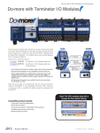
Do-more with Terminator I/O Modules
The Do-more T1H series CPUs are the new “brains” for the time-tested
Terminator Field I/O hardware. The chip set inside includes the exact
same processor as is used in the Do-more H2 series. The feature set for
these CPUs is identical. Your ladder code is even portable between the
two hardware platforms.
T1H-DM1
T1H-DM1E
There are two T1H CPU options:
$ (1) USB port, (1) full-duplex serial port
T1H-DM1 $585.00
T1H-DM1E $745.00
(1) USB port, (1) full-duplex serial port,
(1) Ethernet port
• Over 1M bytes total memory (includes program, data and documentation)
• Program/monitor/debug over any embedded communication port.
• Power supply modules are available for AC or DC power input. Add
additional power supplies in-line with Terminator I/O modules as
needed to power the modules AND to supply isolated 24 VDC power for
field devices.
• 28 Terminator option analog and high-speed counter modules are
available, from discrete and analog to high-speed counting
Note: Do-more CPUs are programmed with the new Do-more Designer
software. DirectSOFT, and ladder programs developed with DirectSOFT,
are not compatible with these CPUs.
Both T1H CPU modules ship with a
coupon for free online training.
Compatible products include:
• C-more and C-more Micro HMI products
• Stride® Ethernet switches
• Connectivity to SureServo® and SureStep® motion products
• Variable frequency drives and AC motors
• Discrete and process sensors
Volume 14
e44-2
Programmable Controllers
1 - 80 0 - 633 - 0405
Pick Your Pieces and Drop ‘em In
Company
Information
Systems
Overview
Programmable
Controllers
Two sizes of terminal bases
accommodate
all I/O modules
Field I/O
Software
• Half-size bases for modules with up to
8 points for only $55.00 (T1K-08B, T1K-08B-1)
• Full size bases for modules with up to
16 points for only $69.00 (T1K-16B, T1K-16B-1)
• Triple-stack terminal blocks standard,
easy to connect multi-wire devices
• Same bases for all I/O modules AC, DC, and analog
• Screw and spring clamp terminals
Power supplies - freedom
of choice, freedom to
expand
• DC power supplies for $111.00 (T1K-01DC),
AC versions only $116.00 (T1K-01AC)
• AC supplies include 24 VDC auxiliary
supply for convenient field device
wiring
• Need more power for high current
devices or modules? Just add another
power supply before the next modules in
the system!
Analog modules
at a super low price
per channel
8-channel I/O
16-channel I/O
Four types of 8-channel I/O
Four types of 16-channel I/O
Two types of combination I/O
Thermocouple and RTD modules
• 8-channel input modules
starting at $290.00
• 16-channel output modules
starting at $591.00
• 0-20mA/4-20 mA and unipolar/bipolar
voltage models available
• 14-channel thermocouple module
only $519.00 (T1F-14THM)
C-more &
other HMI
Drives
Soft
Starters
Motors &
Gearbox
Local expansion - up to two
additional rows
• Full backplane expansion through cables
• Connect up to 16 modules across three
total rows by plugging expansion cables
from the side of one module to the side
of the next. The system automatically
recognizes the I/O.
• Optional cable that includes 24 VDC pins
maximizes your power supply capability.
Steppers/
Servos
Motor
Controls
Proximity
Sensors
Photo
Sensors
Limit
Switches
Encoders
Current
Sensors
Discrete I/O with the
features you need
• 8-point input modules starting
at only $69.00
• 16-point I/O starting at
only $119.00
• All DC input modules are
sink/source jumper
configurable
• Diagnostic LEDs for blown
fuse and 24 VDC power on
applicable modules
Pressure
Sensors
Temperature
Sensors
8-point I/O
Pushbuttons/
Lights
Process
Relays/
Timers
16-point I/O
Comm.
Easy-access
replaceable fuses on
all discrete output
modules
Specialty module
• Counter module with pulse out,
$311.00 (T1H-CTRIO)
Terminal
Blocks &
Wiring
Power
Circuit
Protection
Enclosures
Tools
Pneumatics
DL205 I/O
Safety
• Connect DL205 Ethernet-based remote I/O drops
to the optional Ethernet port on the -T1H-DM1E CPU
• Dozens of I/O option modules supported,
including high-density discrete modules
Appendix
Product
Index
Part #
Index
Volume 14
w w w. a u to m a t i o n d i re c t . c o m / d o - m o re - p l c s
Programmable Controllers
e44-3
Do-more with High-speed I/O
High-speed operations
High-speed timing
The T1H-CTRIO module is capable of a wide variety of highspeed input and output operations. Many of these operations
take place on board the module, and are independent of the
scan time of your PLC. With flexible 4-channel input and
separate output channel design, these modules can satisfy
high-speed counting, timing, and pulse catch operations,
along with high-speed discrete output or several profile
choices of pulse output operations. Not all combinations of
input functions and output functions are possible within the
resources of the module, but these examples are typical of the
applications for these modules.
The T1H-CTRIO module can be configured for timing functions
based on both count or rate. Using a common configuration of
a proximity switch sensing the teeth on a gear, the module is able
to calculate the velocity of the gear based on the rate at which it
receives counts. This value can be scaled within the module to
the engineering units required for the application.
$
311
PLC with CTRIO module
Gear
High Speed
Counter Moduel
Counting & timing up to
100 kHz:
T1H-CTRIO $311.00
Four 100 kHz inputs, and
two 20-25 kHz pulse train
outputs
High-speed
edge timing
High-speed counting
Inputs Supported:
•
•
•
•
•
Counter
Quad Counter
Pulse Catch
Edge Timer
Dual Edge Timer
Outputs Supported:
• Pulse train - used for servo/stepper motor control.
Configurable for CW/CCW or step and direction.
• Discrete outputs - assigned to Counter/Timer input
functions
• Raw output - outputs controlled directly from the CPU
interface program
The T1H-CTRIO module can be configured for counting functions via the use of an encoder input. Up to two quadrature
encoders per CTRIO module are available with connections for
external reset, capture and inhibit signals. In a simple cut-tolength application as shown below, the encoder provides an
input position reference for the material to the module. The
module's high-speed outputs are wired to the cutting device and
to the clutch and/or braking device. When the count from the
encoder is equal to a pre-programmed setpoint within the
module, the high-speed outputs are activated to stop and cut the
material to a repeatable fixed length. Additionally, the
clutch/brake signal can be used as an inhibit signal so counts are
not accumulated while the material is being cut.
High-speed cut-to-length application
PLC with CTRIO module
Motor
Interface
Improved to Do-more!
All your CTRIO configuration is done through the Do-more
Designer Software - no more separate software “workbench”.
And if you should need to replace a high-speed module, all
the setup parameters and profiles are stored in the CPU and
are automatically loaded and ready to go when the system
powers up.
Motor
control
lines
Gearbox, clutch and
brake interface
CTRIO
high-speed
output
Encoder
Cutter assembly
Material to be
cut to length
Volume 14
e44-4
Programmable Controllers
1 - 80 0 - 633 - 0405
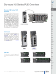
Do-more T1H Series PLC Overview
Company
Information
Systems
Overview
Programmable
Controllers
Do-more T1H Series
PLC
Field I/O
The T1H Series PLC takes the modular
and space-saving package of our
Terminator I/O line and converts it into a
stand-alone control system. Using Domore Designer as a foundation, the T1H
Series PLC system provides a powerful,
flexible instruction set, inside a user
friendly programming environment.
Software
C-more &
other HMI
Drives
Soft
Starters
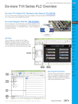
Do-more T1H PLC System with T1H-DM1E CPU Module
Motors &
Gearbox
Steppers/
Servos
Motor
Controls
T1H-DM1
Proximity
Sensors
CPU modules
The Do-more T1H Series PLC offers two
CPU modules, T1H-DM1 and T1HDM1E, both of which must be
programmed using the Do-more Designer
programming software version 1.2 or
later.
T1H-DM1E
(with Ethernet)
Photo
Sensors
Limit
Switches
Encoders
Current
Sensors
Pressure
Sensors
Temperature
Sensors
Pushbuttons/
Lights
Process
Relays/
Timers
Comm.
Terminal
Blocks &
Wiring
Base units
Power
The Do-more T1H Series PLC supports all
of the base units available for the
Terminator I/O line.
Circuit
Protection
Enclosures
Tools
Pneumatics
Appendix
Product
Index
Part #
Index
Volume 14
w w w. a u to m a t i o n d i re c t . c o m / d o - m o re - p l c s
Programmable Controllers
e44-5
Do-more T1H Series PLC Overview
Discrete I/O modules
The Do-more T1H Series PLC supports all
of the discrete I/O modules available in
the Terminator I/O product line.
Analog I/O modules
The Do-more T1H Series PLC supports all
of the analog I/O modules available in
the Terminator I/O product line.
Specialty module
The Do-more T1H Series PLC supports
the T1H-CTRIO High-Speed Counter I/O
module that is available in the Terminator
I/O product line.
T1H-CTRIO
Programming Software
The Do-more T1H Series PLC can only be
programmed by Do-more Designer
version 1.2 or later.
1.2
Volume 14
e44-6
Programmable Controllers
1 - 80 0 - 633 - 0405
Do-more T1H Series PLC Overview
Company
Information
Systems
Overview
Programmable
Controllers
Module Compatibility
The following table shows which Terminator I/O product line components are supported
by the T1H-DM1 and T1H-DM1E Do-more CPUs.
Field I/O
Software
Module
Base Units
Module Compatibility Table
Status
Module
Part Number
Part Number
T1K-08B
T1F-08AD-1
T1K-08B-1
T1F-08AD-2
T1K-16B
T1F-16AD-1
T1K-16B-1
T1F-16AD-2
T1K-08ND3
T1F-14THM
T1K-16ND3
T1K-08NA-1
Discrete I/O
Modules
C-more &
other HMI
Analog I/O
Modules
Status
Drives
Soft
Starters
Motors &
Gearbox
Steppers/
Servos
T1F-16RTD
T1F-08DA-1
T1K-16NA-1
T1F-08DA-2
T1K-08TD1
T1F-16DA-1
T1K-16TD1
T1F-16DA-2
T1K-08TD2-1
T1F-8AD4DA-1
T1K-16TD2-1
T1F-8AD4DA-2
Motor
Controls
Proximity
Sensors
Photo
Sensors
Limit
Switches
T1H-08TDS
T1K-08TA
Encoders
T1K-16TA
T1K-08TAS
Specialty
Module
Current
Sensors
T1H-CTRIO
T1K-08TR
Pressure
Sensors
T1K-16TR
T1K-08TRS
Temperature
Sensors
= Supported
Pushbuttons/
Lights
Process
Relays/
Timers
Comm.
Terminal
Blocks &
Wiring
Power
Circuit
Protection
Enclosures
Tools
Pneumatics
Appendix
Product
Index
Part #
Index
Volume 14
w w w. a u to m a t i o n d i re c t . c o m / d o - m o re - p l c s
Programmable Controllers
e44-7
Do-more T1H Series PLC Overview
Communications
The Do-more T1H Series PLC supports many communication protocols. The following table shows which CPU module
communications port supports each protocol.
CPU Modules
T1H-DM1 / T1H-DM1E
Protocols
Do-more Designer Programming
T1H-DM1E
USB Port
RS-232
Serial Port
Ethernet
Port
Yes
Yes
Yes
Modbus/RTU Client (Master)
Yes
Modbus/RTU Server (Slave)
Yes
Modbus/TCP Client (Master)
Yes
Modbus/TCP Server (Slave)
Yes
DirectLOGIC RX/WX Client (Master)
Yes
DirectLOGIC RX/WX Server (Slave)
Yes
K-Sequence Server (Slave)
Yes
DirectNET Server (Slave)
HEI Ethernet I/O Master
Yes
SMTP (EMail) Client w/Authentication
Yes
Simple Network Time Protocol (SNTP) Client
Yes
Do-more/PEERLINK
Yes
Do-more Time Synchronization Protocol (Client, Server,
Alternate Client)
Yes
Do-more Logger/UDP
Yes
Serial ad-hoc ASCII/Binary Programatic Control
Yes
UDP ad-hoc Programmatic Control
Yes
TCP Client Programmatic Control
Yes
TCP Server Programmatic Control
Yes
Blank = Not Supported
Volume 14
e44-8
Programmable Controllers
1 - 80 0 - 633 - 0405
Do-more T1H Series PLC Overview
Company
Information
Systems
Overview
Programmable
Controllers
Do-more T1H Series PLC Hardware User Manual (T1H-DM-M)
Do-more T1H Series PLC Hardware User Manual is available as a free download from
Automationdirect.com. A hard copy is also available for purchase.
Field I/O
Software
Do-more Designer (Part No. DM-PGMSW)
C-more &
other HMI
Do-more Designer is the full-featured programming software for the
Do-more PLC series. Do-more Designer is a free download from
Automationdirect.com. A CD-ROM version is also available for
purchase.
Drives
1.2
Soft
Starters
Motors &
Gearbox
Steppers/
Servos
Motor
Controls
Start Page
When the software is started, the Start Page is
displayed. This page contains a Launchpad with
Projects, Applications and Links windows. It also
contains shortcuts to important help file topics, and
you can start the Do-more Simulator from this page.
Proximity
Sensors
Photo
Sensors
Limit
Switches
Encoders
Current
Sensors
Launchpad
Pressure
Sensors
Temperature
Sensors
Pushbuttons/
Lights
Process
Do-more
Simulator
Help File
Shortcuts
Relays/
Timers
Main Programming Window
Project
Toolbar
The Main Programming Window is displayed
when a new project is started or an existing
project is opened. It is divided into Menus,
Toolbars, and Windows that work together to
make project development simple.
Project
Browser
Comm.
Terminal
Blocks &
Wiring
Power
Circuit
Protection
Enclosures
Tools
Pneumatics
Ladder
View
Appendix
Product
Index
Ladder
Palette
Bar
Part #
Index
Volume 14
w w w. a u to m a t i o n d i re c t . c o m / d o - m o re - p l c s
Programmable Controllers
e44-9
Do-more T1H Series PLC Overview
Do-more Designer Features
Do-more Designer has the following main features:
• Supports the Do-more PLC instruction set
• Project Browser (Window to organize the user project)
• Data View (Interface to monitor and edit PLC data in a list)
• Trend View (Interface to monitor PLC data with trend graphs)
• PID View (Interface to monitor and tune the individual PID control loop)
• PID Overview (Interface to monitor multiple PID control loops)
• Debug View (Interface to debug the ladder programs)
When Do-more Designer is installed on your PC, the following tools are also installed:
• Do-more Simulator (Offline simulator of ladder program execution and PID control)
• Do-more Logger (Software tool to log PLC data)
• ERM Workbench (Configuration tool for the ERM modules)
• NetEdit 3 (Configuration tool for the ECOM/EBC Ethernet modules)
PC Requirements
The Do-more Designer Windows-based programming software works with Windows®
XP (Home or Professional, 32-bit), Vista (Home, Basic, Premium, 32 or 64-bit),
Windows 7 (Home, Professional, Ultimate, 32 or 64-bit) or Windows 8 (Home,
Professional, Enterprise 32 or 64-bit; Windows 8 RT edition is NOT supported).
Please check the following requirements when choosing your PC configuration:
• Minimum PC to PLC Connectivity, at least one of the following:
- USB Port: connects to the CPU with USB-A connector (USB-A to USB-B cable)
- RS-232 Serial Port: connects to the CPU with RJ-12 connector (RJ-12 to DB9 or RJ-12 to USB-B
serial converter cable)
- Ethernet Port: connects to the CPU (T1H-DM1E) with RJ-45 10Base-T or 100Base-T (Cat5 Patch
Cable)
• Hard Disk: 100MB free disk space
• Video Display: 1024x768, 256 colors resolution (1280x720, true color recommended)
• Windows XP, 32-bit:
- 800MHz, single core CPU (2GHz, multi-core or hyperthreaded recommended)
- 512MB RAM (2GB recommended)
• Vista or Windows 7 or Windows 8, 32 or 64-bit:
- 1GHz, single core CPU (2GHz, multi-core recommended)
- 1GB RAM (3GB recommended)
Programming Cables
The Do-more T1H Series CPU module T1H-DM1 has two communication ports (USB
and RS-232 Serial) and the T1H-DM1E has three communication ports (USB, RS-232
Serial and Ethernet). You can use any of those ports for programming and monitoring.
Cables for these ports are listed below and can be purchased at Automationdirect.com.
USB Cables (USB 2.0, Type A-B connectors):
• USB-CBL-AB3 (3 ft.)
• USB-CBL-AB6 (6 ft.)
• USB-CBL-AB10 (10 ft.)
• USB-CBL-AB15 (15 ft.)
RS232 Serial Cable
• D2-DSCBL (12 ft. 9-pin D-sub to RJ12 connector)
Ethernet Cables (Cat5e)
Automationdirect.com sells many Ethernet patch cables in various colors and lengths. Please
check the Cables section in this catalog for further details.
Volume 14
e44-10
Programmable Controllers
1 - 80 0 - 633 - 0405
Do-more T1H Series PLC Overview
Company
Information
Systems
Overview
Programmable
Controllers
Do-more PLC Instruction Set
This Instruction Set was developed specifically
for the new Do-more PLC series; the
‘Instruction Palette’ displays all available
instructions.
Field I/O
Software
C-more &
other HMI
Drives
Soft
Starters
Motors &
Gearbox
Steppers/
Servos
Motor
Controls
Proximity
Sensors
Photo
Sensors
Limit
Switches
Encoders
Current
Sensors
Pressure
Sensors
Temperature
Sensors
You may see some similarities to the
DirectLOGIC PLC instruction set. However, the
instruction set for the Do-more PLC is more
advanced and intuitive. A good example is the
MATH instruction. Now, just one MATH
instruction covers all math operations and
also allows you to mix different data types in
one expression.
There are over 60 operators and functions
available with the MATH instruction.
Note: To learn more about the MATH instruction, please refer to the Do-more Designer
help topic ‘MATH – Calculate Expression’.
Pushbuttons/
Lights
Process
Relays/
Timers
Comm.
Terminal
Blocks &
Wiring
Operators
+, -, *, /, %, **, <, <=, ==, !=, >=, >, &&, ||, &, |, ^, <<, >>, >>>, -, ~, !
Power
Funcons
Circuit
Protection
ABS, ACOS, ASIN, ATAN, AVGR, COS, COUNTIFEQ, COUNTIFNE,
COUNTIFGE, COUNTIFGT, COUNTIFLE, COUNTIFLT, DEG, E, FRAC, IF,
LN, LOG, MAXR, MAX, MINR, MIN, NOW, PI, RAD, RANDINT, RANDREAL,
REF, ROUND, SIN, SQRT, STDEVR, STDEVPR, SUMIFEQ, SUMIFNE,
SUMIFGE, SUMIFGT, SUMIFLE, SUMIFLT, SUMR, TAN, TICKms,
TICKus, TOINT, TOREAL, TRUNC
Enclosures
Tools
Pneumatics
Appendix
Product
Index
Part #
Index
Volume 14
w w w. a u to m a t i o n d i re c t . c o m / d o - m o re - p l c s
Programmable Controllers
e44-11
Do-more T1H Series PLC Overview
Data Types
The Do-more PLC supports the following seven primary data types:
• Bit (0 or 1)
• Unsigned Byte (0 to 255)
• Signed Byte (-128 to 127)
• Unsigned Word (0 to 65,535)
• Signed Word (-32,768 to 32,767)
• Signed DWord (-2,147,483,648 to 2,147,483,647)
• Real (-3.4028235E+038 to 3.4028235E+038)
Data Structures
The Do-more PLC supports data structures as additional data types. Structures use the
familiar PC programming organization of “dot notation”. All available elements of a
structure are shown in this format. The following data structures are currently available:
• Timer Structure
• Counter Structure
• String Structure
• PID Structure
• Date/Time Structure
• Task Structure
• Rampsoak Structure
• Program Structure
• DeviceRef Structure
• Drum Structure
• Stream Structure
• SIM_Process Structure
• Server Structure
• Peerlink Structure
• I/O_Master Structure
• Eth_IO_Master Structure
• GS Drive Structure
• Packet Structure
The data structure is a set of data. For instance, a Timer structure (Timer Struct) has the
following set of data:
• Acc (Accumulated Time, Signed DWord)
• Done (Bit)
• Zero (Bit)
• Timing (Bit)
• Reset (Bit)
When you use a timer instruction (TMR), a Timer structure is assigned to the instruction.
If you select ‘T0’, you can access the above data with dot notation. For instance, to
access the accumulated time (Acc), enter ‘T0.Acc’. To access the Done bit, enter
‘T0.Done’.
Memory Addressing
With the Do-more PLC, each memory address type has its own specific data type. Here
are some examples:
• V (Unsigned Word)
• N (Signed Word)
• D (Signed DWord)
• R (Real)
If you see address ‘V123’ in the ladder program, the memory address always stores an
Unsigned Word value. With this memory addressing method, it becomes easier to read
and write the ladder programs.
Although most of the memory addressing is decimal, the memory addresses DLX, DLY,
DLC and DLV use octal. These four memory address types can be used to exchange data
with DirectLOGIC PLCs, which use octal memory addressing.
Volume 14
e44-12
Programmable Controllers
1 - 80 0 - 633 - 0405
Do-more T1H Series PLC Overview
Company
Information
Systems
Overview
Programmable
Controllers
Array Addressing
The Do-more PLC supports one-dimensional array addressing with all memory
addresses. A V-memory address must be used as the index for an array. With the
Do-more PLC, the following ladder program is valid.
Field I/O
Software
C-more &
other HMI
Drives
Soft
Starters
Motors &
Gearbox
Note: In this example, V0, V100, V101, V102 and V200 are indices.
Steppers/
Servos
Code-block, Program and Task
Motor
Controls
One Do-more project can consist of more than one ladder program. Each ladder
program is called a ‘Code-block’. The Do-more PLC supports two types of code-blocks,
Program and Task:
Proximity
Sensors
Program
Photo
Sensors
Programs are code-blocks that run based on an event using the RUN instruction. They
can be self-terminating or never terminate. Stage programming is only supported inside
Program code-blocks.
Limit
Switches
Task
Encoders
Tasks are code-blocks that are enabled and disabled using the ENTASK instruction. The
ENTASK instruction allows you to specify an interval to execute the task’s logic with a
millisecond resolution or to execute a single time on a leading edge input.
Current
Sensors
Pressure
Sensors
Temperature
Sensors
Stages
The Do-more PLC supports Stages. You can use Stages only in the Program code-blocks.
(They are not available in the Task code-blocks.) The Do-more PLC supports the following
instructions for Stage Programming1:
Pushbuttons/
Lights
Process
Relays/
Timers
• SG (Stage)
• JMP (Jump To Stage)2
• JMPI (Index Jump)
• SGSET (Enable Stage)
• SGRST (Disable Stage)
• SGRSTR (Disable Range of Stages)
• SGCONVRG (Converge Multiple Stages to SG)
• SGDIVRG (Jump to Multiple Stages)
Comm.
Terminal
Blocks &
Wiring
Power
1 There is no ISG (Initial Stage) instruction for the Do-more PLC; the first stage in the Program codeblock becomes the initial stage automatically.
Circuit
Protection
2 Many asynchronous instructions can directly initiate a Jump to Stage.
Enclosures
Tools
Pneumatics
Appendix
Product
Index
Part #
Index
Volume 14
w w w. a u to m a t i o n d i re c t . c o m / d o - m o re - p l c s
Programmable Controllers
e44-13
Do-more T1H Series PLC System
Specifications
General Specifications
General Specifications
Ambient Operating Temperature
32°F to 131°F (0°C to 55°C)
Storage Temperature
-4°F to 158°F (-20°C to 70°C)
Ambient Humidity
5% to 95% (Non-condensing)
Atmosphere
No corrosive gases. The level of environmental
pollution = 2 (UL 840)
Vibration Resistance
MIL STD 810C, Method 514.2
Shock Resistance
MIL STD 810C, Method 516.2
Voltage Withstand (Dielectric)
1500 VAC, 1 minute
Insulation Resistance
500 VDC, 10 M⏲
Noise Immunity
NEMA ICS3-304
Impulse noise 1μs, 1000 V
FCC class A
RFI (144 MHz, 430 MHz 10 W, 10 cm)
Agency Approvals
UL E185989, CE, FCC class A, NEC Class 1 Division 2
Volume 14
e44-14
Programmable Controllers
1 - 80 0 - 633 - 0405
Do-more T1H Series PLC System
Specifications
Module Placement and
I/O Usage Tables
There are no I/O module placement
restrictions with the Do-more T1H Series
PLC family. In general, any mix of up to 16
analog and discrete I/O module types can
be used in any local or Ethernet I/O base.
Specialty modules can also be used in any
local or Ethernet I/O base. Reference the
Module Placement Restrictions table to the
right for the Do-more T1H Series PLC.
Company
Information
Systems
Overview
Programmable
Controllers
Module Placement Restrictions
Module/Unit
Local CPU Base
CPUs
Discrete I/O
Analog I/O
CPU slot only
✓
✓
Ethernet I/O Base
Software
Base Controller
T1H-EBC100
Specialty Module
T1H-CTRIO
✓
✓
✓
C-more &
other HMI
CPU slot only
Drives
Soft
Starters
✓
Motors &
Gearbox
Steppers/
Servos
Analog I/O in the Ethernet I/O
bases
When using an analog module in an
Ethernet I/O base, the analog update time
to the CPU will be asynchronous to the
scan time. Critical analog I/O should be
located in the local base.
Motor
Controls
The table to the right indicates the number
of I/O points consumed by each module.
These X (discrete input), Y (discrete
output), WX (analog input) and WY
(analog output) addresses are automatically assigned by Do-more Designer.
Proximity
Sensors
I/O Module Point Usage
DC INPUT
T1K-08ND3
T1K-16ND3
8X
16 X
AC INPUT
I/O point usage
Field I/O
T1K-08NA-1
T1K-16NA-1
T1H-CTRIO
8Y
16 Y
8Y
None
8Y
16 Y
8Y
16 Y
8Y
8Y
16 Y
8Y
Photo
Sensors
Limit
Switches
Encoders
Current
Sensors
ANALOG
AC OUTPUT
T1K-08TA
T1K-16TA
T1K-08TAS
SPECIALTY MODULES
T1K-08TR
T1K-16TR
T1K-08TRS
8X
16 X
DC OUTPUT
T1K-08TD1
T1K-16TD1
T1K-08TD2-1
T1K-16TD2-1
T1H-08TDS
RELAY OUTPUT
T1F-08AD-1
T1F-08AD-2
T1F-16AD-1
T1F-16AD-2
T1F-16RTD
T1F-14THM
T1F-08DA-1
T1F-08DA-2
T1F-16DA-1
T1F-16DA-2
T1F-8AD4DA-1
T1F-8AD4DA-2
8 X, 8 WX
8 X, 8 WX
16 X, 16 WX
16 X, 16 WX
16 X, 16 WX
16 X, 16 WX
8 Y, 8 WY
8 Y, 8 WY
8 Y, 16 WY
8 Y, 16 WY
8 X, 8 WX/8 Y, 4 WY
8 X, 8 WX/8 Y, 4 WY
Pressure
Sensors
Temperature
Sensors
Pushbuttons/
Lights
Process
Relays/
Timers
Comm.
Terminal
Blocks &
Wiring
Power
Circuit
Protection
Enclosures
Tools
Pneumatics
Appendix
Product
Index
Part #
Index
Volume 14
w w w. a u to m a t i o n d i re c t . c o m / d o - m o re - p l c s
Programmable Controllers
e44-15
Do-more T1H Series PLC System
Specifications
Power supplies
Power requirements
The T1H Series PLC offers two power
supply options: AC or DC. More than one
power supply can be installed in a T1H
series PLC system with each power supply
positioned to the left of the modules they
supply power to.
Module
5VDC 24VDC
CPU Modules
DC Output Modules
200
0
T1F-08AD-1
75
50*
T1H-DM1E
275
0
T1K-08TD1
100
200*
T1F-08AD-2
75
50*
T1K-16TD1
200
400*
T1F-16AD-1
75
50*
T1K-08TD2-1
100
0
T1F-16AD-2
75
50*
T1K-16TD2-1
200
0
T1F-14THM
60
70*
T1F-16RTD
150
0
300
0
T1K-08ND3
35
0
AC Output Modules
T1K-16ND3
70
0
T1K-08TA
250
0
Analog Output Modules
AC Input Modules
T1K-16TA
450
0
T1F-08DA-1
75
150*
T1K-08NA-1
35
0
T1K-08TAS
300
0
T1F-08DA-2
75
150*
T1K-16NA-1
70
0
Relay Output Modules
T1F-16DA-1
75
150*
T1K-08TR
350
0
T1F-16DA-2
75
150*
T1K-16TR
700
0
Combination Analog Modules
T1K-08TRS
400
0
T1F-8AD4DA-1
75
60*
T1F-8AD4DA-2
75
70*
Specialty Module
T1H-CTRIO
50/60 Hz
N/A
Maximum Power
50 VA
30 W
Max. Inrush Current
20 A
10 A
Insulation
Resistance
> 10 M⏲ @ 500 VDC
Voltage Withstand
1 min. @ 1500 VAC between
primary, secondary and field
ground
Voltage
5.25 VDC
Ripple
5% max.
5% max.
Voltage
24 VDC
N/A
mA max.
24VDC Current Rating 500
(see the table N/A
PWR
below)
10% max.
N/A
Fuse 1 (primary), not replaceable
MVSTBW
MVSTBW
Replacement
2.5/4-ST-5.08 2.5/6-ST-5.08
Terminal Block
BK
BK
(Phoenix Contact)
0
* Use either internal or external source
for 24VDC
Calculating the power budget
To calculate the power budget, read the
available power (current rating) from the
Power Supply Specifications table and
subtract the power consumed by each
module to the right of the power supply.
Do not include modules to the right of an
additional power supply.
5.25 VDC
mA max
5VDC Current Rating 2000
(see the table 2000 mA max
PWR
below)
Ripple
400
* Use either internal or external source
for 24VDC
Input Voltage Range 110/220 VAC 12/24 VDC
Input Frequency
Analog Input Modules
T1H-08TDS
T1K-01DC
<--->
T1K-01AC
<--->
Power Supply
Specifications
5VDC 24VDC
0
DC Input Modules
Power supply
specifications
Module
250
T1H-EBC100
T1K-01DC
5VDC 24VDC
T1H-DM1
Interface Module
T1K-01AC
Module
Adding additional
power supplies
Each power supply furnishes power only
to the modules to its right. Inserting a
second power supply closes the power
loop for the power supply to the left, while
also powering the modules to its right.
Perform a power budget calculation for
each power supply in the system.
Power Budget Example
Module
5VDC
24VDC
T1K-01AC
+2000 mA
+300 mA
T1H-DM1E
-275 mA
-0 mA
T1K-16ND3
-70 mA
-0 mA
T1K-16TD2-1
-200 mA
-0 mA
T1F-08AD-1
-75 mA
-50 mA
Remaining
+1380 mA
+250 mA
Accessories available for
Terminator I/O are listed in the
Terminator Field I/O section of the
Price List
T1H-DM1E
T1K-01AC Current Output
5VDC PWR
2000 mA
1500 mA
24VDC PWR
300 mA
500 mA
TERM
RUN
I/O
ERR
RUN
STOP
USB
TX
RX
USB
PGM
PORT
Note: 500 mA @ 24VDC can be achieved by lowering the
5 VDC from 2000 mA to 1500 mA.
This power supply powers the CPU module and the next two
I/O modules
Volume 14
e44-16
Programmable Controllers
This power supply powers these three I/O
modules
1 - 80 0 - 633 - 0405
CPU Modules
Company
Information
Systems
Overview
Specifications
Feature
Total Memory (bytes)
Ladder Memory (instruction words)
V-Memory (words)
Non-volatile V Memory (words)
D-memory (DWORDs)
Non-volatile D Memory (DWORDs)
R-memory (REAL DWORDs)
Non-volatile R Memory (REAL DWORDs)
Boolean execution
Stage Programming
Number of Stages
Handheld Programmer
Programming Software for Windows
Built-In communications ports
T1H-DM1
<--->
Program Memory
Total I/O points available
262,144 bytes
65,536 instruction words
Configurable up to 65536 (4096 default)
Configurable up to 65536 (4096 default)
Configurable up to 65536 (4096 default)
Configurable up to 65536 (4096 default)
Configurable up to 65536 (4096 default)
Configurable up to 65536 (4096 default)
50 uSec
Yes
128 per Program code-block; number of code-blocks configurable to memory
limit
No
FREE Do-more Designer version 1.2 or newer
USB, RS-232,
USB, RS-232
Ethernet (10/100 Base-T)
Flash ROM
X, Y, each configurable up to 65536 (2048 default); WX, WY (analog in/out)
each configurable up to 65536 (256 default)
Max Number of Local I/O Modules
Local I/O points available
Ethernet I/O Discrete points
Ethernet I/O Analog I/O Channels
Max Number of Ethernet slaves per PLC
I/O points on Ethernet I/O
Discrete I/O Module Point Density
Number of instructions available
T1H-DM1E <--->
Control relays
Special relays (system defined)
Special registers (system defined)
Timers
Counters
System Date/Time structures
User Date/Time structures
ASCII String/Byte buffer structures
Modbus Client memory
DL Classic Client memory
Immediate I/O
Interrupt input (hardware / timed)
Subroutines
Drum Timers
Table Instructions
Loops
Math
ASCII
PID Loop Control, Built In
Time of Day Clock/Calendar
Run Time Edits
Supports True Force
Internal Diagnostics
Password security
System error log
User error log
Battery backup
T1H-DM1E
T1H-DM1
Field I/O
Software
C-more &
other HMI
Drives
Soft
Starters
Motors &
Gearbox
Steppers/
Servos
Motor
Controls
Proximity
Sensors
16
Photo
Sensors
256
131,072
Limit
Switches
32,768
16
Encoders
32,768
8/16
>160
>170
Configurable up to 65536 (2048 default)
1024
512
Configurable up to 65536 (256 default)
Configurable up to 65536 (256 default)
8
Configurable up to 65536 (32 default)
Current
Sensors
Pressure
Sensors
Temperature
Sensors
Pushbuttons/
Lights
Process
Configurable up to memory limit (192 default)
Yes, configurable up to memory limit, default 1024 input bits, 1024 coil bits,
2048 input registers, 2048 holding registers
Relays/
Timers
Up to memory limit, default 512 X, 512 Y, 512 C, 2048 V
Comm.
No
No
Program and Task code-blocks, up to memory limit
Yes, up to memory limit
Yes
FOR/NEXT, WHILE/WEND, REPEAT/UNTIL loops
>60 operators and functions: Integer, Floating Point, Trigonometric, Statistical,
Logical, Bitwise, Timing
Yes, IN/OUT, Serial, Ethernet TCP and UDP; 11 output script commands
Yes, configurable to memory limit (over 2,000)
Yes
Yes
Yes
Yes
Multi-user, credentialed, session-based security
Yes
Yes
Yes (Battery included)
Volume 14
w w w. a u to m a t i o n d i re c t . c o m / d o - m o re - p l c s
Programmable
Controllers
Programmable Controllers
e44-17
Terminal
Blocks &
Wiring
Power
Circuit
Protection
Enclosures
Tools
Pneumatics
Appendix
Product
Index
Part #
Index
CPU Modules
T1H-DM1
T1H-DM1E
USB 2.0 Port (Type B)
- Programming
RS 232 Serial Port (RJ12)
- Programming
- Multipurpose Serial
Communications Port
10/100 MB Ethernet Port (RJ45)
- Programming
- Modbus TCP Client and Server
- Ethernet I/O Master
ACTIVITY
Y
RS232
SERIAL PORT
RS232
SERIAL PORT
100
MBIT
10/100 BASE-T
ETHERNET PORT
LED Status Indicators
LED Indicators
Indicator
RUN
ROM
ACTIVITY
Y
100
MBIT
ERR
USB
RS232
SERIAL PORT
10/100 BASE-T
ETHERNET PORT
TX
RX
ACTIVITY
100 MBIT
Status
Description
Green
CPU is in RUN Mode
Yellow
Forces are Active
Yellow
Red
Yellow
CPU is updating Non-volatile Memory
CPU Fatal Error
Low Battery
Green
Status OK (good)
Green
USB Receive Activity
Yellow
USB Transmit Activity
Green
RS-232 Transmit Activity
Green
RS-232 Receive Activity
Green
Ethernet Port Activity
Yellow
Ethernet Port communicating at 100 MBIT Rate
PLC Mode Switch
Mode Switch Functions
Mode Switch Position
CPU Action
RUN (Run Program)
CPU is forced into RUN Mode if no errors are encountered.
TERM (Terminal)
RUN, PROGRAM and DEBUG modes are available. In this switch
position, the mode of operation can be changed through the
Programming Software.
STOP (Stop Program)
CPU is forced into STOP Mode.
Volume 14
e44-18
Programmable Controllers
1 - 80 0 - 633 - 0405
CPU Modules
Company
Information
Systems
Overview
Programmable
Controllers
Communication Ports
Field I/O
USB Port
Software
Used exclusively for programming and monitoring via a PC running
Do-more Designer.
C-more &
other HMI
Drives
USB Port Specifications
Description
Standard USB 2.0 Slave input for programming and online
monitoring, with built-in surge protection. Not compatible
with older full speed USB devices.
Cables
USB Type A to USB Type B:
(ADC part #)
USB-CBL-AB3 (3 ft.)
Soft
Starters
Motors &
Gearbox
Steppers/
Servos
USB-CBL-AB6 (6 ft.)
USB-CBL-AB10 (10 ft.)
Motor
Controls
USB-CBL-AB15 (15 ft.)
Pin
Proximity
Sensors
Description
1
2
3
4
5V
Bus Voltage Sense
D-
Data -
D+
Data +
0V
Ground
Photo
Sensors
Limit
Switches
Encoders
Current
Sensors
RS-232 Port
RJ-12 style connector used for:
• Connection to a PC running Do-more
Designer
• Modbus RTU Master connections
• Modbus RTU Slave connections
• ASCII Incoming and Outgoing
communications
• Custom Protocol Incoming and Outgoing
communications
RS-232 Port Specifications
Description
Pressure
Sensors
Non-isolated, full duplex RS-232 DTE port used for programming, online
monitoring or can connect the CPU as a Modbus RTU or ASCII master or
slave to a peripheral device. Includes ESD and built-in surge protection.
1200, 2400, 4800, 9600, 19200, 38400, 57600, and 115200
Temperature
Sensors
+5V Cable Power
Source
Maximum Output
Load (TXD/RTS)
Minimum Output
Voltage Swing
Output Short Circuit
Protection
Cable Options
220 mA maximum at 5V, +/- 5%. Reverse polarity and overload protected.
Pushbuttons/
Lights
3 K, 1,000 pf
Process
(ADC part #)
USB-RS232 with D2-DSCBL
Baud Rates
+/-5V
Relays/
Timers
+/-15 mA
Comm.
D2-DSCBL
Terminal
Blocks &
Wiring
FA-CABKIT
FA-ISOCON for converting RS-232 to isolated RS-422/485
Power
EA-MG-PGM-CBL
Pin
1
2
3
4
5
6
Circuit
Protection
Description
0V
Power (-) connection (GND)
5V
Power (+) connection (220 mA max.)
RXD
Receive Data (RS-232)
Enclosures
Tools
TXD
Transmit Data (RS-232)
RTS
Request to Send (RS-232)
CTS
Clear to Send (RS-232)
Pneumatics
Appendix
Product
Index
For a list of protocols supported by each port, please refer to the Communications topic
of the Do-more T1H Series PLC Overview in this section.
Part #
Index
Volume 14
w w w. a u to m a t i o n d i re c t . c o m / d o - m o re - p l c s
Programmable Controllers
e44-19
CPU Modules
Ethernet Port
Ethernet Port Specifications
RJ-45 style connector used for:
• Connection to a PC running Do-more
Designer
• Modbus TCP Client connections (Modbus
requests sent from the CPU)
• Modbus TCP Server connections (Modbus
requests received by the CPU)
• Ethernet I/O Master
Description
Standard transformer isolated Ethernet port with built-in surge
protection for programming, online monitoring, Modbus/TCP
client/server connections (fixed IP or DHCP) and Ethernet
I/O capabilities.
Transfer Rate
Cables
10/100 Mbps
Use a Patch (Point to Point) cable when a switch or hub is
used.
Use a Crossover cable when a switch or hub is not used.
8
1
For a list of protocols supported by each
port, please refer to the Communications
topic of the Do-more T1H Series PLC
Overview in this section.
Battery Specifications
DIP Switch Specifications
A battery is included with the Do-more
CPU and is used to retain the Time and
Date along with any Tagname values that
are set up as retentive. It is recommended
that the battery be replaced once every
five years or when one year of cumulative
OFF time has been exceeded.
The T1H Series Do-more CPU also
comes equipped with a set of eight DIP
switches (0-7) that can be used to affect
the boot sequence of the controller.
The default position for all of the DIP
switches is OFF.
At least two hours is allowed to change
out a battery without loss of data.
T1H-DM1 and T1H-DM1E
Battery Replacement
Part # D0-MC-BAT
7 6 5 4 3 2 1 0
ON
Battery
D0-MC-BAT
Coin type, 3.0V Lithium
battery, number
CR2032
Volume 14
e44-20
Programmable Controllers
1 - 80 0 - 633 - 0405
CPU Modules
Company
Information
Systems
Overview
Programmable
Controllers
Ethernet I/O
The T1H-DM1E CPU’s built-in Ethernet
port can be configured as an Ethernet I/O
master. The Ethernet I/O feature allows
expansion beyond the local base to slave
I/O using the onboard high-speed
Ethernet link. The onboard Ethernet port
can support up to 16 slave devices. The
slave I/O modules supported are:
• H2-EBC100
• T1H-EBC100 (Terminator I/O)
• GS-EDRV100 (GS Drives)
The Ethernet I/O network uses Category 5
UTP cables for cable runs up to 100
meters (328 ft.) with extended distances
achieved through Ethernet switches.
Field I/O
Software
C-more &
other HMI
It is highly recommended that a dedicated
network be used with the Ethernet I/O
feature. Ethernet
I/O networks and
ECOM/office networks should be isolated
from one another to prevent network
delays.
Drives
Soft
Starters
Motors &
Gearbox
Steppers/
Servos
Stride
Ethernet
Switch
Motor
Controls
Do-more T1H-DM1E CPU
Proximity
Sensors
T1H-DM1E
TERM
RUN
I/O
ERR
RUN
STOP
USB
TX
RX
Photo
Sensors
USB
PGM
PORT
Limit
Switches
Encoders
DirectLOGIC
DL205 I/O with
H2-EBC100
Module
C-more Operator
Interface
Current
Sensors
Pressure
Sensors
GS-EDRV100
Temperature
Sensors
Pushbuttons/
Lights
Terminator I/O
with T1H-EBC100
Module
Process
Relays/
Timers
GS
Drive
Comm.
Terminal
Blocks &
Wiring
Power
Circuit
Protection
Enclosures
Tools
Pneumatics
Appendix
Product
Index
Part #
Index
Volume 14
w w w. a u to m a t i o n d i re c t . c o m / d o - m o re - p l c s
Programmable Controllers
e44-21
Discrete I/O Modules
The Do-more T1H Series PLC supports all discrete I/O modules available
for the Terminator I/O product line.
Discrete Input Modules*
T1K-16ND3
T1K-08ND3
0
1
0
2
1
2
3
4
5
6
7
3
4
5
6
7
0
0
1
1
2
T1K-08ND3
T1K-16NA-1
T1K-08NA-1
2
3
3
4
4
5
5
6
6
7
7
8
8
0
9 10 11 12 13 14 15
9 10 11 12 13 14 15
0
T1K-16ND3
1
2
1
2
3
4
5
6
7
3
4
5
6
7
0
1
T1K-08NA-1
2
3
4
5
6
7
8
9 10 11 12 13 14 15
T1K-16NA-1
of
Part Number Number
Inputs
Description
Price
T1K-08ND3
8
Sinking /Sourcing DC Input
<--->
T1K-16ND3
16
Sinking /Sourcing DC Input
<--->
T1K-08NA-1
8
AC input
<--->
T1K-16NA-1
16
AC input
<--->
*Terminal Bases sold separately
Discrete Output Modules*
T1K-16TD1
T1K-08TD1
24V
24V
FU1
FU2
FU2
0
1
0
1
FU1
2
2
3
4
5
6
7
3
4
5
6
7
0
0
T1K-08TD1
1
1
T1K-08TD2-1
T1K-16TD2-1
FU3
FU1
FU1
FU4
FU2
2
2
3
3
4
4
5
5
6
6
7
7
8
8
0
9 10 11 12 13 14 15
9 10 11 12 13 14 15
0
T1K-16TD1
T1H-08TDS
1
1
2
2
3
3
4
4
5
6
7
5
6
7
T1H-08TDS
0
0
FU2
1
1
FU1
2
2
3
4
5
6
7
3
4
5
6
7
0
FU2
1
1
5
6
7
5
6
7
2
2
3
4
5
6
7
3
4
5
6
7
T1K-08TR
0
0
FU4
0
0
1
1
FU4
1
1
2
2
3
3
4
4
2
2
3
3
4
4
5
5
6
6
7
7
8
8
FU1
FU3
FU2
FU4
9 10 11 12 13 14 15
9 10 11 12 13 14 15
FU5
FU7
FU6
FU8
0
1
0
1
2
2
FU1
FU3
FU5
FU7
FU4
FU2
FU4
FU6
FU8
1
2
2
8
8
9 10 11 12 13 14 15
9 10 11 12 13 14 15
3
3
4
4
5
6
7
5
6
7
T1K-08TRS
FU3
FU2
1
7
7
T1K-08TAS
FU1
0
6
6
T1K-16TD2-1
T1K-16TA
0
5
5
Part Number
Number of
Outputs
Description
Price
T1K-08TD1
8
Sinking DC Output
<--->
T1K-16TD1
16
Sinking DC Output
<--->
T1K-08TD2-1
8
Sourcing DC Output
<--->
T1K-16TD2-1
16
Sourcing DC Output
<--->
T1H-08TDS
8
Isolated Sinking /Sourcing
DC Output
<--->
T1K-08TA
8
AC Output
<--->
T1K-16TA
16
AC Output
<--->
T1K-08TAS
8
Isolated AC Output
<--->
T1K-08TR
8
Relay Output
<--->
T1K-16TR
16
Relay Output
<--->
T1K-08TRS
8
Isolated Relay Output
<--->
T1K-08TAS
T1K-16TR
T1K-08TA
0
4
4
FU3
T1K-08TA
FU1
3
3
T1K-08TD2-1
FU2
0
0
2
2
T1K-16TA
T1K-08TA
FU1
FU2
1
1
FU3
3
3
4
4
5
5
6
6
7
7
8
8
9 10 11 12 13 14 15
9 10 11 12 13 14 15
T1K-16TR
0
0
1
1
2
2
3
3
4
4
5
6
7
5
6
7
T1K-08TRS
*Terminal Bases sold separately
Discrete I/O modules above are shown installed in the Terminal Base.
Terminal Bases are sold seperately and are listed in the table below.
Terminal Bases
Part Number Number of
Terminals
T1K-08B
T1K-08B-1
T1K-16B
T1K-16B-1
Description
Price
T1K-08B
8
Screw Type
<--->
T1K-08B-1
8
Spring Clamp
<--->
T1K-16B
16
Screw Type
<--->
T1K-16B-1
16
Spring Clamp
<--->
For more detailed specifications and wiring diagrams,
please refer to the Terminator I/O (Field I/O) section in
this catalog.
Volume 14
e44-22
Programmable Controllers
1 - 80 0 - 633 - 0405
Discrete I/O Modules
Company
Information
Systems
Overview
Programmable
Controllers
The following table may be helpful for you to select the right modules for your application.
Field I/O
Software
Discrete Input Modules
Input Type
DC (Sinking/Sourcing)
Number of Input Points per
Module
8
16
Specification
10.8 - 26.4 VDC
T1K-08ND3
T1K-16ND3
80 – 132 VAC
T1K-08NA-1
T1K-16NA-1
AC
C-more &
other HMI
Drives
Soft
Starters
Motors &
Gearbox
Steppers/
Servos
Discrete Output Modules
Output Type
Number of Output Points per
Module
Specification
8
DC (Sinking)
1A @ 5 – 30 VDC
DC (Sourcing)
1A @ 10.8 – 26.4 VDC
DC (Sink/Source)
2A @ 5 – 36 VDC
AC
Relay
Motor
Controls
16
T1K-08TD1
T1K-16TD1
T1K-08TD2-1
T1K-16TD2-1
Proximity
Sensors
Photo
Sensors
T1H-08TDS
1A @ 15 – 264 VAC
T1K-08TA
2A @ 15 – 264 VAC
T1K-08TAS
2A @ 5 – 30 VDC / 5 - 264 VAC
T1K-08TR
7A @ 5 – 30 VDC / 5 - 264 VAC
T1K-08TRS
Limit
Switches
T1K-16TA
Encoders
T1K-16TR
Current
Sensors
Pressure
Sensors
Temperature
Sensors
Pushbuttons/
Lights
Process
Relays/
Timers
Comm.
Terminal
Blocks &
Wiring
Power
Circuit
Protection
Enclosures
Tools
Pneumatics
Appendix
Product
Index
For more detailed specifications and wiring diagrams,
please refer to the Terminator I/O (Field I/O) section in
this catalog.
Volume 14
w w w. a u to m a t i o n d i re c t . c o m / d o - m o re - p l c s
Programmable Controllers
e44-23
Part #
Index
Analog I/O Modules
The Do-more T1H Series PLC supports all analog I/O modules available
for the Terminator I/O product line.
Analog Input Modules*
T1F-08AD-1
0
1
2
T1F-16AD-1
T1F-08AD-2
3
4
5
6
7
0
T1F-08AD-1
1
2
3
4
5
6
7
0
1
T1F-08AD-2
2
T1F-16AD-2
3
4
5
6
7
8
9 10 11 12 13 14 15
0
T1F-16AD-1
T1F-16RTD
0
1
2
1
2
3
4
5
6
7
8
9 10 11 12 13 14 15
T1F-16AD-2
T1F-14THM
3
4
5
6
7
8
9 10 11 12 13 14 15
0
T1F-16RTD
1
2
3
4
5
6
7
8
9 10 11 12 13 14 15
T1F-14THM
Part Number
Number of
Channels
Description
Price
T1F-08AD-1
8
Analog Current Input
<--->
T1F-08AD-2
8
Analog Voltage Input
<--->
T1F-16AD-1
16
Analog Current Input
<--->
T1F-16AD-2
16
Analog Voltage Input
<--->
T1F-16RTD
16
RTD
<--->
T1F-14THM
14
Thermocouple
<--->
*Terminal Bases sold separately
Analog Output Modules*
T1F-08DA-1
0
1
2
T1F-16DA-1
T1F-08DA-2
3
4
5
6
7
T1F-08DA-1
0
1
2
3
4
5
6
7
T1F-08DA-2
0
1
2
T1F-16DA-2
3
4
5
6
7
8
9 10 11 12 13 14 15
T1F-16DA-1
0
1
2
3
4
5
6
7
8
Part Number
Number of
Channels
Description
Price
T1F-08DA-1
8
Analog Current Output
<--->
9 10 11 12 13 14 15
T1F-16DA-2
T1F-08DA-2
8
Analog Voltage Output
<--->
T1F-16DA-1
16
Analog Current Output
<--->
T1F-16DA-2
16
Analog Voltage Output
<--->
*Terminal Bases sold separately
Analog Input/Output Modules*
0
1
0
2
3
1
4
5
2
6
7
3
T1F-8AD4DA-1
0
1
0
2
3
1
Number of
Channels
Description
Price
T1F-8AD4DA-1
8/4
Analog Current Input/Output
<--->
T1F-8AD4DA-2
8/4
Analog Voltage Input/Output
<--->
Part Number
T1F-8AD4DA-2
T1F-8AD4DA-1
4
5
6
2
7
3
T1F-8AD4DA-2
*Terminal Bases sold separately
Analog I/O modules above are shown installed in the Terminal Base.
Terminal Bases are sold seperately and are listed in the table below.
Terminal Bases
Part Number Number of
Terminals
T1K-08B
T1K-08B-1
T1K-16B
T1K-16B-1
Description
Price
T1K-08B
8
Screw Type
<--->
T1K-08B-1
8
Spring Clamp
<--->
T1K-16B
16
Screw Type
<--->
T1K-16B-1
16
Spring Clamp
<--->
For more detailed specifications and wiring diagrams,
please refer to the Terminator I/O (Field I/O) section in
this catalog.
Volume 14
e44-24
Programmable Controllers
1 - 80 0 - 633 - 0405
Analog I/O Modules
Company
Information
Systems
Overview
Programmable
Controllers
The following table may be helpful for you to select the right modules for your application.
Field I/O
Analog Input Modules
Software
Number of Input Points per Module
Input Type
Specification
8
14
C-more &
other HMI
16
Current
-20 to 20 mA, 0 - 20 mA, 4 – 20 mA
T1F-08AD-1
T1F-8AD4DA-1
T1F-16AD-1
Voltage
0 – 5V, 0 – 10V, ±5V, ±10V
T1F-08AD-2
T1F-8AD4DA-2
T1F-16AD-2
RTD
Pt100, Pt1000, jPt100, CU-10,
CU-25, 120 Nickel
Thermocouple
Type J, E, K, R, S, T, B, N, C
Drives
Soft
Starters
Motors &
Gearbox
T1F-16RTD
Steppers/
Servos
T1F-14THM
Motor
Controls
Proximity
Sensors
Analog Output Modules
Photo
Sensors
Number of Output Points per Module
Output Type
Specification
4
0 – 20 mA, 4 – 20 mA
8
16
T1F-08DA-1
T1F-16DA-1
Limit
Switches
Encoders
Current
Voltage
4 – 20 mA
T1F-8AD4DA-1
0 – 5V, 0 – 10V, ±5V, ±10V
T1F-8AD4DA-2
Current
Sensors
T1F-08DA-2
Pressure
Sensors
T1F-16DA-2
Temperature
Sensors
Pushbuttons/
Lights
Process
Relays/
Timers
Comm.
Terminal
Blocks &
Wiring
Power
Circuit
Protection
Enclosures
Tools
Pneumatics
Appendix
Product
Index
For more detailed specifications and wiring diagrams,
please refer to the Terminator I/O (Field I/O) section in
this catalog.
Volume 14
w w w. a u to m a t i o n d i re c t . c o m / d o - m o re - p l c s
Programmable Controllers
e44-25
Part #
Index
Specialty Modules
T1H-CTRIO
<--->
General Specifications
Specifications
T1H-CTRIO
Discrete I/O Points
Used
None (I/O map directly in
T1H-DM1/E data structure)
Base Power Required* 400 mA Max
Isolation
2500V I/O to Logic, 1000V
among Input Channels and
All Outputs
*Terminal Base sold separately
T1H-CTRIO
Output Specifications
Specifications
T1H-CTRIO
Outputs
4 pts (sink/source),
independently
isolated
Pulse Outputs
2 channels,
20 Hz to 25 kHz
Pulse/Direction or
CW/CCW
Minimum Pulse Width 5 μsec
Output Voltage Range 5-36 VDC
Input Specifications
Specifications
T1H-CTRIO
Maximum Output
Voltage
36 VDC
Maximum Load
Current
1.0A
Overview
Inputs
The T1H-CTRIO Counter I/O module is
designed to accept high-speed pulse
input signals for counting or timing applications. This module provides highspeed pulse output signals for
servo/stepper motor control, monitoring
and alarming as well as other discrete
control functions.
Maximum Input Frequency 100 kHz
Maximum Leakage
Current
100 μA
Minimum Pulse Width
5 μsec
Inrush Current
ON State V Drop
5.0A for 20 ms
0.3 VDC or less
9-30 VDC
Overcurrent Protection 15A max.
30 VDC
OFF to ON Response
less than 3 μsec
The CTRIO module offers greater flexibility for applications which call for
precise counting or timing based on
input events or for high speed control
output applications. It can also be used
for applications that call for a combination of both high-speed input and highspeed output control functions.
Input Voltage Protection
Zener Clamped at 33
VDC
ON to OFF Response
less than 3 μsec
Rated Input Current
8 mA typical 12 mA
maximum
Maximum Output Frequency
Minimum ON Voltage
9.0 VDC
Velocity Mode
Run to Limit Mode
Maximum OFF Voltage
2.0 VDC
The CTRIO module has its own microprocessor and operates asynchronously
with respect to the CPU. Therefore, the
response time of the on-board outputs is
based on the module’s scan time, not the
CPU’s scan time.
Minimum ON Current
5.0 mA
Maximum OFF Current
2.0 mA
OFF to ON
Response
Less than
3 μsec
ON to OFF
Response
Less than
3 μsec
Note: T1H CPU modules can support the
H2-CTRIO and H2-CTRIO2 modules in
the Ethernet I/O bases.
Software Configuration
All scaling and configuration is done
from within the Edit CTRIO/CTRIO2
Configuration window of Do-more
Designer. This eliminates the need for
PLC ladder programming or other interface device programming to configure
the module.
For more detailed specifications and
wiring diagrams, please refer to the
Terminator I/O (Field I/O) section in this
catalog.
8 pts sink/source
Input Voltage
Range
Maximum Voltage
Run to Position Mode
Edit CTRIO/CTRIO2 Configuration Window
Trapezoid
S-Curve
Symmetrical S-Curve
Dynamic Positioning
Home Search
Free Form
Dynamic Velocity
25 kHz
Dynamic Positioning Plus
N/A
Trapezoid Plus
Trapezoid with Limits
Inputs Supported:
•
•
•
•
•
Counter
Quad Counter
Pulse Catch
Edge Timer
Dual Edge Timer
Outputs Supported:
• Pulse train - used for servo/stepper
motor control. Configurable for
CW/CCW or step and direction
• Discrete outputs - assigned to
Counter/Timer input functions
• Raw output - outputs controlled directly
from the CPU interface program
Volume 14
e44-26
Programmable Controllers
1 - 80 0 - 633 - 0405
Dimensions and Installation
Company
Information
Systems
Overview
Programmable
Controllers
It is important to understand the installation requirements for your T1H Series PLC
system. This will ensure that the PLC system
works within their environmental and electrical limits.
See the Enclosures section
for an enclosure that may be
suitable for your application
Field I/O
Software
C-more &
other HMI
Plan for safety
This document should never be used as a
replacement for the technical data sheet
that comes with the products or the
Do-more T1H Series PLC Hardware User
Manual
(available
online
at
www.automationdirect.com.) The technical
data sheet contains information that must
be followed. The system installation should
comply with all appropriate electrical
codes and standards.
Drives
2”
50mm
min
Soft
Starters
T1H-DM1E
RUN
I/O
ERR
RUN
USB
TERM
STOP
TX
RX
USB
PGM
PORT
3”
76mm
min
7.2”
183mm
min
2”
50mm
min
Steppers/
Servos
Motor
Controls
3”
76mm
min
Proximity
Sensors
Unit dimensions and
mounting orientation
Use the following diagrams to make sure
the T1H Series PLC system can be
installed in your application. The PLC
system should be mounted horizontally. To
ensure proper airflow for cooling
purposes, units should not be mounted
upside-down. It is important to check the
PLC system dimensions against the conditions required for your application. For
example, it is recommended to leave 2”
depth for ease of access and cable clearance. However, your distance may be
greater or less. Also, check the installation
guidelines for the recommended cabinet
clearances.
Photo
Sensors
2”
50mm
min
Limit
Switches
Encoders
Current
Sensors
Pressure
Sensors
Terminator Environmental Specifications
Temperature
Sensors
Ambient Operating Temperature
32°F to 131°F (0°C to 55°C)
Storage Temperature
-4°F to 158°F (-20°C to 70°C)
Ambient Humidity
5% to 95% (Non-condensing)
Pushbuttons/
Lights
Atmosphere
No corrosive gases. The level of environmental
pollution = 2 (UL 840)
Process
Vibration Resistance
MIL STD 810C, Method 514.2
Shock Resistance
MIL STD 810C, Method 516.2
Voltage Withstand (Dielectric)
1500 VAC, 1 minute
Insulation Resistance
500 VDC, 10 M⏲
Noise Immunity
NEMA ICS3-304
Impulse noise 1μs, 1000 V
FCC class A
RFI (144 MHz, 430 MHz 10 W, 10 cm)
Agency Approvals
48mm
(1.89in)
Motors &
Gearbox
48mm
(1.89in)
Relays/
Timers
Comm.
Terminal
Blocks &
Wiring
Power
UL E185989, CE, FCC class A, NEC Class 1 Division 2
48mm
(1.89in)
89mm
(3.5in)
83.3mm
(3.28in)
Circuit
Protection
Enclosures
Tools
T1H-DM1E
I/O
80mm
(3.15in)
ERR
Pneumatics
TERM
RUN
RUN
STOP
USB
TX
RX
80mm
(3.15in)
80mm
(3.15in)
80mm
(3.15in)
Appendix
USB
PGM
PORT
Product
Index
Part #
Index
Power Supply
CPU Module
Half-size I/O Module
with Base
w w w. a u to m a t i o n d i re c t . c o m / d o - m o re - p l c s
Full-size I/O Module
with Base
Programmable Controllers
System Depth
Volume 14
e44-27
I/O Module Installation
DN-ASB1
angled mounting
bracket
I/O module installation
1
I/O modules feature separate terminal
bases for easy installation.
To install I/O modules:
1. Slide the module into its terminal base
(until it clicks into position)
Great for mounting
in upper locations
2. Hook upper DIN rail tabs over the top of
DIN rail, and press the assembly firmly onto
the DIN rail.
Great for mounting
in lower locations
3. Slide the module along the DIN rail until it
engages with the adjacent module.
Optional angled support bracket
raises and tilts the mounting rail for
easier access and wiring. Use with 35
mm DIN rail. See the Connection
Systems in this catalog for details.
2
3
T1H-DM1E
TERM
RUN
RUN
STOP
USB
I/O
TX
ERR
RX
USB
PGM
PORT
Removing I/O modules
is a snap
WARNING: The T1H Series PLC does
not support the Hot-Swap feature.
Grip the locking handle, as shown, and pull up gently to
eject the I/O module from its base. The module will slide
out for easy replacement. This procedure does not apply
to network interface modules or power supplies, which
have integral bases.
T1H-DM1E
TERM
RUN
I/O
ERR
RUN
STOP
USB
TX
RX
USB
PGM
PORT
Volume 14
e44-28
Programmable Controllers
1 - 80 0 - 633 - 0405
Field Device Wiring and Power Options
Company
Information
Systems
Overview
Terminal base
specifications
T1K-08B <--->
Programmable
Controllers
T1K-08B-1 <--->
Field I/O
Terminator I/O terminal bases are available in
screw clamp and spring clamp versions for both
half-size and full-size modules. Hot stamp
silkscreen labeling is used for numbering I/O
points, commons, and all power terminals.
Software
C-more &
other HMI
Drives
Screw clamp, half-size
Terminal Base Specifications
Terminal Type
Screw type
Recommended 1.77-3.54 lb-in
(0.2 - 0.4 Nm)
Torque
Wire Gauge
Solid:
25-12 AWG
Stranded:
26-12 AWG
T1K-16B <--->
Spring clamp, half-size
T1K-16B-1 <--->
Motors &
Gearbox
Spring clamp
Steppers/
Servos
n/a
Motor
Controls
Solid:
25-14 AWG
Stranded:
26-14 AWG
Proximity
Sensors
Screw clamp, full-size
Field device wiring options
RUN
STOP
USB
TX
RX
USB
PGM
PORT
Encoders
Current
Sensors
Pressure
Sensors
Temperature
Sensors
2 and 3-wire DC input devices
using bussed 24 VDC power
External user supplied 24 VDC power, or
auxiliary 24 VDC terminals from T1K-01AC,
can be easily applied directly to one end of
the terminal rows and jumpered across each
base in the system.
WARNING: The T1H Series PLC does not
Photo
Sensors
Limit
Switches
TERM
RUN
I/O
This is a convenient solution for powering
analog I/O and discrete DC output
devices whose modules do not have direct
access to the internal bussed 24 VDC. If
current consumption increases, simply add
additional T1K-01AC power supplies into
the system.
Spring clamp, full-size
T1H-DM1E
ERR
Power your DC input devices from the
integrated 24 VDC power supply bus.
T1K-08ND3 and T1K-16ND3 DC input
modules include jumpers for selecting the
internal 24 VDC power supply available
for 2- and 3-wire field devices. Clearly
labeled triple stack terminals make it easy
to wire 2- and 3-wire devices ensuring
clean wiring with only one wire per
termination.
Soft
Starters
Pushbuttons/
Lights
Process
T1H-DM1E
TERM
RUN
RUN
Relays/
Timers
STOP
USB
I/O
TX
ERR
RX
USB
PGM
PORT
Comm.
Terminal
Blocks &
Wiring
Power
Circuit
Protection
Use externally supplied 24 VDC
power or 24 VDC auxiliary power
from T1K-01AC
Enclosures
support the Hot-Swap feature.
Tools
Pneumatics
Appendix
Product
Index
Part #
Index
Volume 14
w w w. a u to m a t i o n d i re c t . c o m / d o - m o re - p l c s
Programmable Controllers
e44-29