1
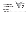
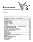
SPECIFICATIONS - CPU
MODULES
In This Chapter:
CHAPTER
3
CPU Specifications . . . . . . . . . . . . . . . . . . . . . . . . . . . . . . . . . . . . . . . . . . . . . . . . . 3–2
CPU General Specifications . . . . . . . . . . . . . . . . . . . . . . . . . . . . . . . . . . . . . . . . . . .3–2
Communications Ports Specifications . . . . . . . . . . . . . . . . . . . . . . . . . . . . . . . . . . .3–4
Port 1 Specifications (USB) . . . . . . . . . . . . . . . . . . . . . . . . . . . . . . . . . . . . . . . . . . . .3–4
Port 2 Specifications (Serial) . . . . . . . . . . . . . . . . . . . . . . . . . . . . . . . . . . . . . . . . . . .3–4
Port 3 Specifications (Ethernet) . . . . . . . . . . . . . . . . . . . . . . . . . . . . . . . . . . . . . . . .3–5
Ethernet Expansion I/O . . . . . . . . . . . . . . . . . . . . . . . . . . . . . . . . . . . . . . . . . . . . . .3–6
Status Indicators . . . . . . . . . . . . . . . . . . . . . . . . . . . . . . . . . . . . . . . . . . . . . . . . . . . .3–8
Mode Switch Functions . . . . . . . . . . . . . . . . . . . . . . . . . . . . . . . . . . . . . . . . . . . . . .3–8
Dip Switch Specifications . . . . . . . . . . . . . . . . . . . . . . . . . . . . . . . . . . . . . . . . . . . . .3–9
Battery Replacement . . . . . . . . . . . . . . . . . . . . . . . . . . . . . . . . . . . . . . . . . . . . . . . .3–12
Chapter 3: Specifications - CPU Modules
CPU Specifications
1
2
3
4
5
6
7
8
9
10
11
12
13
14
A
B
C
D
CPU General Specifications
CPU General Specifications
Feature
PWR
USB
TX
RUN
ROM
ERR
RX
H2-DM1
H2
2-DM1
2
DM1
TERM
RUN
N
STO
STOP
OP
USB
PGM
PORT
RS-232
R
S-232
SERIAL
S
ERIAL
Total Memory (bytes)
Ladder Memory (instruction words)
V-Memory (words)
Non-volatile V Memory (words)
D-memory (DWORDs)
Non-volatile D Memory (DWORDs)
R-memory (REAL DWORDs)
Non-volatile R Memory (REAL DWORDs)
Boolean execution/K
Stage Programming
Total I/O points available
X, Y, each configurable up to 65536 (2048 default); WX, WY (analog
in/out) each configurable up to 65536 (256 default)
Built-In communications ports
H2-DM1E
H2
2-DM1E
2
DM1E
E
TERM
ER
ER
RUN
USB
PGM
PORT
RS-232
SERIAL
1
0
/
1
0
0
3–2
E
T
H
E
R
N
E
T
STOP
50 uSec
Program Memory
Handheld Programmer
Programming Software for Windows
ETH
USB
TX
RX
262,144 bytes
65,536 instruction words
Configurable up to 65536 (4096 default)
Configurable up to 65536 (4096 default)
Configurable up to 65536 (4096 default)
Configurable up to 65536 (4096 default)
Configurable up to 65536 (4096 default)
Configurable up to 65536 (4096 default)
Yes
128 per Program code-block; number of code-blocks configurable to
memory limit
No
FREE Do-more Designer
USB, RS-232, Ethernet (10/100
USB, RS-232
Base-T)
Flash ROM
Number of Stages
PWR
RUN
ROM
ERR
H2-DM1E
H2-DM1
Local I/O points available
Ethernet Remote I/O Discrete points
Ethernet Remote I/O Analog I/O
Channels
Max Number of Ethernet slaves per
Channel
I/O points per Remote Channel
Discrete I/O Module Point Density
Slots per Base
Number of instructions available
Control relays
Special relays (system defined)
Special registers (system defined)
Timers
Counters
System Date/Time structures
256
131,072
32,768
16
32,768
4/8/12/16/32
3/4/6/9
>160
>170
Configurable up to 65536 (2048 default)
1024
512
Configurable up to 65536 (256 default)
Configurable up to 65536 (256 default)
8
Do-more H2 Series PLC Hardware User Manual, 1st Edition, Rev. C - H2-DM-M
Chapter 3: Specifications - CPU Modules
Feature
CPU General Specifications (continued)
H2-DM1
User Date/Time structures
ASCII String/Byte buffer structures
Modbus Client memory
DL Classic Client memory
Immediate I/O
Interrupt input (hardware / timed)
Subroutines
Drum Timers
Table Instructions
Loops
H2-DM1E
Configurable up to 65536 (32 default)
Configurable up to memory limit (192 default)
Yes, configurable up to memory limit, default 1024 input bits, 1024 coil bits, 2048
input registers, 2048 holding registers
Math
Up to memory limit, default 512 X, 512 Y, 512 C, 2048 V
No
No
Program and Task code-blocks, up to memory limit
Yes, up to memory limit
Yes
FOR/NEXT, WHILE/WEND, REPEAT/UNTIL loops
>60 operators and functions: Integer, Floating Point, Trigonometric, Statistical, Logical,
Bitwise, Timing
ASCII
Yes, IN/OUT, Serial, Ethernet TCP and UDP; 11 output script commands
PID Loop Control, Built In
Time of Day Clock/Calendar
Run Time Edits
Supports True Force
Internal Diagnostics
Password security
System error log
User error log
Battery backup
Yes, configurable to memory limit (over 2,000)
Yes
Yes
Yes
Yes
Multi-user, credentialed, session-based security
Yes
Yes
Yes (Battery included)
Do-more H2 Series PLC Hardware User Manual, 1st Edition, Rev. C - H2-DM-M
1
2
3
4
5
6
7
8
9
10
11
12
13
14
A
B
C
D
3–3
Chapter 3: Specifications - CPU Modules
Communications Ports Specifications
1
2
3
4
5
6
7
8
9
10
11
12
13
14
A
B
C
D
Port 1 Specifications (USB)
USB Port: This port has a USB Type B female connector and requires a USB Type A-B cable.
• Do-more programming protocol only
USB Type B Slave Input Specifications
Description
Standard USB 2.0 Slave input for programming and online
monitoring only, with built-in surge protection. Not
compatible with older full speed USB devices.
Cables
USB Type A to USB Type B:
(ADC part #)
USB-CBL-AB3 (3 ft.)
USB-CBL-AB6 (6 ft.)
USB-CBL-AB10 (10 ft.)
USB-CBL-AB15 (15 ft.)
USB Port 1
1
2
3
4
5V
Bus Voltage Sense
D-
Data -
D+
Data +
0V
Ground
Port 2 Specifications (Serial)
RS-232 Port: Serial RS-232 multipurpose communications port with RJ12 connector.
RJ-12 style connector used for:
• Do-more programming protocol
• Modbus RTU Master connections
• Modbus RTU Slave connections
• ASCII Incoming and Outgoing communications
• Custom Protocol Incoming and Outgoing communications
RS-232 Specifications
Description
Non-isolated, full duplex RS-232 DTE port used for programming, online monitoring or
can connect the CPU as an ASCII or Modbus RTU master or slave to a peripheral
device. Includes ESD and built-in surge protection.
Baud Rates
+5V Cable Power Source
Maximum Output Load (TXD/RTS)
1200, 2400, 4800, 9600, 19200, 38400, 57600, and 115200.
220mA maximum at 5V, +/- 5%. Reverse polarity and overload protected.
3K ⍀, 1,000pf
Minimum Output Voltage Swing
Output Short Circuit Protection
Cable Options
+/-5V
+/-15mA
D2-DSCBL
USB-RS232 with D2-DSCBL
FA-CABKIT
FA-ISOCON for converting RS-232 to isolated RS-422/485
EA-MG-PGM
3–4
Do-more H2 Series PLC Hardware User Manual, 1st Edition, Rev. C - H2-DM-M
Chapter 3: Specifications - CPU Modules
RS-232 Port 2
1
2
3
4
5
6
0V
Power (-) connection (GND)
5V
Power (+) connection (220mA max)
RXD
Receive Data (RS-232)
TXD
Transmit Data (RS-232)
RTS
Request to Send (RS-232)
CTS
Clear to Send (RS-232)
1
2
3
4
5
6
7
8
Port 3 Specifications (Ethernet)
Ethernet Port: Programming and Modbus TCP Client/Server port with 10/100 Base-T
Ethernet RJ45 connector.
RJ-45 style connector used for:
• Do-more programming protocol
• Modbus TCP Client connections (Modbus requests sent from the CPU)
• Modbus TCP Server connections (Modbus requests received by the CPU)
• Ethernet Expansion I/O Master
Ethernet Specifications
Description
Standard transformer isolated Ethernet port with built-in surge
protection for programming, online monitoring, Modbus/TCP
client/server connections (fixed IP or DHCP) and Ethernet
Expansion I/O capabilities.
Transfer Rate
10/100 Mbps
Cables
Use a Patch (straight through) cable when a switch or hub is
used.
Use a Crossover cable when a switch or hub is not used.
NOTE: The above diagram illustrates the standard wire positions in the RJ45 connector. It is recommended
that all 10/100 Base-T cables be Category 5, UTP cables.
Do-more H2 Series PLC Hardware User Manual, 1st Edition, Rev. C - H2-DM-M
9
10
11
12
13
14
A
B
C
D
3–5
Chapter 3: Specifications - CPU Modules
1
2
3
4
5
6
7
8
9
10
11
12
13
14
A
B
C
D
Ethernet Expansion I/O
3–6
With Do-more Designer Software version V1.1 and newer, the H2-DM1E CPU’s built-in
Ethernet port can be configured as an Ethernet Expansion I/O master. Much like the ERM
module discussed in Chapter 7, the Ethernet Expansion I/O feature allows expansion beyond
the local chassis to slave I/O using the onboard high-speed Ethernet link.
The onboard Ethernet port can support up to 16 slave devices. The slave I/O modules
supported are:
• H2-EBC100
• T1H-EBC100 (Terminator I/O)
• GS-EDRV100 (GS Drives)
The Ethernet Expansion I/O network uses Category 5 UTP cables for cable runs up to 100
meters (328 ft.) with extended distances achieved through Ethernet switches.
Ethernet Expansion Example
Stride
Ethernet
Switch
Do-more H2-DM1E CPU
H2-DM1E
DirectLOGIC
DL205 I/O with
H2-EBC100
Module
C-more Operator
Interface
GS-EDRV100
Terminator I/O
with T1H-EBC100
Module
GS
Drive
WARNING: It is highly recommended that a dedicated network be used with the Ethernet Expansion I/O
feature. Ethernet Expansion I/O networks and ECOM/office networks should be isolated from one
another to prevent network delays. While Ethernet networks can handle a large number of data
transactions, and normally handle them very quickly, heavy Ethernet traffic can adversely affect the
reliability of the slave I/O and the speed of the I/O network.
Do-more H2 Series PLC Hardware User Manual, 1st Edition, Rev. C - H2-DM-M
Chapter 3: Specifications - CPU Modules
Ethernet Expansion I/O functionality is enabled through the System
Configuration dialog of Do-more Designer.
Under the PLC drop down menu, select System Configuration. Then, from
the System Configuration window select the CPU Configuration option
under the Configuration Entries column. Finally, left-click the Enable
Ethernet I/O Master checkbox in the Ethernet I/O Master section of the
H2-DM1E CPU Configuration window as seen below.
For more information on the setup, use and options available with Ethernet Expansion I/O,
refer to the Ethernet I/O Master section of Do-more Designer Help File topic DMD0247.
Do-more H2 Series PLC Hardware User Manual, 1st Edition, Rev. C - H2-DM-M
1
2
3
4
5
6
7
8
9
10
11
12
13
14
A
B
C
D
3–7
Chapter 3: Specifications - CPU Modules
Status Indicators
Do-more controllers in the DL205 series have two-color LEDs that are used to visually
1
provide operational status to the user.
LED Indicators
2
Indicator Status
Description
3
PWR
H2-DM1
H2
2-DM1
DM1
H2-DM1E
H2
2-DM1E
DM1E
E
4
In addition to the individual definition RUN
5
of each LED, there are times when the
controllers will use combinations of the
ROM
LED ON/OFF state and colors to
6
convey status information. The
following combinations use some or all ERR
7
of the LEDs:
• ERR LED is blinking RED for (15
ETH
8
seconds) - Do-more Designer can
blink the ERR led for 15 seconds to
USB
verify that a communication link is
9
targeting the correct controller.
TX
• All eight (8) of the LEDs are ON and
RX
the color of each LED is GREEN 10
indicates the operating system has started running.
•
All eight (8) of the LEDs are cycling through RED and GREEN, in a circular 'chase' pattern 11
indicates the operating system is initializing.
• The left-most four (4) LEDs are cycling through RED and GREEN, in a 'bouncing ball' pattern 12
indicates the controller is running only the boot loader and is NOT going to load and run the
operating system. The most likely cause is having DIP switch #1 in the ON position.
• All eight (8) of the LEDs are ON and the color of each LED is RED - indicates the hardware
13
watchdog timer has expired because the controller's operating system has stopped running.
14 Mode Switch Functions
The mode switch on the Do-more CPU allows the user to externally select the different
A
modes of operation. There are three modes available: RUN, TERM and STOP.
B
Mode Switch Functions
Mode Switch Position
CPU Action
RUN (Run Program)
C
TERM (Terminal)
D
PWR
RUN
ROM
ERR
PWR
ETH
USB
TX
RUN
ROM
ERR
RX
USB
TX
RX
Base Power ON
Yellow
Low Battery
OFF
CPU is in STOP Mode
Green
CPU is in RUN Mode
Yellow
Forces are Active
OFF
Non-volatile Memory is up to date
Yellow
CPU is updating Non-volatile Memory
OFF
CPU is functioning normally
Red
CPU Fatal Hardware Error or Software
Watchdog Error
Green
Ethernet Link Good
Yellow
Ethernet Activity
Green
USB Receive Activity
Yellow
USB Transmit Activity
Green
RS-232 Transmit Activity
Green
RS-232 Receive Activity
RUN, PROGRAM and the DEBUG modes are available. In
this mode, the mode of operation can be changed through
the Do-more Designer Software.
STOP
STOP (Stop Program)
3–8
Base Power OFF
CPU is forced into RUN Mode if no errors are encountered.
TERM
ER
ER
RUN
OFF
Green
CPU is forced into STOP Mode.
Do-more H2 Series PLC Hardware User Manual, 1st Edition, Rev. C - H2-DM-M
Chapter 3: Specifications - CPU Modules
As mentioned in the previous table, the CPU mode can also be changed through the
programming software if the mode switch is placed in the TERM position. In this position,
the CPU can be changed remotely between the Run and Program modes. For more
information on changing CPU modes through the software, see the “Step 9: Write Project to
the Do-more PLC” section of Chapter1 “Getting Started”.
When power is applied to the system, the controller will go through it's power-up sequence
then either stay in Program mode if the mode switch is in the STOP position, or attempt to
go to Run mode if the mode switch is in the RUN position.
If the mode switch is in the TERM position, the controller will return to the last operational
mode before power was lost. For example, if the controller was in Run mode when power was
lost, when power is restored and the mode switch is in the TERM position, the controller will
attempt to return to Run mode.
DIP Switch Specifications
Do-more controller's circuit board has a block of DIP switches that are used to perform
various debug and reset operations. The DIP switch settings are only read when the system is
first powered up. Changing the settings of the DIP switches requires that the base containing
the controller be powered down and the controller removed from the base. The DIP switches
can then be changed as required. The controller can then be reinstalled in the base and the
system powered back up. The DIP switch block is located on front of the controller's PWB,
and is only accessible when the controller is NOT installed in the base.
0
1
ON
Switch
Number
76543210
The default position for all of the
DIP switches is OFF. The
following table describes the
position and function associated
with each DIP switch.
DIP Switch Settings
Switch
Function
Position
ON
Load the oldest copy of the operating system.
ON
Do not load an Operating System, stay in the Booter.
2
ON
Disable the hardware watchdog timer - the hardware
watchdog is always enabled, but this switch allows the
user to override the ability of the Force Watchdog Error
(WATCHDOG) and Debug Mode to generate a
Watchdog condition.
3
4
5
6
ON
Disable ability to update the firmware and/or gate array.
ON
Reserved
ON
Reserved
ON
Reserved
7
ON
Reset the TCP/IP Network Settings to factory default
values - Must be used with DIP #1
Do-more controllers make use of
combinations of DIP switch settings
and the Mode switch on the front of the
controller to perform two reset
functions. These reset functions can
only be performed when the controller
is in the boot loader.
Do-more H2 Series PLC Hardware User Manual, 1st Edition, Rev. C - H2-DM-M
1
2
3
4
5
6
7
8
9
10
11
12
13
14
A
B
C
D
3–9
Chapter 3: Specifications - CPU Modules
1
2
3
4
5
6
7
8
9
10
11
12
13
14
A
B
C
D
The following sequence describes the steps necessary to perform one of the reset operations.
This combination of DIP switch settings and mode switch manipulation is purposely
complex to prevent these reset operations from being accidentally executed.
Clear only the Network Settings
This reset function will clear ONLY the Network settings, which consists of the Module ID,
Module Name, Module Description, IP Address, Subnet Mask and Gateway Address.
• Begin by powering down the controller.
• Remove the controller from the base and record the location of the DIP switches (so they can be set
back to their original position after the manual reset is finished).
• Next set ONLY DIP #1 and #7 ON to perform the Clear Only the Network Settings operation, make
sure all other DIP switches are OFF.
• Reinstall the controller in the base.
• Set the controller mode switch to TERM (the center location) and power up the controller.
• At this point the LEFT bank of 4 LEDs should be blinking the 'stay in the boot loader sequence', that
is, they should be blinking in sequence, from top to bottom then back to the top, alternating between
red and green.
• Move the controller mode switch to RUN (to the left).
• Move the controller mode switch to TERM (to the center).
• Move the controller mode switch to RUN (to the left).
• Move the controller mode switch to TERM (to the center).
• Move the controller mode switch to STOP (to the right).
• Move the controller mode switch to TERM (to the center) - the LEFT bank of 4 LEDs should now
be ON.
NOTE: If you want to terminate the reset at this point you can do so by moving switch to RUN instead of
STOP or powering down the controller.
• Move the controller mode switch to STOP (to the right) - the RIGHT bank of 4 LEDs should now
be ON.
NOTE: If you want to terminate the manual reset at this point you can only do so by powering down the
controller.
• Move the controller mode switch to TERM (to the center) - the LEFT bank LEDs begin flashing the
power up sequence, and the ROM led should briefly be ON indicating that the data in the ROM is
being rewritten. The LEDs will then begin flashing the 'staying in boot loader' sequence indicating
the reset is complete.
• Power down the controller.
• Remove the controller from the base and return the DIP switches to their original positions.
• Set the controller mode switch to TERM (in the center location).
3–10
Do-more H2 Series PLC Hardware User Manual, 1st Edition, Rev. C - H2-DM-M
Chapter 3: Specifications - CPU Modules
Clear All
This reset function will clear everything from the controller, this includes the Network
Settings as described previously, and the System Configuration, Memory Configuration, all
control logic, all Documentation, and all of the User Accounts and Passwords.
• Begin by powering down the controller.
• Remove the controller from the base and record the location of the DIP switches (so they can be set
back to their original position after the manual reset is finished).
• Next set all eight of the DIP switches ON to perform the Clear All operation.
• Reinstall the controller in the base.
• Set the controller mode switch to TERM (the center location) and power up the controller.
• At this point the LEFT bank of 4 LEDs should be blinking the 'stay in the boot loader sequence',
that is, they should be blinking in sequence, from top to bottom then back to the top, alternating
between red and green.
• Move the controller mode switch to RUN (to the left).
• Move the controller mode switch to TERM (to the center).
• Move the controller mode switch to RUN (to the left).
• Move the controller mode switch to TERM (to the center).
• Move the controller mode switch to STOP (to the right).
• Move the controller mode switch to TERM (to the center) - the LEFT bank of 4 LEDs should now
be ON.
NOTE: If you want to terminate the reset at this point you can do so by moving switch to RUN instead of
STOP or powering down the controller.
• Move the controller mode switch to STOP (to the right) - the RIGHT bank of 4 LEDs should now
be ON.
NOTE: If you want to terminate the manual reset at this point you can only do so by powering down the
controller.
• Move the controller mode switch to TERM (to the center) - the LEFT bank LEDs begin flashing the
power up sequence, and the ROM led should briefly be ON indicating that the data in the ROM is
being rewritten. The LEDs will then begin flashing the 'staying in boot loader' sequence indicating
the reset is complete.
• Power down the controller.
• Remove the controller from the base and return the DIP switches to their original positions.
• Set the controller mode switch to TERM (in the center location).
Do-more H2 Series PLC Hardware User Manual, 1st Edition, Rev. C - H2-DM-M
1
2
3
4
5
6
7
8
9
10
11
12
13
14
A
B
C
D
3–11
Chapter 3: Specifications - CPU Modules
1
2
3
4
5
6
7
8
9
10
11
12
13
14
A
B
C
D
Battery Replacement
3–12
All Do-more controllers have an onboard battery that maintains the contents of the retentive
memory any time the power to the controller is lost. The battery has an expected lifespan of
three years; after which the battery will need to be replaced. The battery is a standard
CR2032, coin cell battery.
When the controller detects that the battery voltage is too low, and needs to be replaced, the
PWR LED will be YELLOW instead of it's normal GREEN color. When Do-more Designer
is online with the controller, the system-defined location $BatteryLow will be ON as well.
NOTE: Make sure to have a current copy of the Do-more Designer project saved to Disk before performing
this operation.
• Power down the system containing the controller.
• Remove the controller from the base.
• Remove the battery from it's holder that is located on the back of the controller's PWB,
in the lower right corner. The battery is removed by pushing on the back of the battery
to begin sliding it out of the holder, then pulling it the rest of the way out by the front
edge of the battery. Make note of how the battery is aligned in the holder.
H2-DM1 and H2-DM1E
Battery Replacement
Part # D0-MC-BAT.
NOTE: The controller has an onboard capacitor that will maintain the retentive memory contents while the
battery is being replaced. This capacitor has a two-hour runtime, which should be more than enough to
replace the battery.
•
•
•
•
Insert the new battery into the holder, making sure the alignment is correct.
Reinstall the controller in the base.
Power up the system containing the controller.
Verify that the PWR LED is now GREEN instead of YELLOW and the system-defined
location $BatteryLow will be OFF.
Do-more H2 Series PLC Hardware User Manual, 1st Edition, Rev. C - H2-DM-M