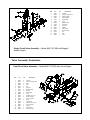
1
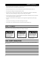
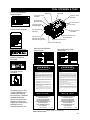
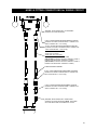
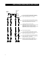
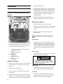
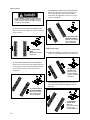
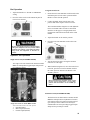
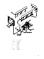
MHP1
Mobile Hydraulic Power Unit
Safety, Operation and Routine Maintenance
User's Manual
SERIOUS INJURY OR DEATH COULD
RESULT FROM THE IMPROPER REPAIR OR SERVICE OF THIS TOOL.
REPAIRS AND / OR SERVICE TO THIS
TOOL MUST ONLY BE DONE BY AN
AUTHORIZED AND CERTIFIED
DEALER.
Stanley Hydraulic Tools
Copyright © 2000 The Stanley Works
All Rights Reserved
OPS/MAINT USA & CE VERSION
Printed in U.S.A.
35599 01/2003 Ver 5
3810 SE Naef Road
Milwaukie, OR 97267-5698 USA
Phone: (503) 659-5660
Fax: (503) 652-1780
CONTENTS
Accessories ........................................................................................... 17
Disengaging Gear Boxes ........................................................................ 16
Hydraulic Hose Requirements .................................................................. 5
Hydraulic Hose & Fitting Connections ................................................. 6 - 7
Loading & Unloading ........................................................................ 13 - 14
Operation .......................................................................................... 8 - 13
Parts Lists ....................................................................................... 18 - 23
Routine Maintenance ....................................................................... 14 - 15
Safety Precautions .............................................................................. 2 - 3
Specifications ......................................................................................... 17
Tool Stickers and Tags ............................................................................. 4
Transporting ........................................................................................... 14
Troubleshooting ...................................................................................... 16
Warranty ................................................................................................ 25
Wiring Diagram ....................................................................................... 24
SERVICING THE MHP1: This manual contains safety, operation, and routine maintenance instructions. Stanley Hydraulic Tools recommends that servicing of this equipment, other than routine
maintenance, must be performed by an authorized and certified dealer. Please read the following warning.
SERIOUS INJURY OR DEA
TH COULD RESUL
T FROM
DEATH
RESULT
THE IMPROPER REP
AIR OR SERVICE OF THIS TOOL
REPAIR
TOOL..
REP
AIRS AND / OR SERVICE TO THIS TOOL MUST
REPAIRS
ONL
Y BE DONE B
Y AN A
UTHORIZED AND CERTIFIED
ONLY
BY
AUTHORIZED
DEALER.
1
SAFETY
Tool operators and maintenance personnel must always comply with the safety
precautions given in this manual and on the stickers and tags attached to the
machine.
These safety precautions are given for your safety. Review them carefully before
operating the machine and before performing general maintenance or routine
service.
Supervising personnel should develop additional precautions relating to the
specific work area and local safety regulations. If so, place the added precautions in
the space provided on page 3.
GENERAL SAFETY PRECAUTIONS
If you have not read this manual or the engine manual, you are not ready to operate the
MHP1. Read and understand this manual and any stickers and tags attached to the
machine before operation. Failure to do so can result in equipment damage, personal
injury, or death.
•
Operate the machine in a work area without bystanders. The operator must be familiar with all prohibited work
areas such as excessive slopes and dangerous terrain conditions.
•
DO NOT operate the machine ACROSS excessive slopes where "tip over" is a hazard.
•
DO NOT operate the machine in confined areas where there may be a risk of crushing the operator between the
machine and another object.
•
DO NOT operate the machine in enclosed spaces. Inhalation of engine exhaust can be fatal.
•
DO NOT wear loose clothing that can get entangled in the working parts of the machine or hydraulic tools.
•
DO NOT add fuel to the machine while it is running or still hot.
•
DO NOT operate the machine if a fuel odor is present.
•
DO NOT operate the machine within 3.3 ft./1 m of buildings, obstructions, or flammable objects.
•
Allow the engine to cool before storing the machine in an enclosure.
•
DO NOT ride on, or allow anyone else to ride on, the machine at any time.
•
Establish a training program for all operators to ensure safe operation.
•
DO NOT operate the machine unless thoroughly trained or under the supervision of an instructor.
•
Always wear safety equipment such as goggles, ear, head protection, and safety shoes at all times when operating the machine.
•
DO NOT inspect or clean the machine while the engine is running. Accidental engagement of the machine can
cause serious injury or death.
•
The hydraulic circuit control valve must be in the "OFF"position when coupling or uncoupling hydraulic tools.
2
SAFETY Continued . . .
Wipe all couplers clean before connecting. Use only lint-free cloths. Failure to do so may result in damage to the
quick couplers and cause overheating of the hydraulic system.
•
Before operating hydraulic tools, read and understand the operation manual furnished with the tool.
•
DO NOT operate a damaged, or improperly adjusted, machine.
•
DO NOT weld or cut with an acetylene torch any surface or component of the equipment. Consult with the
Stanley factory before performing any welding or acetylene cutting of the equipment.
•
Prevent possible personal injury or equipment damage by having all repair, maintenance and service performed
only by authorized and properly trained personnel.
•
DO NOT exceed the rated limits of the equipment or use the equipment for applications beyond its design
capacity.
•
Always keep critical markings, such as lables and warning stickers legible.
•
Always replace parts with replacement parts recommended by Stanley Hydraulic Tools.
SAFETY SYMBOLS
Safety symbols are used to emphasize all operator, maintenance and repair actions which, if not strictly followed,
could result in a life-threatening situation, bodily injury or damage to equipment.
This safety symbol may
appear on the machine. It is
used to alert the operator of
an action that could place
him/her or others in a life
threatening situation.
This safety symbol appears in
these instructions to identify
an action that could cause
bodily injury to the operator or
other personnel.
This safety symbol appears in
these instructions to identify
an action or condition that
could result in damage to the
tool or other equipment.
Always observe safety symbols. They are included for your safety and for the protection of the tool.
LOCAL SAFETY REGULATIONS
Enter any local safety regulations here. Keep these instructions in an area accessible to the operator and maintenance personnel.
3
TOOL STICKERS & TAGS
Stanley Decal
P/N-05154
Dual Circuit Valve Block
Decal P/N-28045
TracHorse Decal
P/N-59046
Lift Location Decal
P/N-59045
TracHorse Decal
P/N-59046
Hydraulic Fluid
Decal P/N-35686
Lift Location Decal
P/N-59045
Limit Engine Speed
Decal P/N-59044
Caution Decal P/N-28089
Gas Throttle Decal
P/N-59043
TracHorse Decal
P/N-59046
Dual Circuit Valve block
Decal P/N-28045
Start-Up Decal
P/N-59041 (Dual Circuit)
P/N-59042 (Single Circuit)
Choke Decal P/N-07764
Caution Decal P/N-28089
Choke Decal P/N-07764
Start-Up Decal P/N 59042
(Single Circuit)
Start-Up Decal P/N 59041
(Dual Circuit)
Hydraulic Fluid Decal
P/N-35686
D A N G E R
Lift Location Decal
P/N-59045
D A N G E R
1. FAILURE TO USE HYDRAULIC HOSE LABELED AND CERTIFIED
AS NON-CONDUCTIVE WHEN USING HYDRAULIC TOOLS ON
OR NEAR ELECTRICAL LINES MAY RESULT IN DEATH OR SERIOUS INJURY.
BEFORE USING HOSE LABELED AND CERTIFIED AS NON-CONDUCTIVE ON OR NEAR ELECTRIC LINES BE SURE THE HOSE IS
MAINTAINED AS NON-CONDUCTIVE. THE HOSE SHOULD BE
REGULARLY TESTED FOR ELECTRIC CURRENT LEAKAGE IN
ACCORDANCE WITH YOUR SAFETY DEPARTMENT INSTRUCTIONS.
2. A HYDRAULIC LEAK OR BURST MAY CAUSE OIL INJECTION
INTO THE BODY OR CAUSE OTHER SEVERE PERSONAL INJURY.
A
DO NOT EXCEED SPECIFIED FLOW AND PRESSURE FOR
THIS TOOL. EXCESS FLOW OR PRESSURE MAY CAUSE A
LEAK OR BURST.
B
DO NOT EXCEED RATED WORKING PRESSURE OF HYDRAU
LIC HOSE USED WITH THIS TOOL. EXCESS PRESSURE MAY
CAUSE A LEAK OR BURST.
C CHECK TOOL HOSE COUPLERS AND CONNECTORS DAILY
FOR LEAKS. DO NOT FEEL FOR LEAKS WITH YOUR HANDS.
CONTACT WITH A LEAK MAY RESULT IN SEVERE PERSONAL
INJURY.
The safety tag (p/n 15875)
at right is attached to the
machine when shipped
from the factory. Read and
understand the safety
instructions listed on this
tag before removal. We
suggest you retain this tag
and attach it to the
machine when not in use.
D DO NOT LIFT OR CARRY TOOL BY THE HOSES. DO NOT
ABUSE HOSE. DO NOT USE KINKED, TORN OR DAMAGED
HOSE.
3. MAKE SURE HYDRAULIC HOSES ARE PROPERLY CONNECTED
TO THE TOOL BEFORE PRESSURING SYSTEM. SYSTEM PRESSURE HOSE MUST ALWAYS BE CONNECTED TO TOOL "IN" PORT.
SYSTEM RETURN HOSE MUST ALWAYS BE CONNECTED TO TOOL
"OUT" PORT. REVERSING CONNECTIONS MAY CAUSE REVERSE
TOOL OPERATION WHICH CAN RESULT IN SEVERE PERSONAL
INJURY.
4. DO NOT CONNECT OPEN-CENTER TOOLS TO CLOSED-CENTER
HYDRAULIC SYSTEMS. THIS MAY RESULT IN LOSS OF OTHER
HYDRAULIC FUNCTIONS POWERED BY THE SAME SYSTEM AND/
OR SEVERE PERSONAL INJURY.
5. BYSTANDERS MAY BE INJURED IN YOUR WORK AREA. KEEP BYSTANDERS CLEAR OF YOUR WORK AREA.
6. WEAR HEARING, EYE, FOOT, HAND AND HEAD PROTECTION.
7. TO AVOID PERSONAL INJURY OR EQUIPMENT DAMAGE, ALL TOOL
REPAIR MAINTENANCE AND SERVICE MUST ONLY BE PERFORMED BY AUTHORIZED AND PROPERLY TRAINED PERSONNEL.
I M P O R TA N T
I M P O R TA N T
READ OPERATION MANUAL AND
SAFETY INSTRUCTIONS FOR THIS
TOOL BEFORE USING IT.
READ OPERATION MANUAL AND
SAFETY INSTRUCTIONS FOR THIS
TOOL BEFORE USING IT.
USE ONLY PARTS AND REPAIR
PROCEDURES APPROVED BY
STANLEY AND DESCRIBED IN THE
OPERATION MANUAL.
USE ONLY PARTS AND REPAIR
PROCEDURES APPROVED BY
STANLEY AND DESCRIBED IN THE
OPERATION MANUAL.
TAG TO BE REMOVED ONLY BY
TOOL OPERATOR.
TAG TO BE REMOVED ONLY BY
TOOL OPERATOR.
SEE OTHER SIDE
15875
SEE OTHER SIDE
15875
SAFETY TAG P/N 15875 (shown smaller then actual size)
4
TOOL CIRCUIT HYDRAULIC HOSE REQUIREMENTS
HOSE TYPES
Hydraulic hose types authorized for use with Stanley Hydraulic Tools are as follows:
➊ Certified non-conductive
➋ Wire-braided (conductive)
➌ Fabric-braided (not certified or labeled non-conductive)
Hose ➊ listed above is the only hose authorized for use near electrical conductors.
Hoses ➋ and ➌ listed above are conductive and must never be used near electrical conductors.
HOSE SAFETY TAGS
To help ensure your safety, the following DANGER tags are attached to all hose purchased from Stanley Hydraulic
Tools. DO NOT REMOVE THESE TAGS.
If the information on a tag is illegible because of wear or damage, replace the tag immediately. A new tag may be
obtained at no charge from your Stanley Distributor.
D A N G E R
D A N G E R
1 FAILURE TO USE HYDRAULIC HOSE LABELED AND CERTIFIED AS NON-CONDUCTIVE WHEN
USING HYDRAULIC TOOLS ON OR NEAR ELECTRIC LINES MAYRESULT IN DEATH OR SERIOUS
INJURY.
FOR PROPER AND SAFE OPERATION MAKE SURE THAT YOU HAVE BEEN PROPERLY TRAINED IN
CORRECT PROCEDURES REQUIRED FOR WORK ON OR AROUND ELECTRIC LINES.
3. DO NOT EXCEED HOSE WORKING PRESSURE OR ABUSE HOSE. IMPROPER USE OR HANDLING
OF HOSE COULD RESULT IN BURST OR OTHER HOSE FAILURE. KEEP HOSE AS FAR AWAY AS
POSSIBLE FROM BODY AND DO NOT PERMIT DIRECT CONTACT DURING USE. CONTACT AT THE
BURST CAN CAUSE BODILY INJECTION AND SEVERE PERSONAL INJURY.
2. BEFORE USING HYDRAULIC HOSE LABELED AND CERTIFIED AS NON-CONDUCTIVE ON OR
NEAR ELECTRIC LINES. WIPE THE ENTIRE LENGTH OF THE HOSE AND FITTING WITH A CLEAN
DRY ABSORBENT CLOTH TO REMOVE DIRT AND MOSISTURE AND TEST HOSE FOR MAXIMUM
ALLOWABLE CURRENT LEAKAGE IN ACCORDANCE WITH SAFETY DEPARTMENT
INSTRUCTIONS.
4. HANDLE AND ROUTE HOSE CAREFULLY TO AVOID KINKING, ABRASION, CUTTING, OR CONTACT
WITH HIGH TEMPERATURE SURFACES. DO NOT USE IF KINKED. DO NOT USE HOSE TO PULL OR
LIFT TOOLS, POWER UNITS, ETC.
5. CHECK ENTIRE HOSE FOR CUTS CRACKS LEAKS ABRASIONS, BULGES, OR DAMAGE TO
COUPLINGS IF ANY OF THESE CONDITIONS EXIST, REPLACE THE HOSE IMMEDIATELY. NEVER
USE TAPE OR ANY DEVICE TO ATTEMPT TO MEND THE HOSE.
DO NOT REMOVE THIS
TA G
DO NOT REMOVE THIS
TA G
The tag shown below is attached to "certified non-conductive" hose.
6. AFTER EACH USE STORE IN A CLEAN DRY AREA.
SEE OTHER SIDE
3
SIDE 1
SEE OTHER SIDE
(shown smaller than actual size)
SIDE 2
The tag shown below is attached to "conductive" hose.
DO NOT REMOVE THIS
TA G
1 DO NOT USE THIS HYDRAULIC HOSE ON OR NEAR ELECTRIC LINES. THIS HOSE IS NOT
LABELED OR CERTIFIED AS NON-CONDUCTIVE. USING THIS HOSE ON OR NEAR ELECTRICAL
LINES MAY RESULT IN DEATH OR SERIOUS INJURY.
2. FOR PROPER AND SAFE OPERATION MAKE SURE THAT YOU HAVE BEEN PROPERLY TRAINED IN
CORRECT PROCEDURES REQUIRED FOR WORK ON OR AROUND ELECTRIC LINES.
5. CHECK ENTIRE HOSE FOR CUTS CRACKS LEAKS ABRASIONS, BULGES, OR DAMAGE TO
COUPLINGS IF ANY OF THESE CONDITIONS EXIST, REPLACE THE HOSE IMMEDIATELY. NEVER
USE TAPE OR ANY DEVICE TO ATTEMPT TO MEND THE HOSE.
6. AFTER EACH USE STORE IN A CLEAN DRY AREA.
3. DO NOT EXCEED HOSE WORKING PRESSURE OR ABUSE HOSE. IMPROPER USE OR HANDLING
OF HOSE COULD RESULT IN BURST OR OTHER HOSE FAILURE. KEEP HOSE AS FAR AWAY AS
POSSIBLE FROM BODY AND DO NOT PERMIT DIRECT CONTACT DURING USE. CONTACT AT
THE BURST CAN CAUSE BODILY INJECTION AND SEVERE PERSONAL INJURY.
4. HANDLE AND ROUTE HOSE CAREFULLY TO AVOID KINKING, CUTTING, OR CONTACT WITH
HIGH TEMPERATURE SURFACES. DO NOT USE IF KINKED. DO NOT USE HOSE TO PULL OR LIFT
TOOLS, POWER UNITS, ETC.
DO NOT REMOVE THIS
TA G
D A N G E R
D A N G E R
SEE OTHER SIDE
SEE OTHER SIDE
SIDE 1
(shown smaller than actual size)
SIDE 2
HOSE PRESSURE RATING
The rated working pressure of the hydraulic hose must be equal to or higher than the relief valve setting on the hydraulic
system.
5
HOSE & FITTING CONNECTIONS for SINGLE CIRCUIT
ADAPTER, 1/2 INCH MALE PIPE x -10 SAE O-RING
(STANLEY P/N 07882 ADAPTER)
H.T.M.A. 1/2 INCH FEMALE QUICK DISCONNECT COUPLER
(STANLEY P/N 24060 COUPLER BODY or STANLEY P/N
03974 COUPLER SET - nose & body)
H.T.M.A. 1/2 INCH MALE QUICK DISCONNECT COUPLER
(STANLEY P/N 24061 COUPLER NOSE or STANLEY P/N
03974 COUPLER SET - nose & body)
31972 Assy w/couplers.
31848 Hose Assy w/couplers
1/2 INCH I.D. HOSE, 25 FT TO 50 FT LONG.
(FOR 25 FEET, STANLEY P/N 04972 HYDRAULIC HOSE or
STANLEY P/N 05009 DUAL HYDRAULIC HOSES)
(FOR 50 FEET, STANLEY P/N 04978 HYDRAULIC HOSE or
STANLEY P/N 05008 DUAL HYDRAULIC HOSES)
1/2 INCH MALE PIPE HOSE END
H.T.M.A. 1/2 INCH FEMALE QUICK DISCONNECT COUPLER
(STANLEY P/N 24060 COUPLER BODY or STANLEY P/N
03974 COUPLER SET - nose & body)
H.T.M.A. 1/2 INCH MALE QUICK DISCONNECT COUPLER
(STANLEY P/N 24061 COUPLER NOSE or STANLEY P/N
03974 COUPLER SET - nose & body)
ADAPTER, 3/8 INCH MALE PIPE x -8 SAE O-RING
(STANLEY P/N 00936 ADAPTER) NOTE: ADAPTERS
OR HOSE WHIPS ARE INCLUDED WITH TOOLS.
6
HOSE & FITTING CONNECTIONS for DUAL CIRCUIT
TOOL COUPLERS
CONTROL
LEVER
VALVE BLOCK
H.T.M.A. 1/2 INCH MALE QUICK DISCONNECT COUPLER
(STANLEY P/N 24061 COUPLER NOSE or STANLEY P/N
03974 or 24070COUPLER SET - nose & body)
H.T.M.A. 1/2 INCH FEMALE QUICK DISCONNECT COUPLER
(STANLEY P/N 24060 COUPLER BODY or STANLEY P/N
03974 or 24070 COUPLER SET - nose & body)
1/2 INCH I.D. HOSE, 25 FT TO 50 FT LONG.
(FOR 25 FEET, STANLEY P/N 04978 HYDRAULIC HOSE or
STANLEY P/N 05008 DUAL HYDRAULIC HOSES)
(FOR 50 FEET, STANLEY P/N 04979 HYDRAULIC HOSE or
STANLEY P/N 05009 DUAL HYDRAULIC HOSES)
1/2 INCH MALE PIPE HOSE END
H.T.M.A. 1/2 INCH MALE QUICK DISCONNECT COUPLER
(STANLEY P/N 24061 COUPLER NOSE or STANLEY P/N
03974 or 24070 COUPLER SET - nose & body)
H.T.M.A. 1/2 INCH FEMALE QUICK DISCONNECT COUPLER
(STANLEY P/N 24060 COUPLER BODY or STANLEY P/N
03974 COUPLER SET - nose & body)
ADAPTER, 3/8 INCH MALE PIPE x -8 SAE O-RING
(STANLEY P/N 00936 ADAPTER) NOTE: ADAPTERS
OR HOSE WHIPS ARE INCLUDED WITH TOOLS.
7
OPERATING INSTRUCTIONS
PREOPERATION
PROCEDURES
Engine Fuel Level
Check the fuel level. If low, fill with unleaded
gasoline with a minimum of 85 octane rating.
Preparation For Initial Use
Warning Lights
The equipment, as shipped, has no special unpacking or
assembly requirements prior to usage. Inspection to
assure the equipment was not damaged in shipping,
does not contain packing debris, and checking fluid
levels as described below, is all that is required.
Engine Oil Level
Before each use, check the engine oil level. Make
sure the engine oil level is at the FULL MARK on
the dipstick. Do not overfill. Use detergent oil
classified "For Service SE, SF, SG" as specified in the
engine operating and maintenance manual.
Engine Oil
A warning light is located on the instrument panel
near the ignition key. The light comes on when the
ignition key is turned to the "ON" position. After the
engine is started, the light should turn off. If the light
stays on, the engine oil is low. Shut down the engine
immediately and check the engine oil level. Add oil
as required.
The engine oil dipstick is located on the right side of
the engine for both the Honda and B & S engines.
Engine Oil
Filler Cap
Low Engine Oil
Warning Light
Hydraulic Fluid
A warning light is located on the instrument panel
near the ignition key. The light DOES NOT COME
ON when the ignition key is turned to the "ON"
position unless the hydraulic fluid level is too low. If
the hydraulic fluid level is too low, the light will stay
on after the engine has been started. Shut down the
engine immediately and add hydraulic fluid as
required. When the hydraulic fluid level is correct,
the light should not be on.
Engine Oil
Dipstick
HONDA ENGINE
Engine Oil
Filler Cap
Engine Oil
Dipstick
BRIGGS & STRATTON
ENGINE
LowHydraulic
Fluid Warning
Light
Low hydraulic fluid indicates a leak in the hydraulic system. Inspect all hydraulic connections and hydraulic components for leaks.
DO NOT use the equipment until leaks are
repaired.
8
damage the starter motor.
OPERATION
Location of Instruments, Switches, and
Controls
1
5. After the engine starts, allow it to warm-up for a few
seconds before moving the choke. Move the choke
inward in small steps to allow the engine to accept
small changes in speed and load. Continue moving
the choke in until it is fully off and the engine is
running smoothly.
6. Adjust the throttle for the work to be done. See
"Adjusting Throttle For Various Types of Work".
2
Stopping The Engine
7
1. Move the throttle to the "SLOW" position.
3
8
4
6
5
9
2. Ensure the tool circuit control lever(s) are in the OFF
position and the tool circuit switch is in the "OFF"
position.
3. Turn the ignition key counter clockwise to the
"OFF" position.
Adjusting Throttle for Various Types of
Work
10
NOTE: Use caution when operating or ordering items 3 & 7 they
can come installed oppisite of what is illustrated above. The
Bed up/down switch is spring loaded and will return to the
center position when released. The tool ciucuit on/off switch
is either on or off (2 way) no center position.
1.
2.
3.
4.
5.
6.
7.
8.
9.
10.
Left & Right Track Controls for Forward, Reverse,
and Left, Right Steering
Throttle
Tool Circuit ON/OFF Switch
Hour Meter
Key Ignition
Warning Lights
Bed UP/DOWN Switch
Choke
Tool Circuit Controls
Fuel Shutoff
Starting The Engine
1. Ensure the tool circuit control lever(s) are in the OFF
position and the tool circuit switch is in the OFF
position.
2. Pull the choke out until it stops.
3. Move the throttle to a position between "SLOW"
and "FAST".
4. Turn the ignition key clockwise to begin cranking
the engine. Use short starting cycles (15 seconds per
minute) to prolong starter life. Extended cranking can
9
Forward Travel
The throttle can be positioned anywhere between
"SLOW" and "FAST" for traveling forward depending on the weight of the load being carried. Heavy
loads will require higher throttle settings in order for
the engine to provide enough power to move the
load.
Reverse Travel
Position the throttle to "SLOW" for reverse travel to
permit increased control and safety.
DO NOT attempt to travel in reverse with the
throttle positioned above "SLOW". This may
result in loss of control and result in injury
or death to the operator.
Bed Cylinder
The throttle may be positioned anywhere between
"SLOW" and "FAST" when operating the bed.
Tool Circuit
The throttle must be positioned to "FAST" when
using the tool circuit. Slower throttle settings will
stall the engine or provide reduced oil flow.
Slope Operation
DO NOT operate the machine on slopes exceeding 60
degrees in the travel direction or across slopes
exceeding 45 degrees..
Avoid turning on slopes. If you must turn, turn
slowly downhill, if possible.
DO NOT operate the machine near drop-offs,
ditches, or embankments. The machine could
suddenly turn over if a track goes over the edge or if
an edge collapses.
DO NOT try to stabilize the machine if it is tipping
over. Let go of the machine and get out of its way.
Traveling Forward or Reverse
TO TRAVEL FORWARD
Move Both Controls
Forward
TO TURN LEFT WHILE MOVING FORWARD:
Release the left track control while pushing forward
on the right track control. Resume pushing forward
on the left track control to move forward in a straight
line.
When first learning to operate the Track
Horse, position the throttle to the "SLOW"
position. More experienced operators
may use higher throttle settings.
TO TURN LEFT WHILE
MOVING FORWARD
Release left control
while holding right
control forward
TO TURN RIGHT WHILE MOVING FORWARD:
Release the right track control while pushing forward
on the left track control. Resume pushing forward on
the right track control to move forward in a straight
line.
Track Steering Controls
To travel forward, reverse, turn left, or turn right, do
the following:
Forward Travel
TO MOVE FORWARD IN A STRAIGHT LINE: Move
both the left and right track controls forward at the
same time.
TO TURN RIGHT WHILE
MOVING FORWARD
Release right control
while holding left
control forward
10
Reverse Travel
DO NOT attempt to travel in reverse with the
throttle positioned above "SLOW". This may
result in loss of control and result in injury
or death to the operator.
TO TURN RIGHT WHILE MOVING BACKWARD:
Release the right track control while pulling backward on the left track control. Resume pulling
backward on the right track control to move backward in a straight line.
TO MOVE BACKWARDS IN A STRAIGHT LINE:
Move both the left and right track controls backward
at the same time.
TO TURN RIGHT WHILE
MOVING BACKWARD
Release right control
while holding left
control backward
Turning From A Stop
TO TRAVEL BACKWARD
Move Both Controls
Backward
TO TURN LEFT WHILE MOVING BACKWARD:
Release the left track control while pulling backward
on the right track control. Resume pulling backward
on the left track control to move backward in a
straight line.
TO TURN LEFT FROM A STOP: Move the right track
control forward and the left track control backward.
TO TURN LEFT
FROM A STOP
Move the right
control forward
and the left control
backward
TO TURN RIGHT FROM A STOP: Move the left
track control forward and the right track control
backward.
TO TURN LEFT WHILE
MOVING BACKWARD
Release left control
while holding right
control backward
TO TURN RIGHT
FROM A STOP
Move the
leftcontrol forward
and the right
control backward
11
Bed Operation
Using The Tool Circuit
1. Adjust the throttle to a "SLOW" to "MEDIUM"
setting.
2. Press the rocker switch on the instrument panel to
raise or lower the bed.
1. Ensure the tool circuit ON/OFF switch located on the
instrument panel is in the "OFF" position and the
throttle is in the "SLOW" position.
2. Connect hydraulic hoses from the tool to the
pressure and return couplers of the tool circuit.
The recommended hose length to use with hydraulic
tools is 25 ft/8 mm with a 1/2 inch/12.7 mm inside
diameter. See the pages covering hydraulic hose
requirements and connections found earlier in this
manual.
3. Adjust the throttle to the "FAST" position.
4. Press the tool circuit ON/OFF switch to the "ON"
position.
Ensure the tailgate has been removed before
lifting the dump bed. This will prevent loaded
material from staying in the dump bed which
may cause the equipment to become unstable.
Hydraulic Tool Operation
Single Tool Circuit (model MHP11111000)
The single tool circuit found on the TracHorse model
MHP11111000 produces 8 gpm/30 lpm with pressure
up to 2000 psi/140 bar.
5. Activate the tool circuit by moving the ON/OFF
control lever to the right.
6. When finished using the tool, move the control lever
to the left, press the tool circuit ON/OFF switch to
the "OFF" position, and move the throttle to the
"SLOW" position.
1
Before disconnecting hydraulic tools, ensure
the tool circuit control lever is in the "OFF"
position and the throttle is in the "SLOW" position.
Dual Tool Circuit (model MHP12211000)
3
2
Single Tool Circuit on model MHP11111000
Above illustration shown in the OFF position
1.
2.
3.
ON/OFF Control
Male Coupler (Pressure)
Female Coupler (Return)
The dual tool circuit found on the TracHorse model
MHP12211000 provides two hydraulic tool circuits,
each with an oil flow of 5 gpm/19 lpm with pressure
up to 2000 psi/140 bar. The two circuits may be
combined into one circuit providing 10 gpm/38 lpm
and pressure up to 2000 psi/140 bar.
12
5. Press the tool circuit ON/OFF switch to the "ON"
position.
5
2
7
6. Activate each tool circuit by moving the control
lever up. If only one tool is connected, activate that
circuit only.
1
4
3
6
Dual Tool Circuit on model MHP12211000
Above illustration shown in the OFF position
1.
ON/OFF Control, Left Tool Circuit
2.
Male Coupler (Pressure), Left Tool Circuit
3.
Female Coupler (Return), Left Tool Circuit
4.
ON/OFF Control, Right Tool Circuit
5.
Male Coupler (Pressure), Right Tool Circuit
6.
Female Coupler (Return), Right Tool Circuit
7.
Circuit Combiner Knob
7. When finished using the tool or tools, move the
control lever(s) down, press the tool circuit ON/OFF
switch to the "OFF" position, and move the throttle
to the "SLOW" position.
Before disconnecting hydraulic tools, ensure
the tool circuit control levers are in the down
position and the throttle is in the "SLOW" position.
Using 1 or 2 Tool Circuits at 5 gpm/19 lpm
1. Ensure the tool circuit ON/OFF switch located on the
instrument panel is in the "OFF" position and the
throttle is in the "SLOW" position.
2. Push the circuit combiner knob "IN".
When the circuit combiner knob is pushed in, either
the left, right, or both circuits may be used. When
the circuit combiner knob is pulled out, the two
circuits are combined into one 10 gpm/38 lpm circuit
but only one circuit may be used.
3. If using only one tool, connect hydraulic hoses from
the tool to the pressure and return couplers of either
the left or right circuit. If using two tools connect
hydraulic hoses from each tool to the pressure and
return couplers of each circuit.
The recommended hose length to use with hydraulic
tools is 25 ft/8 mm with a 1/2 inch/12.7 mm inside
diameter. See the pages covering hydraulic hose
requirements and connections found earlier in this
manual.
4. Adjust the throttle to the "FAST" position.
13
Using 1 Tool Circuit at 10 gpm/38 lpm
1. Ensure the tool circuit ON/OFF switch located on the
instrument panel is in the "OFF" position and the
throttle is in the "SLOW" position.
2. Pull the circuit combiner knob "OUT".
3. Connect hydraulic hoses from the tool to the
pressure and return couplers of either the left or right
circuit. The other circuit must not have a tool
connected to it or have the hoses connected from
the pressure and return couplers. DO NOT cross
from one circuit to the other.
4. Adjust the throttle to the "FAST" position.
5. Press the tool circuit ON/OFF switch to the "ON"
position.
6. Activate the tool circuit by moving both control
levers up.
7. When finished using the tool, move the control
levers down, press the tool circuit ON/OFF switch to
the "OFF" position, and move the throttle to the
"SLOW" position.
TRANSPORTING
Before disconnecting hydraulic tools, ensure
the tool circuit control levers are in the down
position and the throttle is in the "SLOW" position.
COLD WEATHER OPERATION
Fluids are thicker in cold weather, therefore, it is recommended that the engine be run at low idle long enough to
warm the engine and bring the hydraulic system temperature to a minimum of 50°F/10°C.
If hydraulic tools and hoses are to be used, it is recommended to allow hydraulic fluid to circulate through the
tools and hoses until warm before use.
LOADING AND UNLOADING
1. Use loading ramps or a loading dock to load and
unload the machine. Ensure loading ramps are strong
enough to support the load. When using ramps, do
not exceed a 15 degree incline.
1. Read the instructions for loading and unloading in
this section.
2. Use chains and binders to secure the load to the
trailer.
ROUTINE MAINTENANCE
Good maintenance practices will keep the machine on the
job and increase its service life.
A very important maintenance practice is to keep the
hydraulic fluid clean at all times. Contaminated hydraulic
fluid causes rapid wear and/or failure of internal parts.
Follow the maintenance instructions contained in the
engine manual.
Engine Maintenance
Follow the maintenance schedule and general maintenance instructions in the engine maintenance and
operation manual furnished with the power unit. Normal
maintenance includes:
•
Service foam air pre-cleaner every 25 hours of
operation.
•
Service air paper cartridge every 100 hours of
operation.
•
Replace in-line fuel filter every 100-300 hours or
sooner if required.
•
Replace spark plugs every 100 hours of operation.
•
4. Drive the machine onto the trailer backwards (engine
first). This will help prevent instability and keeps the
operator "up hill" from the machine during loading
and unloading.
Change engine oil after first 5 hours of operation,
then after every 50 hours of operation. If engine has
been operating under heavy load or in high ambient
temperature, change the oil every 25 hours of
operation.
•
Change oil filter when engine oil is changed.
•
Check oil level daily.
5. After loading, place chocks at the front and rear of
the tracks.
•
Remove dirt and debris from engine with a cloth or
brush daily. Do not use water spray.
•
Clean air cooling system every 100 hours of operation.
14
Loading and unloading of any type of machine
is dangerous. Never attempt to load or unload
the machine without loading ramps or a loading dock. Loading ramps must be strong
enough, have a low angle, and correct height.
Load and unload the machine on a level surface. Never attempt to load or unload the machine if the ramp incline exceeds 15 degrees.
Failure to follow these instructions may result
in serious injury or death.
2. Ensure the wheels of the trailer and the tow vehicle
have been chocked front and rear.
3. Use the "SLOW" throttle setting when loading or
unloading.
Hydraulic System Maintenance
c. Checking Suction Hose
Observe the following for maximum performance and
service life from the hydraulic system.
•
Always keep hydraulic system and fluids clean.
•
Keep water out of fluid. (See paragraph b. below.)
•
Keep air out of hydraulic lines. Hydraulic system
overheating and foam at the hydraulic tank breather
indicate air is present in the lines. Keep all suction
line fittings and clamps tight.
Make sure the suction hose (from the hydraulic tank to
the pump inlet) is not kinked and is clamped securely.
This reduces the risk of pump cavitation and sucking air
into the system. All pump fittings should be tight.
d. Checking Hydraulic Lines and Fittings
Check for loose fittings, leaks, etc., throughout the
hydraulic circuit.
Hydraulic Fluid Recommendations
•
•
Hydraulic system wear is noted by increased heat
during tool operation, reduced tool performance and
eventual system breakdown.
Viscosity (Fluid Thickness)
U.S.
METRIC
Operate with the fluid temperature at 50 - 140 F/10 60 C for improved seal and hose life, and maximum
efficiency.
50°F 450 SSU Maximum
100°F 130-200 SSU
140°F 85 SSU Minimum
10°C 95 CST Maximum
38°C 27-42 CST
60°C 16.5 CST Minimum
a. Filling The Reservoir
Make sure the engine is stopped before opening the
fillerr cap. Fill slowly with the recommended fluid.
Add fluid as needed. Secure the filler cap before
restarting the engine. Refer to page # 8 (hydraulic fluid)
section for determining correct fluid level.
b. Removing Condensed Moisture From Hydraulic Fluid
Condensation is a frequent problem with cool mobile
hydraulic circuits. This condition occurs in moist or
cold climates. When warm air in the hydraulic tank
draws moisture from the cooler air outside, water
accumulates in the tank.
•
Allow the fluid to sit long enough for the water to
settle to the bottom of the container. Slowly pour the
fluid back into the hydraulic tank, avoiding the water
at the bottom of the container.
•
Check hydraulic lines and fittings for leaks, kinks,etc.
daily. Do not use your hand to perform this check.
•
Change the hydraulic filter element every 200 hours
of operation. Change more often if cold, moist or
dusty conditions exist.
•
Check oil cooler for debris. Remove debris with air
pressure.
15
PourPoint -10°F/-23°C Minimum (for cold startup)
Vicsosity Index (ASTM D-2220) 140 Minimum
Demulsibility (ASTM D-1401) 30 Minutes Maximum
Flash Point (ASTM D-92) 340°F/171°C Minimum
Rust Inhibition (ASTM D-665 A & B) Pass
Oxidation (ASTM D-943) 1000 Hours Minimum
Pump Wear Test (ASTM D-2882) 60 mg Maximum
The following fluids work well over a wide temperature
range at starup, allow moisture to settle out and resist
biological growth that may occur in cool operating
hydraulic circuits. These fluids are recommended by
Stanley Hydraulic Tools. Other fluids that meet or
exceed the specifications of these fluids may also be
used.
Chevron AW-MV-32
Exxon "Univis" J-26
Mobil D.T.E. 13
Gulf "Harmony" AW-HVI-150-32
Shell "Tellus" T-32
Texaco "Rando" HD-AZ
Union "Unax" AW-WR-32
TROUBLE SHOOTING
If symptoms of poor performance develop, the following
chart can be used as a guide to correct the problem.
listed in the table. Use a flowmeter known to be accurate. Check the flow with the hydraulic oil temperature at
least 80°F/27°C.
When diagnosing faults in operation of the machine or
tool, always check that the hydraulic power source is
supplying the correct hydraulic flow and pressure as
Machine will not start
Fuel filter plugged
Replace fuel filter
Defective spark plugs.
Remove plugs, check gap, clean
or replace
Tool circuit switch is on
Push tool circuit switch off
Tool circuit lever(s) are "ON"
Move tool circuit levers to "OFF"
Tool circuit switch is "ON"
Push tool circuit switch "OFF"
Not enough throttle
Increase throttle setting
Machine stalls when track
controls are pushed
Heavy load
Increase throttle setting
Hydraulic tool will not operate
Tool circuit switch is "OFF"
Push tool circuit switch "ON"
Tool circuit lever(s) are down
Move tool circuit lever(s) up
Not enough throttle
Move throttle to FAST position
Incorrect tool/hose connection
Check for correct connections
Quick disconnect fittings
defective
Detach tool from hose, connect
hoses together, check for free
flow
Relief valve defective
Have unit serviced by authorized technician
Hydraulic fluid low
Add recommended fluid
Defective gear box(es)
Disengage gear boxes to move
machine
One or more defective hydraulic
component
Disengage gear boxes to move
machine
Machine will not move when
track controls are pushed
Machine cannot be moved using
hydraulic controls
TO ENGAGE OR DISENGAGE GEAR BOXES
Note:
On the exterior of each gearbox is a round knob. Behind the knob is a detent pin. Each track gear box can be
disengaged by pulling the detent pin out, and at the same time, pulling the round knob out. To engage the
gearbox, pull the detent pin, and at the same time, push the round knob in. It may be necessary to rock the
machine back and forth to disengage or engage each gear box.
When the gearboxes are disengaged, the machine may be moved by pushing or pulling (hydraulics and controls
are no longer valid).
16
SPECIFICATIONS
Engine (model MHP11111000) ................................................................................................ 18 hp Briggs & Stratton
(model MHP12211000) ............................................................................................................. 20 h.p. Honda
Fuel Capacity .................................................................................................................................................. 9 qt/8.5 ltr
Fuel Type ................................................................................................. Unleaded Gasoline w/ 85 Octane Minimum
Pressure Range ................................................................................................................................. 2000 psi/140 bar
Flow Range (model MHP11111000) ....................................................................................................... 8 gpm/30 lpm
(model MHP12211000) ................................................................................................... 10 gpm/38 lpm
Couplers ............................................................................................. HTMA/EHTMA Flush Face Type Male & Female
Connect Size and Type .......................................................................................................... 3/8 in. Male Pipe Adapter
Weight ..................................................................................................................................................... 1300 lb/590 kg
Maximum Pay Load ................................................................................................................................ 1000 lb/454 kg
Overall Length ........................................................................................................................................ 82 in. / 208 cm
Overall Width ............................................................................................................................................ 32 in. / 81 cm
Overall Heigth ......................................................................................................................................... 43 in. / 109 cm
Oil Capacity...........................................................................................................................................................................4.5 Gallon
FILTERS
TRACK HORSE MODEL
ENGINE
OIL FILTER AIR FILTER
HYDRAULIC COMMENTS
FUEL FILTER OIL FILTER
MHP11111000
MHP12211000
18384
40458
47435
47435
18382
40459
40463
40463
B&S
HONDA
KEYS
KE
Seal Kit for Lift Cylinder
Ignition Key
Ignition Key
39220
39221 CIAM Key
(CAMISA)
02193 Indak Key
Set (Briggs switch)
ACCESSORIES
17
DESCRIPTION
PART NUMBER
Coupler Nose, 3/8 Port, Bruning
Coupler Body, 3/8 Port, Bruning
Coupler Set, 3/8 Port , Bruning (includes nose & body)
03972
03973
03971
Coupler Nose, 3/8 Port
Coupler Body, 3/8 Port
Coupler Set, 3/8 Port, (includes nose & body)
24059
24058
24069
Coupler Nose, 1/2 Port, Bruning
Coupler Body, 1/2 Port, Bruning
Coupler Set, 1/2 Port, Bruning (includes nose & body)
03975
03976
03974
Coupler Nose, 1/2 Port
Coupler Body, 1/2 Port
Coupler Set, 1/2 Port, (includes nose & body)
24061
24060
24070
Exhaust Manifold for MHP12211000 after S/N 125 (Honda)
Exhaust Manifold Gasket for MHP12211000 after S/N 125 (Honda)
56563
56564
Hose Assy, 50 ft., with couplers
Hose Assy, 25 ft., with couplers
31848
31972
Demolition Tub Kit (Includes: 41854 Demolition
Tub, 48756 Hardware Kit, and 48757 Instruction Sheet)
Briggs & Stratton Recoil Starter Kit
48755
24917
TRACHORSE PARTS LIST
ITEM
P/N
QTY
2
39200
4
3
4
5
6
7
8
9
10
11
12
13
14
15
16
17
18
19
20
21
22
23
24
25
26
27
28
29
30
31
32
33
34
35
36
37
38
39
40
41
42
43
44
45
46
47
48
49
50
51
52
53
54
54
55
56
56
57
39208
39090
39089
39195
39200
60925
39088
39195
39201
39211
39087
38493
38569
38492
------39200
39207
38556
39084
39190
20606
39093
58619
58620
58621
58622
58623
38553
39190
39208
39200
39201
39196
39199
39204
38562
39214
08668
38552
38551
39192
36858
38572
40078
07783
38634
38566
39083
38571
39186
39190
18384
40458
39082
27645
36918
39204
4
1
1
2
2
2
2
2
4
2
2
1
1
1
-4
4
1
1
4
1
1
1
1
1
1
1
1
4
2
2
2
2
4
12
1
4
5
1
1
2
1
1
1
1
1
1
1
1
1
2
1
1
1
1
1
4
DESCRIPTION
ITEM
Flat Washer, -8 mm
58
Capscrew, 8x1x20 mm
Fuel Hose
Fuel Cock
Lock Nut, -8x1 mm
Flat Washer, -8 mm
Knob
Steering Levers
Lock Nut, -8x1 mm
Flat Washer, -6 mm
Capscrew, -6x1x110 mm
Remote Control
Cable, Left, 1500 mm
Knob
Cable Right 1250mm
Part Of Item 45
Flat Washer, -8 mm
Capscrew, -8x1x25 mm
Dashboard
Panel
Screw, Self Tapping, 3 mm
Hour Meter
Ignition Switch
Switch, Control Block
Warning Light
Warning Light
Warning Light (Hydrau
Switch, Tipping Bed
Choke Cable Assy
Screw, Self Tapping, 3 mm
Capscrew, -8x1x20 mm
Flat Washer, -8 mm
Flat Washer, -6 mm
Lock Nut, -6x1 mm
Lock Nut, -10x1.5 mm
Flat Washer, -10 mm
Engine Shelter
Capscrew, -10x1.5x70 mm
Sheet Metal Screw
Throttle Cable
Throttle Control
Nut, -8x1 mm
Cooler Cover
Muffler Shield
Oil Cooler
Blower Housing
Cooler Shield
Fan Shield
Muffler Grille
Muffler
Exhaust Shield
Screw, Self Tapping, 3 mm
Oil Filter (B & S Engine)
Oil Filter (Honda Engine)
Clamp
Engine (B & S)
Engine (Honda)
Flat Washer, -10 mm
P/N
QTY
59
59
58878
39206
39092
38570
4
4
1
1
59
56563
1
--
56564
2
--
58624
2
60
61
62
63
64
65
66
67
68
69
70
71
72
73
74
75
76
77
78
79
80
81
82
------39081
23778
08668
58627
31242
22674
23781
07818
07819
00899
08669
07809
08667
39195
39199
39204
39200
39204
39199
39215
39204
NSS
-1
4
5
1
4
2
1
1
1
4
1
1
5
4
4
2
4
2
2
2
2
1
83
84
84
85
08035
35402
35349
39204
39200
39199
39195
39208
39200
38565
39191
39202
39094
39202
39193
38560
39215
39204
39080
39204
39213
39199
39204
1
1
1
4
4
4
4
4
4
1
2
2
1
2
2
1
2
2
2
4
4
4
4
86
87
88
89
90
91
92
93
94
95
96
97
98
99
100
101
102
DESCRIPTION
Capscrew (Honda Engine)
Capscrew (B & S Engine)
Exhaust Manifold (B & S Engine)
Exhaust Manifold (Honda engine)
used on units S/N 124 & below.
Exhaust Manifold (Honda engine)
used on units S/N 125 & above.
Exhaust Manifold Gasket (Honda
engine) S/N 125 & above.
Exhaust Manifold Gasket (B & S
Engine.
Obtain through engine manuf.
Fan Plate Shield
Standoff
Sheet Metal Screw
Battery Strap
Locknut
Setscrew
Blower Hub & Shaft Extension
Key
Key
Capscrew
Inlet Ring Gasket
Inlet Ring
Self Tapping Screw
Lock Nut, -8x1 mm
Lock Nut, -10x1.5 mm
Flat Washer, -10 mm
Flat Washer, -8 mm
Flat Washer, -10 mm
Lock Nut, -10x1.5 mm
Capscrew, -10x1.5x30 mm
Flat Washer, -10 mm
Spline (Included with item 156
coupler assembly P/N 58519)
Blower Wheel
Control Block Assy (B & S Engine)
Control Block Assy(Honda Engine)
Flat Washer, -10 mm (Honda Eng.)
Flat Washer, -8 mm (B&S Engine)
Lock Nut,-10x1.5 mm(Honda Eng)
Lock Nut 8 mm (B & S Engine)
Capscrew, -8x1x20mm
Flat Washer, -8 mm
Control Block Support
Screw, -5x1x20 mm
Flat Washer, -5 mm
Solenoid
Flat Washer, -5 mm
Nut, 5x1 mm
Footboard, Right Rear
Capscrew, -10x1.5x30 mm
Flat Washer, -10 mm
Stiffening Plate
Flat Washer, -10 mm
Capscrew, -10x1.5x90 mm
Lock Nut, -10x1.5 mm
Flat Washer, -10 mm
18
ITEM
103
104
105
106
107
108
109
111
112
113
114
P/N
QTY
38563
39204
39214
39095
39189
39199
39204
39215
39194
39079
38391
1
3
3
2
1
4
4
8
8
2
2
58626
2
115
116
117
118
119
120
121
122
123
124
125
126
127
128
129
130
131
132
133
134
135
136
137
138
139
140
141
39187
38388
39195
38568
39204
39216
38486
39198
38393
39195
39200
39197
39204
39216
38488
38487
38389
39203
39212
38489
39200
39198
38495
38395
58356
14903
1
2
1
2
8
8
6
6
6
5
6
2
2
2
2
2
2
2
2
1
4
3
2
1
2
1
2
142
143
144
39200
39210
38494
2
2
1
58625
1
145
NSS
2
146
147
148
149
150
151
152
153
154
155
39074
39209
38490
39190
38547
38491
39206
2
4
1
3
1
1
4
2
1
1
19
NSS
DESCRIPTION
Footboard Bracket, Right
Flat Washer, -10 mm
Capscrew, -10x1.5x70 mm
Track Tension Bolt & Nut
Screw, Self Tapping, 4 mm
Lock Nut, -10x1.5 mm
Flat Washer, -10 mm
Capscrew, -10x1.5x30 mm
Lock Washer, -10 mm
Hyd. Motor
Gear Box (S/N 153 and Below)
With Locking Hub
Gear Box (S/N 154 and Above)
Without Locking Hub
Battery
Rubber Track
Lock Nut 8mm
Track Guard
Flat Washer, -10 mm
Capscrew, -10x1.5x20 mm
Idler Wheel
Lock Nut, -14x2 mm
Capscrew
Lock Nut, -8x1 mm
Flat Washer, -8 mm
Lock Nut, -16x2 mm
Flat Washer, -10 mm
Capscrew, -10x1.5x20 mm
Spring
Wheel Fork
Guide Wheel
Flat Washer, -16 mm
Capscrew, -16x2x140 mm
Frame
Flat Washer, -8 mm
Connector
Lock Nut, -14x2 mm
Cylinder, Dump
Capscrew, -14x2 mm
Terminal Boot (Red)
HHCS 1/4-20 (Remove 1/4-20 bolt
that is furished with battery and
replace with P/N 14903
Flat Washer, -8 mm
Capscrew, -6x1x60 mm
Control Valve, Incld items 136,
145, 146) (s/n 32 & below)
Control Valve, Incld items 136, 145,
146) (S/N 33 and above)
Cube Assy (Galtech) Included
in control valve, Item 144.
Magnetic Coil Assy (Galtech)
Capscrew, -8x1x120 mm
Reservoir
Screw, Self Tapping, 3 mm
Level Probe
Triple Pump
Capscrew, -8x1x50 mm
Spring Lock
Key
Retaining Ring (incld w/item 156)
ITEM
P/N
QTY
156
58519
1
157
NSS
1
158
159
160
161
162
163
164
165
166
166
167
168
170
NSS
39200
39195
39215
39204
38558
38559
38584
38561
39077
39204
39215
38392
60747
39195
39200
39200
39204
39216
39078
39205
39204
39215
39200
39207
38557
38548
39188
39184
38568
37969
07810
39190
39076
38549
38390
04317
39195
38392
60747
38396
39091
39185
38485
38394
00769
01298
58491
58490
58492
03014
37971
37970
38554
2
4
4
4
4
1
1
1
1
1
2
2
1
1
4
4
1
2
2
1
4
4
4
2
3
1
1
1
1
2
1
1
4
3
3
2
4
4
1
1
4
2
6
12
16
2
2
1
1
1
4
4
1
1
171
172
173
174
175
176
177
178
179
180
181
182
183
184
185
186
187
188
189
190
191
192
193
194
195
196
197
198
199
200
201
202
203
204
205
206
207
208
----
DESCRIPTION
Coupling Assy (Incld items 155158 and 82)
Coupling Sleeve
(Incld w/item 156)
Set Screw (incld w/item 156)
Flat Washer, -8 mm
Lock Nut, -8x1 mm
Capscrew, -10x1.5x30 mm
Flat Washer, -10 mm
Footboard Holding Bracket, Right Front
Footboard Holding Bracket, Left Front
Valve Bracket
Footboard, Left Rear
Left Foot Board
Flat Washer, -10 mm
Capscrew, -10x1.5x30 mm
Control Valve w/Cable S/N 153 and Below.
Control Valve w/Cable S/N 154 and Above.
Lock Nut, -8x1 mm
Flat Washer, -8 mm
Flat Washer, -8 mm
Flat Washer, -10 mm
Capscrew, -10x1.5x20 mm
Cover
Capscrew, -8x1x60 mm
Flat Washer, -10 mm
Capscrew, -10x1.5x30 mm
Flat Washer, -8 mm
Capscrew, -8x1x25 mm
Cage
Filler
Strainer
Cap
Inside Wheel Guard
9 quart Fuel Tank
Cap
Screw, Self Tapping, 3 mm
Boot Retainer
Boot
Drive Wheel
Clamp (fuel hose)
Lock Nut, -8x1 mm
Control Valve w/Cable S/N 153 and Below.
Control Valve w/Cable S/N 154 and Above.
Bearing
Spacer
Spacer
Bushing
Capscrew
1/4-20 x 3/4 HSHCS
Lock Washer
Pan Hd Screw (Honda Eng only)
SirClip (Honda Engine Only)
Wire Holder (Honda Eng Only)
Washer
Shoulder Screw
Fuel Tank Bracket
Wiring Harness
NSS (Not Sold Separately)
20
21
ITEM
1
2
3
4
5
6
7
8
9
10
11
12
13
14
15
16
17
18
19
20
21
22
23
24
25
26
27
P/N
38530
38542
38498
38536
39218
38499
38526
38520
38538
38522
38525
38524
38518
38392
38505
38515
—
38537
38523
38513
—
38535
38531
31
32
33
34
38539
38533
38533
38546
38532
39223
38534
38534
—
38528
39219
N/A
35
36
01605
38496
28
29
30
QTY
1
1
1
2
15
1
1
1
1
6
1
1
1
1
1
2
2
1
2
1
1
1
1
1
2
1
1
1
1
1
1
1
1
1
4
4
DESCRIPTION
HOSE ASSY
HOSE ASSY
NIPPLE, 1 IN. X 3/4 IN.
ELBOW, 90°
NIPPLE, 3/8 IN. X 3/8 IN.
MODIFIED FITTING
ADAPTOR, 90°
HOSE ASSY
HOSE ASSY
HOLLOW BOLT, 3/8 IN.
HOSE ASSY
HOSE ASSY
HOSE ASSY
HOSE ASSY
HOLLOW BOLT, 1/2 IN.
PORTING BLOCK
HOSE ASSY
HOSE ASSY
NO ITEM
NIPPLE
HOSE ASSY
HOSE ASSY
NO ITEM
HOSE ASSY
HOSE ASSY, S/N 32 & DOWN
HOSE ASSY, S/N 33 & UP
HOLLOW BOLT, 1/4 IN.
HOSE ASSY, S/N 32 & DOWN
HOSE ASSY, S/N 33 AND UP
IN-LINE FLOW CONTROL
HOSE ASSY, S/N 32 & DOWN
HOSE ASSY, S/N 33 & UP
HOSE ASSY, S/N 32 & DOWN
HOSE ASSY, S/N 33 & UP
NO ITEM
HOSE ASSY
HOSE ASSY
NIPPLE (INCLUDED
WITH FILLER (ITEM 183)
O-ring
Nipple
ITEM
P/N
1
2
3
4
5
6
7
8
9
10
11
12
38574
38576
38573
38574
38575
QTY
1
1
4
4
4
1
4
4
2
2
1
1
DESCRIPTION
Side Panel
Front Panel
Capscrew
Washer
Latch
Bed
Washer
Nut
Capscrew
Nut
Side Panel
Back Panel
22
ITEM
P/N
1
2
3
4
5
6
7
8
9
10
11
12
13
14
15
35401
35400
05043
07820
21307
19095
35029
34192
05965
00936
03973
03972
03276
05849
02633
QTY
2
2
2
2
2
2
1
1
2
2
1
1
1
1
1
DESCRIPTION
Solenoid
3-Way Cartridge Valve
Relief Cartridge
Retaining Ring
Backup Ring
O-ring
ON/OFF Spool
Valve Body
Spirol Pin
Adaptor
Male Coupler
Female Coupler
Nut
Rod
Knob
Single Circuit Valve Assembly — Model MHP11111000 with Briggs &
Stratton Engine
Valve Assembly Illustrations
Dual Circuit Valve Assembly — Model MHP11211000 with Honda Engine
23
ITEM
P/N
1
2
3
4
5
6
7
8
9
10
11
12
13
14
15
16
17
18
19
20
35401
35400
02633
05849
03276
21253
04314
04216
06988
06989
05844
05043
34129
00016
34128
05843
05847
00936
03973
03972
QTY
2
2
2
2
2
5
2
2
2
2
1
2
1
2
1
1
1
4
2
2
DESCRIPTION
Solenoid
3-Way Cartridge Valve
Knob
Rod
Nut
Spirol Pin
Retaining Ring
Washer
Backup Ring
O-ring
ON/OFF Spool, L.H.
Relief Cartridge
Spool, Combiner
O-ring
Valve Block
ON/OFF Spool, R.H.
Knob, Combiner
Adaptor
Male Coupler
Female Coupler
24
WARRANTY
Stanley Hydraulic Tools (hereinafter called “Stanley”), subject to the exceptions contained below, warrants new hydraulic tools for a period of one
year from the date of sale to the first retail purchaser, or for a period of 2 years from the shipping date from Stanley, whichever period expires first,
to be free of defects in material and/or workmanship at the time of delivery, and will, at its option, repair or replace any tool or part of a tool, or new
part, which is found upon examination by a Stanley authorized service outlet or by Stanley’s factory in Milwaukie, Oregon to be DEFECTIVE IN
MATERIAL AND/OR WORKMANSHIP.
EXCEPTIONS FROM WARRANTY
NEW PARTS: New parts which are obtained individually are warranted, subject to the exceptions herein, to be free of defects in material and/or
workmanship at the time of delivery and for a period of 6 months after the date of first usage. Seals and diaphragms are warranted to be free of
defects in material and/or workmanship at the time of delivery and for a period of 6 months after the date of first usage or 2 years after the date of
delivery, whichever period expires first. Warranty for new parts is limited to replacement of defective parts only. Labor is not covered.
FREIGHT COSTS: Freight costs to return parts to Stanley, if requested by Stanley for the purpose of evaluating a warranty claim for warranty
credit, are covered under this policy if the claimed part or parts are approved for warranty credit. Freight costs for any part or parts which are not
approved for warranty credit will be the responsibility of the individual.
SEALS & DIAPHRAGMS: Seals and diaphragms installed in new tools are warranted to be free of defects in material and/or workmanship for a period
of 6 months after the date of first usage, or for a period of 2 years from the shipping date from Stanley, whichever period expires first.
CUTTING ACCESSORIES: Cutting accessories such as breaker tool bits are warranted to be free of defects in material and or workmanship at the
time of delivery only.
ITEMS PRODUCED BY OTHER MANUFACTURERS: Components which are not manufactured by Stanley and are warranted by their respective
manufacturers.
a. Costs incurred to remove a Stanley manufactured component in order to service an item manufactured by other
manufacturers.
ALTERATIONS & MODIFICATIONS: Alterations or modifications to any tool or part. All obligations under this warranty shall be terminated if the new
tool or part is altered or modified in any way.
NORMAL WEAR: any failure or performance deficiency attributable to normal wear and tear such as tool bushings, retaining pins, wear plates,
bumpers, retaining rings and plugs, rubber bushings, recoil springs, etc.
INCIDENTAL/CONSEQUENTIAL DAMAGES: To the fullest extent permitted by applicable law, in no event will STANLEY be liable for any incidental,
consequential or special damages and/or expenses.
FREIGHT DAMAGE: Damage caused by improper storage or freight handling.
LOSS TIME: Loss of operating time to the user while the tool(s) is out of service.
IMPROPER OPERATION: Any failure or performance deficiency attributable to a failure to follow the guidelines and/or procedures as outlined in the
tool’s operation and maintenance manual.
MAINTENANCE: Any failure or performance deficiency attributable to not maintaining the tool(s) in good operating condition as outlined in the
Operation and Maintenance Manual.
HYDRAULIC PRESSURE & FLOW, HEAT, TYPE OF FLUID: Any failure or performance deficiency attributable to excess hydraulic pressure,
excess hydraulic back-pressure, excess hydraulic flow, excessive heat, or incorrect hydraulic fluid.
REPAIRS OR ALTERATIONS: Any failure or performance deficiency attributable to repairs by anyone which in Stanley’s sole judgement caused or
contributed to the failure or deficiency.
MIS-APPLICATION: Any failure or performance deficiency attributable to mis-application. “Mis-application” is defined as usage of products for
which they were not originally intended or usage of products in such a matter which exposes them to abuse or accident, without first obtaining the
written consent of Stanley. PERMISSION TO APPLY ANY PRODUCT FOR WHICH IT WAS NOT ORIGINALLY INTENDED CAN ONLY BE
OBTAINED FROM STANLEY ENGINEERING.
WARRANTY REGISTRATION: STANLEY ASSUMES NO LIABILITY FOR WARRANTY CLAIMS SUBMITTED FOR WHICH NO TOOL REGISTRATION IS ON RECORD. In the event a warranty claim is submitted and no tool registration is on record, no warranty credit will be issued without first
receiving documentation which proves the sale of the tool or the tools’ first date of usage. The term “DOCUMENTATION” as used in this paragraph
is defined as a bill of sale, or letter of intent from the first retail customer. A WARRANTY REGISTRATION FORM THAT IS NOT ALSO ON
RECORD WITH STANLEY WILL NOT BE ACCEPTED AS “DOCUMENTATION”.
NO ADDITIONAL WARRANTIES OR REPRESENTATIONS
This limited warranty and the obligation of Stanley thereunder is in lieu of all other warranties, expressed or implied including merchantability or
fitness for a particular purpose except for that provided herein. There is no other warranty. This warranty gives the purchaser specific legal
rights and other rights may be available which might vary depending upon applicable law.
25