1
Manuals
Technical and
Programming
NF1002 - NF1004 - NF2000
Conventional / Addressable
Microprocessor-Based Fire Panels
090040786
NF1002 - Declaration of Performance 0051 - CPR - xxxx
NF1004 - Declaration of Performance 0051 - CPR - xxxx
NF2000 - Declaration of Performance 0051 - CPR - xxxx
Reference regulations EN54-2 and EN54-4
090040786 - NF1002 - NF1004 - NF2000 - Technical and Programming Manuals
FOREWORD
FOR THE INSTALLER:
Please follow carefully the specifications relative to electric and security systems realization further to the
manufacturer’s prescriptions indicated in the manual provided.
Provide the user the necessary indication for use and system’s limitations, specifying that there exist precise
specifications and different safety performances levels that should be proportioned to the user needs. Have the user
view the directions indicated in this document.
FOR THE USER:
Periodically check carefully the system functionality making sure all enabling and disabling operations were made
correctly.
Have skilled personnel make the periodic system’s maintenance. Contact the installer to verify correct system
operation in case its conditions have changed (e.g.: variations in the areas to protect due to extension, change of the
access modes, etc…)
......................................................
This device has been projected, assembled and tested with the maximum care, adopting control procedures in
accordance with the laws in force. The full correspondence to the functional characteristics is given exclusively
when it is used for the purpose it was projected for, which is as follows:
2 / 4 Zones Conventional Fire Panel
12 Zones Conventional Fire Panel + 1 Analogue-Addressable Loop
Panels components have been selected for the purpose intended and they operate according to the technical
specifications indicated when the environment conditions outside the panel case correspond to 3K5 class of
EN60721-3-3 standard.
Any use other than the one mentioned above has not been forecasted and therefore it is not possible to guarantee the
correct functioning of the device. Similarly, any other use of this technical manual other than the one it has been
compiled for - that is: to illustrate the devices technical features and operating mode - is expressly prohibited.
The manufacturing process is carefully controlled in order to prevent defaults and bad functioning. Nevertheless, an
extremely low percentage of the components used is subjected to faults just as any other electronic or mechanic
product. As this item is meant to protect both property and people, we invite the user to proportion the level of
protection that the system offers to the actual risk (also taking into account the possibility that the system was
operated in a degraded manner because of faults and the like), as well reminding that there are precise laws for the
design and assemblage of the systems destinated to these kind of applications.
The system’s operator is hereby advised to see regularly to the periodic maintenance of the system, at least in
accordance with the provisions of current legislation, as well as to carry out checks on the correct running of
said system on as regular a basis as the risk involved requires, with particular reference to the control unit,
sensors, sounders, dialler(s) and any other device connected. The user must let the installer know how well the
system seems to be operating, based on the results of periodic checks, without delay.
Design, installation and servicing of systems which include this product, should be made by skilled staff with the
necessary knowledge to operate in safe conditions in order to prevent accidents. These systems’ installation must
be made in accordance with the laws in force. Some equipment’s inner parts are connected to electric main and
therefore electrocution may occur if servicing was made before switching off the main and emergency power. Some
products incorporate rechargeable or non rechargeable batteries as emergency power supply. Their wrong
connection may damage the product, properties and the operator’s safety (burst and fire).
2
Technical and Programming Manuals - NF1002 - NF1004 - NF2000 - 090040786
1. GENERALS
The conventional fire detection panels, NF1002, NF1004 and NF2000, belong to a new family of single microprocessor-based control units, able to manage (respectively):
• NF1002 - 2 conventional zones + MCP (call points line)
• NF1004 - 4 conventional zones + MCP (call points line)
• NF2000 - 12 conventional zones + MCP (call points line) + 1 analogue-addressable LOOP
The handy graphic display shows the operating status of the panels at any moment, and in case of anomaly or
alarm events, the display back-light changes its color, displaying and highlighting its status.
A series of keys and LED indicators on the front panel allows an easy reading and fast intervention when panel
status control or modification of the parameters become necessary.
Main features of NF2000 series fire panels:
• 2 / 4 / 12 zones, each one consisting of:
• 1 input for conventional sensor with 4K7 ohm balance resistance
• 1 line settable as: - open collector output
- input with pull-up for connection to a device with open
- collector output
- balanced input
- 4 - 20mA input
• 1 MCP zone, for call points with 4K7 ohm balance resistance
• 1 Analogue Adressable Loop, NFEXP20, connection of up to 254 addressable devices (for NF2000
model only)
• 1 alarm balanced supervised output (AL. REL.), protected by PTC
• 1 RELAY NO/C/NC output for fault alert (FAULT)
• 1 RELAY NO/C/NC output for pre alarm alert (PRE AL.)
• 2 RELAY NO/C/NC outputs, settable, (AUX1 and AUX2 )
• Acoustic alert with internal buzzer for alarm, pre-alarm and fault
• 1 x DC 24V output for users, protected by PTC (OUT +24V)
• 1 x DC 24V resettable output for users, protected by PTC (+24V RES.)
• Power supply system with control of battery charge and charge failure
• AL2SW24 - 29VDC / 2A internal power supply unit
• User interface with multi-color backlit graphic display, keypad and LED indicators
• Preset for the connection of :
•MDGSME GSM module (optional)
•NFREL24 relay module (optional)
•EXTING extinguishing module (optional)
• 1 USB connector
• Clock for management of event log (event log up to 2000 entries )
• Temperature control of the two optional internal batteries (NTC1 and NTC2)
Compliance with (UNI) EN 54-2:2007, (UNI) EN 54-4:2007, (UNI) EN 54-21:2006 (in case of GSM dialler installation.)
The NF2000 series fire panels have a special performance certificate indicated on the cover of this manual.
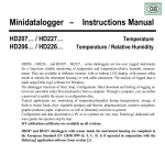
PARTS SUPPLIED
OPTIONAL FUNCTIONS
- AL2SW24 power supply unit
- Bracket and screws to fix power supply unit
- 2 x 47KOhm + 2 x 4K7 Ohm for NF1002 panel only
- 4 x 47KOhm + 6 x 4K7 Ohm for NF1004 and NF2000 panels
- Tecnical and programming manual
- User manual
- CD-Rom with documentation and configuration software
- Output for fire devices (GSM, Sounders)
- Outputs delay (DAY / NIGHT mode)
- Fault signal from points (NF2000 only)
- Correlation of alarm signals (Type A and B detection check)
- Unavailability of addressable points (Disablements devices, output modules, acoustic devices - NF2000 only)
- TEST condition (Test zones, outputs, loop outputs, loop
sounders, display, LED, buzzer)
3
090040786 - NF1002 - NF1004 - NF2000 - Technical and Programming Manuals
2. TECHNICAL FEATURES
Models
IP protection rate
Power supply
Nominal voltage frequency
Ripple
Max current drawn from mains
Max current drawn by panel (with
optional boards) and external loads
Normal operating range
Power consumption: idle status
Idle voltage of power supply unit’s
power supply
Idle voltage for battery power supply
Voltage for battery recharge
Voltage for battery disconnection
Current for battery recharge
Battery internal resistance (max)
Circuit for battery disconnection
Output voltage at AL. REL terminals
Available current at AL. REL
terminals
Output available current at
OUT+24V terminals
Current supplied by the power unit
NFEXP10 max power consumption
NFEXP20 max power consumption
EXTING max power consumption
MDGSME max power consumption
NFREL24 max power consumption
Connectors on main board
Connection terminal boards
on main board
Front displays
Front panel indicators
Functional keys
Zones
Supported devices
Operating temperature
Recommended batteries
Dimensions
Weight
Housing protection class
NF1002
NF1004
30
AC230V - +10% / -15%
50 Hz
102 mV (0,37%)
650 mA
NF2000
1,4 A
DC20V to DC30V
40mA
30mA
80mA
DC29V
DC26.6V
DC27.6V
18V
600mA
2,2 Ohm (7Ah)
1,5 Ohm (17Ah)
P10 jumper to control battery disconnection circuit operating mode
OPEN = disconnection at 18,2V voltage
CLOSED = no disconnection and RE-ARM (non compliant with EN54-4 standard)
DC27.6V
650mA max
2,2 Ohm (7Ah)
650mA max
2A max
-----
165 mA
500 mA
75mA
110 mA
40 mA
PRESETS
1 power supply unit, 2 RS-485, 1 GSM module, 2 EXPANSION boards,
1 USB, 1 MINI-DIN
2 AUX, 1 Fault, 1 Alarm, 1
2 AUX, 1 Fault, 1 Alarm, 1 Pre alarm, 2 x DC 24V,
Pre alarm, 2 x DC 24V,
1 RS-485, 2 NTC, 4 ZONE
1 RS-485, 2 NTC, 2 ZONE
Graphic LCD display - Color backlighting
LED indicators
YES
12 conventional
2 conventional
4 conventional
+ 32 An.In.
--254 over LOOP
-5°/+40° 93% r.h.
12V - 7Ah
12V - 17Ah
320 X 304 X 83 mm
390 X 390 X 99 mm
4 Kg
6 Kg
IP 30
4
Technical and Programming Manuals - NF1002 - NF1004 - NF2000 - 090040786
3. DIMENSIONS AND INSTALLATION
Panels dimensions are expressed in millimeters and the positioning of the fixing holes on the bottom of the housing are to be reported
on the wall. We recommend users to adopt screws and dowels suitable to support the panels weight in order to avoid any detachment
of the housings from the wall or the surface to which the panels is to be fixed.
After having drilled the holes, remove the front cover by unscrewing the 4 fixing screws (see following drawing.) You will have access
to the panel console and its main board; now, unscrew the two upper screws and rotate the panel forward, where the keypad and board
are fixed. Now the 3 (NF1002-NF1004) and 4 (NF2000) internal fixing holes will be visible and accessible, and it will be possible to fix
the panel to the wall or to the chosen support.
5
090040786 - NF1002 - NF1004 - NF2000 - Technical and Programming Manuals
6
Technical and Programming Manuals - NF1002 - NF1004 - NF2000 - 090040786
4. PANEL CONNECTORS AND WIRINGS
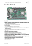
4.1 Main board view
After having rotated the plate supporting the display downwards (valid for every control unit model of this series), you will access the
back part of the panel main board. On its surface you will find the terminals and connectors to which the components are to be wired:
detectors, optional boards, power supply cables and all the devices necessary for a correct operation.
PANEL
MAIN BOARD
P10
P10 = RE-ARM
OPEN jumper = battery disconnection at 18,2V voltage
CLOSED jumper = no disconnection; yes RE-ARM
(non compliant with EN54-4 standard)
Picture 5
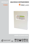
4.2 Main board connectors
Picture 6
7
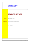
090040786 - NF1002 - NF1004 - NF2000 - Technical and Programming Manuals
Picture 7
8
Technical and Programming Manuals - NF1002 - NF1004 - NF2000 - 090040786
Picture 8
Picture 9
9
090040786 - NF1002 - NF1004 - NF2000 - Technical and Programming Manuals
NOTE: ETHERNET MDLAN module is not compliant with EN-54 standard.
S3
S2
MINIDIN
connector for PC
USB connector
Picture 10
S2 JUMPER indicated by the red arrow above indicates the sound power of the BZ1 BUZZER:
- S2 INSERTED = volume HIGH
- S2 NOT INSERTED = volume LOW
In order to ensure compliance with EN 54-2 standard, during panel normal operating mode, JUMPER S2 shall
be INSERTED and in case of alarm event the BZ1 BUZZER shall sound with high volume.
DO NOT TOUCH S3 JUMPER illustrated in Picture 10. LEAVE IT "ALWAYS ARMED".
Panels equipped with firmware v.2.0.x (or above) can be configured also using the PC connected with CP8/SER2
cable to the MINIDIN connector as indicated in the above diagram. CP8/SER2 cable shall be purchased separately.
The software can be installed using the CD-Rom supplied.
For the relevant documentation with installation instructions and software details see the files on the CD-ROM
provided (PDF format files in Documents folder.)
10
Technical and Programming Manuals - NF1002 - NF1004 - NF2000 - 090040786
4.3 NFEXP10 zones expansion board (NF2000 panel only)
Connected via RS-485 to the control unit, NFEXP10 expansion board allows to create groups of 8 conventional
zones, in addition to the 4 ZONES already provided by the panel. Such configuration allows to connect one
NFEXP10 board only, so that a total of 12 conventional zones will be achieved ( 4 on main board + 8 on NFEXP10
board = 12 CONVENTIONAL ZONES.)
• View of NFEXP10 expansion board:
Picture 12
The wiring of detectors and push buttons to the terminal on lower side of the board are similar and operate as
the ones of the 4 conventional ZONES already on the control panel. Consequently, electrical wirings must be performed as illustrated in the diagram in picture no. 14.
When the module is connected to the panel via RS-485 serial line (see picture no. 8) the system will set automatically for acknowledging and naming the new 8 zones. For example, if a NFEXP10 module is installed, you
will have the usual 4 zones (Z001 to Z004) on the main board, and the new 8 zones will be named from Z005 to
Z012. The RS-485 connection cable will allow to power the module.
It is important to remember that the address must be 0. It will have to be assigned to the module before its installation; for such operation, use the BOARD ADDRESS SELECTOR (see picture no.12).
• Example of positioning and installation of a NFEXP10 module:
Picture 12a
On the panel base there are the fixing holes where the plastic small supports shall be placed.
11
090040786 - NF1002 - NF1004 - NF2000 - Technical and Programming Manuals
For further details on installation, see the relevant Technical Manual.
IMPORTANT NOTE
To perform all the terminal wirings required (detectors, etc.) we recommend the use of CS/AI5 series cable as
lab tests have already been carried out and the following lengths determined:
CS/A50.5 cable
2x0,5mmq max length 500m
CS/AI51.5 cable
2x1,5mmq max length 1500m
CS/AI51 cable
2x1mmq max length 1000m
CS/AI52.5 cable
2x2,5mmq max length 2000m
4.4 Wiring of conventional detectors and call-points
These fire detection panels are preset for the connection of conventional devices connectable to the main board
( Zones from 001 to 004 - terminals from LIN.1 to LIN.4) or to NFEXP10 expansion boards (Fig. 12); to each zone
is associated a line that can be set according to needs, I/O inputs (balanced input, 4-20 mA input, PULL-UP input,
open collector output, see picture 15). The connection of the detectors and call-points to such zones is performed through the screw terminals placed on the main board fixed on the rear of the front panel, and access is
possible by rotating the fixing plate of the main board downwards (see pictures 3, 4, and 5) or on NFEXP10
expansion boards (see picture 13).
Please note that since ZONES are supervised, it will be necessary to apply 4700 Ohm resistances to the terminals
if zones are not used.
4.4.1 Detectors wiring diagram
Below are the diagrams of connections and types of connectable detectors; we will refer to the terminal of one
conventional zone only, reminding users that the 4 zones on the main board and the 8 zones on NFEXP10 module
are to be connected in the same way.
For further settings and detector / call points wiring procedure, please see the products’ technical manuals.
12
Technical and Programming Manuals - NF1002 - NF1004 - NF2000 - 090040786
Picture 14
Picture 14b
13
090040786 - NF1002 - NF1004 - NF2000 - Technical and Programming Manuals
4.4.2 Call-points wiring diagram
Below is the example wiring diagram of a call-point; we will refer to the terminal of one conventional zone only,
reminding users that the 4 zones on the main board and the 8 zones on NFEXP10 module are to be connected in
the same way.
The diagram shows an example of how to connect a BRVEN2 call-point: unlike the following examples (picture
15 and 16), the connection of this call-point does not require a 1000Ohm ALARM resistor connected in series
to the contact because the use of BRVEN2 call-point ’R’ terminal require the previous connection of a 880Ohm
resistor inside the call-point connected in series to the NO contact. The resistor also ensures the correct power
supply to the front LED indicator.
Please remind that ZONES are supervised, and when they are not used for the system a 4700 Ohm resistor shall
be connected to the terminals.
For further settings and wirings, please see the products’ technical manuals.
14
Technical and Programming Manuals - NF1002 - NF1004 - NF2000 - 090040786
Picture 14a
15
090040786 - NF1002 - NF1004 - NF2000 - Technical and Programming Manuals
4.4.3 I/O Terminals wiring diagram
Below is the diagram of I/O terminals wiring examples. The diagram refers to the 4 panel zones and the 8
NFEXP10 module zones.The operating mode will be dealt with in consultare il capitolo. “FIRE PANEL CONFIGURATION” a pag. 41.
Please remind that I/O ZONES are supervised, and when they are not used for the system a 47000 Ohm resistor
shall be connected to the terminals.
For further settings and wirings, please see the products’ technical manuals.
Picture 15a
16
Technical and Programming Manuals - NF1002 - NF1004 - NF2000 - 090040786
Selection: 4-20mA input
Picture 15b
Selection: Open collector output
Picture 15c
Selection: PULL-UP input
Picture 15d
17
090040786 - NF1002 - NF1004 - NF2000 - Technical and Programming Manuals
4.4.4 Additional line wiring diagram
On the main board there is an additional balanced line ( Z000 ) to which conventional call points can be wired.
The diagram below shows a different way of wiring BRVEN2 call point. Here the ’R’ terminal is not used and no
resistor is connected between the call point C and NO contacts. Instead, a 1000 Ohm resistor will be used and
connected in series to one of the two lines in order to operate as ALARM resistor and limit power supply to the
call point front LED.
Please remind that when they are not used for the system a 4700 Ohm resistor shall be connected to the terminals.
For further settings and wirings, please see the products’ technical manuals.
Picture 16
18
Technical and Programming Manuals - NF1002 - NF1004 - NF2000 - 090040786
4.5 Wiring diagram of AL.REL. supervised output with PTC protection
The terminal board features a supervised alarm output; such output supports the wiring of optical / acoustic devices that will be triggered in case of panel alarm events.
As it is a supervised output, do connect a 4700 Ohm balancing resistor to the end of the connecting cable. The
maximum current draw allowed is 650mA. The output is PTC-protected: it will start operating in case the current
draw gets too high. It will be also necessary to connect a 1N4007 diode in series to the POSITIVE contact of the
alarm relay in order to avoid damaging the bell during the supervision.
Please remind that when they are not used for the system a 4700 Ohm resistor shall be connected to the terminals.
For further settings and wirings, please see the products’ technical manuals.
Picture 17
4.6 Wiring diagram of the DC 24V power output with PTC protection
This is a PTC-protected DC 24V output and it is used when it is necessary to power devices requiring DC 24V
external power ( optical / acoustic alarm devices, detection devices, etc.) The output is PTC-protected: it will start
operating in case the consumption gets too high. The maximum current draw allowed is 650mA.
For further settings and wirings, please see the products’ technical manuals.
Picture 18
19
090040786 - NF1002 - NF1004 - NF2000 - Technical and Programming Manuals
• Connecting a SA100/24 siren to the ’OUT +24’ output: wiring diagram
For further settings and wirings, please see the products’ technical manuals.
Picture 18a
4.7 Wiring diagram of the DC 24V resettable power output with PTC protection
As the output seen at the previous paragraph, this too is a PTC-protected DC 24V output used when it is necessary to power devices requiring DC 24V external power supply. What is peculiar to this output is that it is possible
to cut the power supply when resetting the fire panel: the output will disable during reset procedure and re-enable
once the procedure is over. Such property allows to reset also connected devices that need to be reset.The maximum current draw allowed is 650mA.
For further settings and wirings, please see the products’ technical manuals.
Picture 19
20
Technical and Programming Manuals - NF1002 - NF1004 - NF2000 - 090040786
• ’+24RES.’ terminals wiring diagram
Example wiring diagram of ’+24 RES.’ and panel FIRST ZONE ’LIN.1’ terminals to two standard smoke barriers.
For further settings and wirings, please see the products’ technical manuals.
AS2/100
INT8C UNIVERSAL INTERFACE wirings
+24V RES.
terminal
24V
RESETTABLE power line
GND
NO
FAULT
relay
C
NC
1000
Ohm
NO
ALARM
relay
ZONE line
C
NC
4700
Ohm
Zone 1 / 4
terminal
ES50
BOARD internal wirings
Zone 1 / 4
terminals
RNA
RARA+
RERE+
1000
Ohm
ZONE line
4700
Ohm
LOOPLOOP+
0V
0V
+24V
RESETTABLE power line
+24V RES.
terminals
Picture 19a
4.8 Fault output wiring diagram
This is a free-from-potential NC-C-NO relay output that changes its status in case of panel fault events. The fault
events will be indicated on the front display too: the backlight will turn to yellow and the event will appear on the
display as a text string.
For further settings and wirings, please see the products’ technical manuals.
NOTE: in order to comply with EN 54-2 standard, the above outputs shall not be used to control alarm devices,
fire alarms and fault events transmission devices, or automatic systems since they are not "C", "E", "J" or "G"
type and therefore are not protected against cuts and short circuits.
21
090040786 - NF1002 - NF1004 - NF2000 - Technical and Programming Manuals
4.9 AUX 1 and AUX 2 programmable outputs wiring diagram
These are free-from-potential NC-C-NO outputs with independent and programmable relays; the outputs will
change status when the event they have been associated to occurs.
The diagram below shows the wiring of a inactive optical/acoustic device to AUX2 output C-NO contact and the
connection of a port magnetic retainer (that keeps ports open) to AUX1 output C-NC contact while the panel is
in normal operating mode (= no alarms occurrence.) The maximum load is 500mA per contact.
For further settings and wirings, please see the products’ technical manuals.
Picture 21
4.10 Pre-alarm output wiring diagram
This is a free-from-potential NC-C-NO relay output that changes its status when a pre-alarm event occurs. The
output is to be used to signal and/or display the panel pre-alarm condition or to make preset devices carry out
procedures in case of approaching alarm events. The maximum load that can be applied is 500mA.
For further settings and wirings, please see the products’ technical manuals.
NOTE: in order to comply with EN 54-2 standard, the outputs shall not be used to control alarm devices, fire alarms and fault events transmission devices, or automatic systems since they are not "C", "E", "J" or "G" type and
therefore are not protected against cuts and short circuits.
22
Technical and Programming Manuals - NF1002 - NF1004 - NF2000 - 090040786
4.11 RS-485 output for external keypads (NFREPEATER v.4.0.0 and above)
Up to 2 remote keypad (NFREPEATER) can be connected to RS-485 TAST. terminals. Keypads are to be installed
outside the panel.
The keypads will have the same operating mode as the central one: when the LEVEL 2 is selected (with the selection key) at one of the three keypads, the other keypads will automatically be inhibited until the selection key
is released and the LEVEL 1 selected again.
The data will be exchanged over RS-485 line and the wired keypads will be powered by the same line.
For further settings and wirings, please see the products’ technical manuals.
Picture 23
4.12 Batteries NTC inputs
Connect 2 NTC to these inputs: their bulbs have to be approached to the two rechargeable back up batteries;
these will have to be connected to the fire panel main board. The NTC will keep the temperature of the two batteries under control, since they are constantly connected with the internal battery charger that controls its functionality and keeps the correct charge level.
NTC BATTERIES
terminals
Picture 24
23
090040786 - NF1002 - NF1004 - NF2000 - Technical and Programming Manuals
4.13 Power supply units wirings
On the main board of the control panel there is a connector that supplies power to the panel. Only one power
supply unit is provided with the control panel: EXT1 POW. that supplies 2A current max.
We strongly recommend to verify the total power consumption of the fire panel previously, by calculating the total
amount of current required by the devices connected.
If a greater amount of current is required or it is necessary to grant 72h panel autonomy, it is available an additional connector (next to ALIM.EXT1 connector) with two RED/BLACK wires welded to the board: to such connector can be connected one or more DC 24V optional power units.
TO
AC230V
MAINS
Picture 25
4.14 Back up batteries wiring diagram
The current regulation provides for rechargeable batteries to be mounted on fire detection panels in order to supply power to the panels in case of mains failure events for a time fixed by the same regulation. After having removed the front panel of the fire unit (see picture 3) you will have access to the lower area of the panel housing.
The two 12V rechargeable batteries have to be connected with suitable amperage, using the two pairs of RED
and BLACK cables directly welded on the main board and coming from the display (see picture 4). Each cable
has to be connected to a battery; panel batteries will be placed on the lower area of the panel. The main board
will manage batteries operating status through the constant control of the charge and the temperature (see picture
24), and will activate their intervention in case of power/mains failure.
These batteries are not supplied with the panel and have to be purchased separately according to the panel type.
24
Technical and Programming Manuals - NF1002 - NF1004 - NF2000 - 090040786
Picture 26
4.15 MDGSME GSM module (optional)
MDGSME is a GSM module that connects to the main board and allows to send preset SMS messages to telephone numbers memorized in the control panel by inserting a SIM CARD. Once connected to the panel, the module is automatically acknowledged and its functions enabled. The GSM module is supplied with a cable that
allows to use the connector for the fixing of an external antenna (optional). Cable code is GSMAC90.
If the panel has been installed in areas where the GSM signal is weak, it is possible to connect a 15m optional
cable (GSMEXA15) to the external connector of the panel housing; the cable will allow to connect the antenna
outside the building or the area where the panel is installed.
If the panel has been installed in areas where the GSM signal is standard, it is possible to use a 2m optional
cable (GSMEXA2) to install the antenna closer to the panel. If you want to install the antenna directly on panel
housing, use GSMACI kit. The kit consists of an L-shape bracket and fixing accessories.
MDGSME
module
Picture 28
25
connector
For further settings and wirings, please see the products’ technical manuals.
090040786 - NF1002 - NF1004 - NF2000 - Technical and Programming Manuals
4.16 NFREL24 relay module (optional)
NFREL24 is a relay board that can be connected to the panel using a 10-way cable that allows its power supply
and control.
This module enables the panel to manage, when necessary, 4 additional relay outputs, moving to the terminals
the corresponding contacts.
Connecting the module to the panel with no further settings (default), all four module relays will activate upon
FIRE events.
On the contrary, if you proceed with further settings and access LEVEL 3 of panel configuration, it will be possible
to configure each output to activate upon a special event (see paragraph consultare il capitolo. “Output line” a
pag. 55.)
The max. applicable current is 500 mA per contact.
For further settings and wirings, please see the products’ technical manuals.
Picture 29
Picture 29a
26
Technical and Programming Manuals - NF1002 - NF1004 - NF2000 - 090040786
4.17 EXTING Extinguishing module (optional - only v. 3.0.0 and above)
EXTING optional module, duly connected and configured, ensures to the panel the possibility to extinguish a fire
automatically, using powders or foam.
The module can be installed inside NF1002, NF1004, and the two models of NF2000 panels (see image below);
on the front labels there are already all the indications for the signalling LEDs and the control buttons of the module.
The NF2000 series fire panels support the connection of only ONE extinguishing module connected as per following image.
The module is connected to the main board via a 4-wire cable through which the module is also powered and
receives the control signals over RS-485 line.
The panel will consequently control the extinguishing module directly and receive and display messages and signals the module transmits to the panel.
Similarly to other modules, also EXTING module, once connected to the panel, will be acknowledged automatically and can be configured as required.
EXTING module can be managed by panels version 3.0.0 or above.
For further settings and wirings, please see the products’ technical manuals.
EXTING
Extinguishing Module
( OPTIONAL )
PANEL
MAIN BOARD
27
090040786 - NF1002 - NF1004 - NF2000 - Technical and Programming Manuals
4.18 NFEXP20 - 1 AS LOOP Module (only NF2000 panel v.2.0.0 and above)
NFEXP20 module allows to add to the panel one AS LOOP for analogue-addressable devices. It allows to connect
and manage up to 254 addressable devices connected to the LOOP. Such devices can be distributed over 32
additional zones. NF2000 panel will then be able to manage 4 conventional zones on the main board + 8 conventional zones on NFEXP10 board + 32 analogue-addressable zones on NFEXP20 board.
For further settings and wirings, please see the products’ technical manuals.
Picture 32
The following operations must be carried out only by qualified technicians and with system and devices disconnected from power supplies.
1 - Install the expansion board to the panel base
Insert the two M3 screws supplied through the two holed hinges on the two sides of the plastic case; then fix it
to the base with washers and nuts.
2 - Wire NFEXP20 module to the NF2000 series panel main board
For such wiring the 6-way cable supplied with NFEXP20 kit shall be used. Connected it to the panel RS485 6way male connector (position A on picture 32 or 8) and to the NFEXP20 module 6-way male connector (position
B on picture 32.) The cable allows the communication of RS485 serial signals between panel and module; it also
allows module power supply.
3 - Connect FX-SNUBBER filter
The filter is supplied with the kit and will improve immunity against electromagnetic noise.
The NFEXP20 module features an hexagonal metal self-tapping support to which has to be fixed one of the eyelet
terminals of the filter yellow/green cable with one of the two M3 screws (and the washer) supplied with the kit (
A ) The other end of the yellow/green cable has to be fixed to the panel base ( B ) using the second screw; use
one of the available holes and fix the eyelet terminal using nut and washers or the self-tapping screw.
28
Technical and Programming Manuals - NF1002 - NF1004 - NF2000 - 090040786
Once the two filter cable ends have been fixed, secure the filter case to the panel base using both-sides-adehesive
tape and plastic clamps as illustrated in the following picture:
Picture 32a
WARNING
For the proper module operation,
all the dipswitch must be in OFF.
4.18.1 NFEXP20 module EARTH wiring
The module bottom area ( picture 32a, position C ) features a male FASTON terminal welded to the printed circuit.
To such male terminal has to be connected the insulated female FASTON terminal supplied with NFEXP20 module.
The other end of the cable ( picture 32a, position D ) will be partially non-insulated in order to allow its connection
to the screw terminal of the panel EARTH wiring.
• NFEXP20 LED indicators: name, colour and function
Picture 32b
LED Name
Colour
Status OFF
Status
BLINKING
Status ON
POWER
Green
No Power
---
Power OK
POLLING
DEVICE
Green
No
Communicatio
n to Devices
Communicatio
n OK
---
POLLING
PANEL
Yellow
No
Communicatio
n to Panel
Communicatio
n OK
---
-- L --
Yellow
’L’ line
short-circuited
LOOP open
OK
-- R --
Yellow
’R line
short-circuited
LOOP open
OK
29
090040786 - NF1002 - NF1004 - NF2000 - Technical and Programming Manuals
4.18.2 AS LOOP standard diagram
Picture 32c
30
Technical and Programming Manuals - NF1002 - NF1004 - NF2000 - 090040786
4.18.3 Analogue-addressable devices wired to the the panel loop
• ST-NCP-EN2 call-point wiring diagram
For further settings and wirings, please see the product technical manual.
Picture 32d
• UB-4 bases wiring diagram
Connection of two UB-4 bases.
Picture 32e
31
090040786 - NF1002 - NF1004 - NF2000 - Technical and Programming Manuals
4.18.4 Table of NFEXP20 module compatible AS devices
PRODUCT CODE
PRODUCT DESCRIPTION
ISOBASE
(SCI3)
Line isolator module that can be installed on the detector’s base, for disabling part of the loop in
case a short-circuit occurs whilst normal operation is continued on remaining equipment. We
recommend installing an isolator every 32 detectors/addresses. DC24V power supplied by the
loop. It will replace SCI3.
ISOBOX
(SCI4)
Line isolator module for disabling part of the loop in case a short-circuit occurs whilst normal
operation is continued on remaining equipment . We recommend installing an isolator every 32
detectors/addresses. Suplied with plastic case. DC24V power supplied by the loop. It will replace
SCI4.
ISOSPLITAS
Module allowing the connection of 2 separate loops to the same AS loop board. DC24V power
supplied by the loop.
1IASBOX
Analogue-addressable module with ONE balanced / not balanced input to signal alarm and fault
alerts (line open / shortcircuited); it allows to connect ONE detector (or other conventional devices)
featuring NO output relay contacts to a detection loop. Unit addresses set via rotary switch. DC24V
power supplied by the loop. Reduced-size plastic case. (Performance certificate no. 0051-CPR0276, standard EN54-18.)
4IASBOX
Analogue-addressable module with FOUR balanced / not balanced input to signal alarm and fault
alerts (line open / shortcircuited); it allows to connect FOUR detectors (or other conventional
devices) featuring NO output relay contacts to a detection loop. Unit addresses set via rotary
switch. Terminal board for NO inputs, external LED indicator and serial loop connection. Equipped
with line isolator. DC24V power supplied by the loop. Reduced-size plastic case. (Performance
certificate no. 0051-CPR-0274, standards EN54-18 and EN54-17.)
1OASBOX
Analogue-addressable module with ONE bistable relay output (C-NO-NC) with 2A/DC30V carrying
capacity. Module used to control acoustic, optical-acoustic and other devices with power supplied
by external power units. Unit addresses set via rotary switch. Terminal board for external LED
indicator, relay output, and serial loop connection. DC24V power supplied by the loop. Reducedsize plastic case.
(Performance certificate no. 0051-CPR-0276, standard EN54-18.)
4OASBOX
Analogue-addressable module with FOUR bistable relay outputs (C-NO-NC) with 2A/DC30V
carrying capacity. Unit addresses set via rotary switch. Terminal board for external LED indicator,
relay outputs, and serial loop connection. Equipped with line isolator. DC24V power supplied by
the loop. Reduced-size plastic case. (
Performance certificate no. 0051-CPR-0274, standard EN54-18 and EN54-17.)
1I1OASBOX
Analogue addressable module with ONE input and ONE output; the input is balanced / not balanced
for alarm and fault alerts (line open / shortcircuited). The module allows to connect 1 detector (or
other conventional devices) featuring NO output relay contacts to a detection loop. Unit addresses
set via rotary switch . DC24V power supplied by the loop. Terminal board for NO inputs, external
LED indicator, relay output, and serial loop connection. 1 bistable relay output (C-NO-NC) with
2A/DC30V carrying capacity used to control acoustic, optical-acoustic and other devices with
power supplied by external power units. Reduced-size plastic case. (Performance certificate no.
0051-CPR-0276, standard EN54-18.)
2I1OASBOX
Analogue addressable module with TWO inputs and ONE output; inputs are balanced / not
balanced for alarm and fault alerts (line open / shortcircuited). The module allows to connect 2
detectors (or other conventional devices) featuring NO output relay contacts to a detection loop.
Unit addresses set via rotary switch . DC24V power supplied by the loop. Terminal board for NO
inputs, external LED indicator, relay output, and serial loop connection. 1 bistable relay output
(C-NO-NC) with 2A/DC30V carrying capacity used to control acoustic, optical-acoustic and other
devices with power supplied by external power units. Reduced-size plastic case.
(Performance certificate no. 0051-CPR-0276, standard EN54-18.)
4I4OASBOX
Analogue addressable module with FOUR inputs and FOUR outputs; inputs are balanced / not
balanced for alarm and fault alerts (line open / shortcircuited). The module allows to connect 4
detectors (or other conventional devices) featuring NO output relay contacts to a detection loop.
Unit addresses set via rotary switch. Terminal board for NO inputs, external LED indicator, relay
output, and serial loop connection. 4 bistable relay outputs (C-NO-NC) with 2A/DC30V carrying
capacity. Equipped with line isolator. DC24V power supplied by the loop. Reduced-size plastic
case. (Performance certificate no. 0051-CPR-0274, standard EN54-18 and EN54-17.)
32
Technical and Programming Manuals - NF1002 - NF1004 - NF2000 - 090040786
PRODUCT CODE
PRODUCT DESCRIPTION
1D1IASBOX
Analogue addressable module for 1 door control. The module features 2 balanced inputs and 1
output, all associated to receive signals from devices or detectors for the control of a door or a
fire barrier door and to control their closing with its relay output. The module features also a
balanced / not balanced input for alarm and fault alerts (line open / shortcircuited). The module
allows to connect 1 detector (or other conventional devices) featuring NO output relay contacts
to a detection loop. Unit addresses set via rotary switch.
3-terminal C-NC-NO bistable relay output (2A at DC30V). DC24V power supplied by the loop.
Reduced-size plastic case. (Performance certificate no. 0051-CPR-0276, standard EN54-18.)
1DASBOX
Analogue addressable module for ONE door control. The module features 2 balanced inputs and
1 output, all associated to receive signals from devices or detectors for the complete control of a
door or a fire barrier door and to control their closing with its relay output. Unit addresses set via
rotary switch. 1 bistable relay output (C-NO-NC) with 2A/DC30V carrying capacity. DC24V power
supplied by the loop. Electromagnet powered by external power unit. Reduced-size plastic case.
(Performance certificate no. 0051-CPR-0276, standard EN54-18.)
2DASBOX
Analogue addressable module for TWO doors control. The module features 4 balanced inputs
and 2 outputs, all associated to receive signals from devices or detectors for the complete control
of 2 doors or 2 fire barrier doors and to control their closing with its relay output. Unit addresses
set via rotary switch. Bistable relay outputs (C-NO-NC) with 2A/DC30V carrying capacity.
Electromagnet powered by external power unit. Equipped with line isolator. DC24V power supplied
by the loop. Reduced-size plastic case.
(Performance certificate no. 0051-CPR-0274, standard EN54-18 and EN54-17.)
4DASBOX
Analogue addressable module for FOUR doors control. The module features 4 balanced inputs
and 4 outputs, all associated to receive signals from devices or detectors for the complete control
of 4 doors or 4 fire barrier doors and to control their closing with its relay output. Each control
relay output is associated with a single input which manages door closed status. Unit addresses
set via rotary switch. 3-terminal C-NC-NO bistable relay output (2A at DC30V). Equipped with line
isolator. DC24V power supplied by the loop. Reduced-size plastic case. (Performance certificate
no. 0051-CPR-0274, standard EN54-18 and EN54-17.)
MCM-AS3B
Control and monitoring module to be connected to the detection loop. The module is used to
supervise 20 ST-P conventional detectors or 5 NFD/68P flame detectors. Unit address is set via 8
dip-switches. The module features 2 outputs: 1 open-collector output (10mA at 24V DC), and 1
C/NC/NO relay output (2A at 30V DC.) It can be housed in BOX1 case. DC24V power supplied
by the loop. (NO IMQ-SISTEMI DI SICUREZZA certified.)
SCM-AS2B
Module for acoustic alarm devices control to be connected to the detection loop. The module
features inputs for local silencing buttons, SYNC type inputs, and for external power supply power
drop. It also features 1 supervised output for acoustic devices (1A max. current draw). Unit address
is set via 8 dip-switches. It can be housed in BOX1 case. DC24V power supply required. (NO IMQSISTEMI DI SICUREZZA certified.)
NAM-AS-G
Analogue addressable interface to connect a 4-20mA gas detector to an analogue addressable
detection loop. Detector’s operating parameters can be monitored and operating thresholds set.
Connectable detectors: TS910EC-S and TS220EC-S for carbon dioxide detection; TS293KG
andTS292KG for GPL detection; TS293KM and TS292KM for methane detection. Unit address set
via 8 dip-switches. Unit can be housed in BOX3 (optional) IP56. DC24V power supply required.
(NO IMQ-SISTEMI DI SICUREZZA certified.)
MTB
Analogue addressable unit for local alarm, can be connected to pull-cord switches, “pull-cord
alarms” or for room calls. Unit address set via 8 dip-switches. Dimensions W59 x H40 x D15mm.
DC24V power supplied by the LOOP. (NO IMQ-SISTEMI DI SICUREZZA certified.)
AS-ABS
Sounder module for analogue LOOP. It can be installed individually to an analogue loop with VCT03CPR red cover (optional), or can be mounted on to a STB-4 analogue-addressable detector
base (optional.) Sound pressure: 91dB (4 tones.) Unit address set via 8 dip-switches. DC8-35V
power supplied by the loop.
(NO IMQ-SISTEMI DI SICUREZZA certified.)
UB-4
Standard base for ST-P-AS, ST-H-AS, NHD-G2, 2SC-LS, and VCT-03NTAS detectors.
(NO IMQ-SISTEMI DI SICUREZZA certified.)
BOX1
IP55 case for modules. (NO IMQ-SISTEMI DI SICUREZZA certified.)
BOX2
Modules case. (NO IMQ-SISTEMI DI SICUREZZA certified.)
BOX3
IP56 case for modules. (NO IMQ-SISTEMI DI SICUREZZA certified.)
RFP-AS2B
Optical-acoustic alarm device for AS analogue-addressable loop. Can be directly connected to
the LOOP.
(NO IMQ-SISTEMI DI SICUREZZA certified.)
33
090040786 - NF1002 - NF1004 - NF2000 - Technical and Programming Manuals
PRODUCT CODE
PRODUCT DESCRIPTION
ST-PY-AS
Analogue-addressable smoke detector with Tyndall-effect based operation mode. Thresholds
adjustable during control panel’s setup. Alarm signal from OMNIVIEW360° luminous ring. Internal
automatic compensation for dust contamination. IP 42 protection class. Supplied without base.
Compatible base: UB-4. DC24V power supplied by loop. EN54-7 LPCB and CPD 89/106/EEC
certified. MTM-E detector address programmer required.
MTM-E
Programmer for ST-PY-AS detector address setup and identification. Detector address is set via
software from keypad by hooking the detector to the programmer. Shoulder belt included. Requires
2 batteries: 9V 6LF22, 6LR61 or MN1604 (not supplied.) (NO IMQ-SISTEMI DI SICUREZZA certified)
ST-NCP-EN2
Call point for analogue-addressable fire detection control panels. Manual alarm generated by
pressing the center of the front glass. Line isolator included. P24D indoor protection class. Case
open and panel reset key included. DC24V power supplied by loop.
(Performance certificate no. 0051-CPR-0309, EN54-11 and EN54-17 standards.)
ST-NCP-IP
Outdoor analogue-addressable glassbreak fire alarm call point. IP67 protection class. Features
film for protection against injuries, test key, and operating LED indicators. Internal dip-switch to
set addresses.
DC24V power supplied by loop. EN54-11 standard compliant. (NO IMQ-SISTEMI DI SICUREZZA
certified)
RFP-AS2B
Optical-acoustic repeater module directly connectable to AS analogue-addressable loops of fire
systems with no need of further control devices. Sounds and LEDs operating mode are useradjustable.
NO IMQ-SISTEMI DI SICUREZZA certified)
34
Technical and Programming Manuals - NF1002 - NF1004 - NF2000 - 090040786
5. INSTALLATION AND SETUP OF EXPANSION BOARDS
Following diagrams show the available configurations for all NF-series panels illustrated in this manual. They indicate the maximum number of expansion boards that can be wired to panels and boards position inside panel
housings.
5.1 NF1002 - NF1004 panels
These panels can be set as follows:
1 x Main Board of 2 - 4 zone panel
1 x MDGMSE GSM board
1 x AL2SW24 power unit
1 x NFREL24 relay module
1 x EXTING extinguishing module
• Block diagram of the system
• Board position inside panel housing
35
090040786 - NF1002 - NF1004 - NF2000 - Technical and Programming Manuals
5.2 NF2000 panel (12 conventional zones + 1 LOOP)
These panels can be set as follows:
1 x Main Board of 4-zone panel
1 x MDGMSE GSM board
1 x AL2SW24 power unit
1 x NFREL24 relay module
1 x NFEXP10 8-zone expansion module
1 x NFEXP20 loop module
1 x EXTING extinguishing module
• Block diagram of the system
• Boards position inside panel housing
36
Technical and Programming Manuals - NF1002 - NF1004 - NF2000 - 090040786
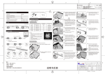
6. PANEL DISPLAYS AND KEYS
Below is the front label; all functions and states of the control panels are shown by and managed using the
graphic display and they are indicated by coloured LED indicators. The control keys of the many panel functions
make panel control and programming operations extremely easy and user-friendly.
One of the features of the new graphic display is the option of changing the backlighting colour according to the
status of the control unit. During normal operation, the display backlight will be GREEN, YELLOW in case of fault
or anomaly, RED in case of alarm events. When the control unit is being programmed or set, the backlight will
be WHITE.
Normal operation mode
GREEN
Alert for anomaly or wrong connection
YELLOW
Alarm alert
RED
Setup mode
WHITE
37
090040786 - NF1002 - NF1004 - NF2000 - Technical and Programming Manuals
6.1 Panel LED indicators
LED name
Colour
Indication
POWER
GREEN
230V Power
SILENCE
YELLOW
Acoustic devices silenced
PRE-ALARM
RED
Alarm check + pre-alarm ON
INVEST. DELAY
YELLOW
Acknowledgment timer or
Investigation timer active
DAY / NIGHT
YELLOW
Day / Night mode
LED name
Colour
Fixed Light
Blinking
FIRE
RED
Alarm event(s) ON with silenced sounder
Alarm events ON
GSM ON
RED
Telephone dialler ON
Waiting a confirm
DISABLE
YELLOW
Disabled elements
-----
TEST
YELLOW
System element(s) is / are being tested
-----
GENERAL FAULT
YELLOW
Fault events ON with silenced buzzer
Fault events ON
SYSTEM FAULT
YELLOW
CPU fault with silenced buzzer
CPU fault
SOUNDERS FAULT /
DISABLED
YELLOW
Sounders disabled
Sounders fault
GSM FAULT /
DISABLED
YELLOW
GSM disabled
GSM fault
38
Technical and Programming Manuals - NF1002 - NF1004 - NF2000 - 090040786
6.2 Panel function keys
Level 1 Function
Level 2 Function
Level 3 Function
----
Enters the selected menu /
Confirms data
Enters the selected menu /
Confirms data
Scrolls events UP
Moves the selection upwards
Moves the selection upwards
Scrolls events DOWN
Moves the selection
downwards
Moves the selection
downwards
Displays fault events, if at the
same time alarm events are
present
Returns to previous menu /
Delete operation
Returns to previous menu /
Deletes operation
Key name
Level 1 Function
Level 2 / 3 Function
EVACUATE
During panel acknowledgment
or investigation time it resets
panel delay time intervals and
sets the panel to alarm
condition
During panel idle status, it
generates an "evacuate" event and
sets the panel to alarm condition.
During panel acknowledgment or
investigation time it operates as
seen at level 1.
At level 3 the key is disabled.
SILENCE
Silences the buzzer
During panel alarm or fault
condition. it silences acoustic
devices.
If pressed again, it re-activates such
devices. During Day/Night mode
acknowledgment time it sets the
panel to investigation mode
RESET
-----
During panel alarm or fault
condition, it resets the panel.
DAY / NIGHT
-----
It enables / disables day/night
mode. At level 3 the key is
disabled.
To access LEVEL 2:
insert the special key supplied with the fire panel into the level
selector and rotate it: you will switch from LEVEL 1 to LEVEL 2.
To access LEVEL 3:
once at level 2, scroll the menu and insert a PASSWORD for
the PROGRAMMING section.
WARNING
To restore the alarm viewing, you must access to the Level 2 by turning the key and pressing the ESC button.
39
090040786 - NF1002 - NF1004 - NF2000 - Technical and Programming Manuals
Blank page
40
Technical and Programming Manuals - NF1002 - NF1004 - NF2000 - 090040786
7. FIRE PANEL CONFIGURATION
Before proceeeding with panels configuration, consider that there are different access levels (ref. EN54-2 standard and Appendix A.)
Access levels of these panel series are 4, and they allow to perform different functions.
LEVEL 1
LEVEL 2
LEVEL 3
LEVEL 4
UNRESTRICTED ACCESS
USER ACCESS
MAINTENANCE ACCESS
MANUFACTURER ACCESS
ACCESS LEVEL #1
This is the first access level. When the panel is switched on, it sets to LEVEL 1. This level has no restrictions and can be used for panel
general monitoring.
ACCESS LEVEL # 2
To access Level 2, insert the special key supplied with the fire panel into the level selector and rotate it from Level 1 to Level 2.
The level will be accessible for people with special responsibility (eg. building surveillance people.)
The level 2 allows the standard operating mode, that is, it will allow detecting alarms and faults.
To go back to Level 1, turn the key and set it to LEVEL 1.
If the panel is not used for 15 minutes (no operations performed and no keys pressed), the display backlight will start blinking and the
last line of the panel display will show the message: PANEL ON LEVEL 2.
If a key is pressed, the line will disappear for 15 minutes but the blinking will go on until the panel goes back to Level 1.
ACCESS LEVEL #3
Once at level 2, insert a 4-figure PASSWORD to access LEVEL 3.
Level 3 can be accessed only by authorized personnel trained to setup and verify panel status (eg. the installer.)
The installer can set up to 3 password for level 3 and for each password a descriptive string can be set.
Passwords can be changed if necessary; password characters will be hidden during digitation and a double confirmation is required.
To go back to level 2, press ESC key. The panel returns automatically to level 2 after a 5-minute timeout,
The timeout starts each time a key is pressed.
7.1 Level 2 menu
To access LEVEL 2 menu, insert the key supplied with the panel into the plastic lock on the front of the fire panel housing (seeconsultare
il capitolo. “Panel function keys” a pag. 39) then turn it and set it to LEVEL 2 position.
Display backlight will turn white and LEVEL 2 menu will be displayed as per following image.
Use ,, ENTER and ESC keys to browse Level 2 Menu.
Level 2 menu starting display:
= ENTER
= UP
= DOWN
Main selection
= ESC
Selected submenu
41
090040786 - NF1002 - NF1004 - NF2000 - Technical and Programming Manuals
7.1.1 Disablements
This menu displays lists of zones, devices, and modules that can be disabled, their current status and items
already disabled.
The display below is typical of this menu.
When on the right of an item the "x" symbol appears, it indicates that one (or more) of such item(s) is disabled
(see Output Modules in the example.)
For more details on the item(s) disabled, please enter the relevant submenu using the arrows and ENTER key.
Disablings
ZONE
One (or more) output
module(s) is disabled
Device
Output Modules
X
Sounders.
Panel Outputs
Disablements - ZONE
Go to LEVEL 2 MENU > DISABLEMENTS > ZONE
- A list of zones will display (zones displayed depends on panel model and setup)
- Use (UP) and (DOWN) keys to select the zone(s) to disable.
- To disable the zone selected press ENTER (an ’X’ will appear on the right).
- To re-enable the zone, press ENTER again (the ’X’ on the right will disappear).
- To go back to LEVEL 2 MENU, press ESC twice.
NOTE: when all the addressed devices connected to the same zone are disabled, such ZONE will appear as disabled in the menu above
("x" symbol on the right.) When such zone is re-enabled, all the addressed devices connected to such zone will be re-enabled.
Disablements - DEVICE (enabled if NFEXP20 - LOOP module is installed)
Go to LEVEL 2 MENU > DISABLEMENTS > DEVICE
- A list of the addresses of the self-learnt devices will be displayed.
- Use (UP) and (DOWN) keys to select the device (address) to disable.
- To disable the device selected press ENTER (an ’X’ will appear on the right).
- To re-enable the device, press ENTER again (the ’X’ on the right will disappear).
- To go back to LEVEL 2 MENU, press ESC twice.
Disablements - OUTPUT MODULES (enabled if NFEXP20 - LOOP module is installed)
Go to LEVEL 2 MENU > DISABLEMENTS > OUTPUT MODULES
- A list of the addresses of the output modules will be displayed.
- Use (UP) and (DOWN) keys to select the module (address) to disable.
- To disable the module selected press ENTER (an ’X’ will appear on the right).
- To re-enable the module, press ENTER again (the ’X’ on the right will disappear).
- To go back to LEVEL 2 MENU, press ESC twice.
42
Technical and Programming Manuals - NF1002 - NF1004 - NF2000 - 090040786
Disablements - SOUNDERS (enabled if NFEXP20 - LOOP module is installed)
Go to LEVEL 2 MENU > DISABLEMENTS > SOUNDERS
- A list of the addresses of the sounders will be displayed.
- Use (UP) and (DOWN) keys to select the sounder (address) to disable.
- To disable the sounder selected press ENTER (an ’X’ will appear on the right).
- To re-enable the sounder, press ENTER again (the ’X’ on the right will disappear).
- To go back to LEVEL 2 MENU, press ESC twice.
Disablements - PANEL OUTPUTS
Go to LEVEL 2 MENU > DISABLEMENTS > PANEL OUTPUTS
- The list of ZONES, AUX1 and AUX2 outputs, and SOUNDERS output will be displayed.
- Use (UP) and (DOWN) keys to select the output to disable.
- To disable the output selected press ENTER (an ’X’ will appear on the right).
- To re-enable the output, press ENTER again (the ’X’ on the right will disappear).
- To go back to LEVEL 2 MENU, press ESC twice.
Disablements - EXTINGUISHING MODULE
Go to LEVEL 2 MENU > DISABLEMENTS > EXTINGUISHING MODULE
- To disable the extinguishing module press ENTER (an ’X’ will appear on the right).
- To re-enable the extinguishing module, press ENTER again (the ’X’ on the right will disappear).
- To go back to LEVEL 2 MENU, press ESC twice.
Disablements - GSM
Go to LEVEL 2 MENU > DISABLEMENTS > GSM
- To disable the GSM module, press ENTER (an ’X’ will appear on the right).
- To re-enable the GSM module, press ENTER again (the ’X’ on the right will disappear).
- To go back to LEVEL 2 MENU, press ESC twice.
Disablements - REPEATER
Go to LEVEL 2 MENU > DISABLEMENTS > REPEATER
- To disable the REPEATER module, press ENTER (an ’X’ will appear on the right).
- To re-enable the REPEATER module, press ENTER again (the ’X’ on the right will disappear).
- To go back to LEVEL 2 MENU, press ESC twice.
43
090040786 - NF1002 - NF1004 - NF2000 - Technical and Programming Manuals
7.1.2 Events
Go to LEVEL 2 MENU > DISABLEMENTS > EVENTS
- The panel events log will be displayed.
- Use (UP) and (DOWN) keys to browse panel events.
- To go back to LEVEL 2 MENU, press ESC key.
Event date and time
Event type
Alarmed zone and device
Description
Event number / Total events
7.1.3 Devices (with NFEXP20 -LOOP installed)
Go to LEVEL 2 MENU > DEVICES
- The display will show the address of the first devices self-learn to the loop.
- Use (UP) and (DOWN) keys to browse registered addresses.
- Press ENTER to display the type of device connected to the address in use.
- Use (UP) and (DOWN) keys to browse memorized devices and display their:
Address - Type - Description - Zone - Group (if present)
- To exit press ESC key.
7.1.4 Test
This menu allows to test panel outputs and zones.
Test - ZONES
Go to LEVEL 2 MENU > TEST > ZONES
- The list of zones will be displayed (zones will be displayed according to panel model and setup.)
- Use (UP) and (DOWN) keys to select the zone to be tested.
- To start testing the zone selected, press ENTER (an ’X’ will appear on the right).
Now the zone has to be alarmed by triggering a detector or the zone emergency call point. The panel will trigger AL.REL. alarm
output signalling the detection of the sensor or the call point; it will disable the output after 10 seconds.
- To stop testing this zone, press ENTER again (the ’X’ on the right will disappear).
Test - OUTPUTS
Go to LEVEL 2 MENU > TEST > OUTPUTS
- Use (UP) and (DOWN) keys to select SOUNDER option.
- To enable SOUNDER (or AL.REL.) output, press ENTER (an ’X’ will appear on the right).
- To disable the output, press ENTER again (the ’X’ on the right will disappear).
- Use (UP) and (DOWN) keys to select ZONE 1 (valid for all zones connected).
- To enable ZONE 1 output, press ENTER (an ’X’ will appear on the right).
- To disable the output, press ENTER again (the ’X’ on the right will disappear).
[OUTPUTS are: relay outputs of optional NFREL24 board + digital outputs of panel I/O terminals, if setup]
44
Technical and Programming Manuals - NF1002 - NF1004 - NF2000 - 090040786
- Use (UP) and (DOWN) keys to select FAULT option.
- To enable FAULT output, press ENTER (an ’X’ will appear on the right).
- To disable the output, press ENTER again (the ’X’ on the right will disappear).
- Use (UP) and (DOWN) keys to select AUX 1 option.
- To enable AUX 1 relay, press ENTER (an ’X’ will appear on the right).
- To disable the relay, press ENTER again (the ’X’ on the right will disappear).
- Use (UP) and (DOWN) keys to select AUX 2 option.
- To enable AUX 2 relay, press ENTER (an ’X’ will appear on the right).
- To disable the relay, press ENTER again (the ’X’ on the right will disappear).
Test - LOOP OUTPUTS (with NFEXP20 -LOOP installed)
Go to LEVEL 2 MENU > TEST > LOOP OUTPUTS
- The list of addresses of output modules self-learnt to the loop will be displayed.
- Use (UP) and (DOWN) keys to select the address of the output to be tested.
- To enable the selected output, press ENTER (an ’X’ will appear on the right).
- To disable the output, press ENTER again (the ’X’ on the right will disappear).
- To exit test mode and go back to TEST menu press ESC key.
Test - LOOP SOUNDER (with NFEXP20 -LOOP installed)
Go to LEVEL 2 MENU > TEST > LOOP SOUNDERS
- The list of addresses of SOUNDERS modules self-learnt to the loop will be displayed.
- Use (UP) and (DOWN) keys to select the address of the module to be tested.
- To enable the selected sounder, press ENTER (an ’X’ will appear on the right).
- To disable the sounder, press ENTER again (the ’X’ on the right will disappear).
- To exit test mode and go back to TEST menu press ESC key.
Test - DISPLAY and BACKLIGHT
Go to LEVEL 2 MENU > TEST > DISPLAY
- A vertical bar will start displaying from the left side of the graphic display and will switch on all the pixels of the display.
- At the same time, the display backlight will change colour every second in sequencial mode.
- To exit test mode and go back to TEST menu press ESC key.
Test - LED
Go to LEVEL 2 MENU > TEST > LED
- The LEDs on the panel front cover will switch on for 2 seconds all at the same time.
- The panel will return to TEST menu after 2 seconds automatically.
Test - BUZZER
Go to LEVEL 2 MENU > TEST > BUZZER
- The panel buzzer will be enabled for 5 seconds.
- The panel will return to TEST menu after 5 seconds automatically.
45
090040786 - NF1002 - NF1004 - NF2000 - Technical and Programming Manuals
7.1.5 Display contrast
Go to LEVEL 2 MENU > DISPLAY CONTRAST
- Press (UP) and (DOWN) keys repetedly to increase / decrease the percentage of the displayed contrast.
- Press ENTER to save the new settings.
- Press ESC to exit without saving and go back to LEVEL 2 menu.
7.1.6 Programming
Go to LEVEL 2 MENU > PROGRAMMING
- Key-in the 4-figure PASSWORD (default 0000).
- Press (UP) and (DOWN) keys repetedly to increase / decrease a number.
- Press ENTER to move to the following figure.
- Once the fourth figure has been digited, and the password is correct, press ENTER to access LEVEL 3 menu.
46
Technical and Programming Manuals - NF1002 - NF1004 - NF2000 - 090040786
7.2 Level 3 menu
Items of level 3 menu: Version, Loop, Extinguishing unit, Peripherals, Zones, Panel Outputs, GSM, Network & Supervision, Logic Statements, Day/Night Mode, Delete Progr., Settings, Service Info, Cable Test.
7.2.1 Version
Go to LEVEL 3 menu > VERSION
- The panel firmware version will be displayed, and also the version of NFEXP20 loop module, NFEXP10 expansion board, and
EXTING and NFREPEATER modules.
- Press ESC key (or ENTER key again) to exit the menu.
7.2.2 Loop
Loop item will be available only if a NFEXP20 module has been installed on to the panel (see picture 32.)
This menu allows to set options and functions of all the analogue addressable devices connected to the NFEXP20 module, according
to the single device properties.
When the NFEXP20 is installed for the first time, only the SELF-LEARNING item will display.
- Go to SELF-LEARNING and press ENTER.
- All the analogue addressable devices connected to the loop and previously addressed and powered will be self-learnt.
For further setup and wirings data, please see the devices technical manuals.
When the self-learning procedure is over, a list of the detected devices will be displayed indicating also the quantity.
Now press ENTER and select:
YES + ENTER = to save the devices detected
NO + ENTER= to exit without saving
NOTE: the selected option is the one with the black background.
IMPORTANT : if the connected devices are not detected, the message ’NO DEVICE CONNECTED’ will appear.
Check power lines and wirings, then repeat self-learning procedure.
When the list of self-learnt devices is saved, two new items will be displayed under SELF-LEARNING menu: Devices Prog. and Loop
Restart.
>> Devices Programming
This menu allows to setup the options of all connected devices. The system acknowledges the type of connected devices automatically;
it will display the device and will enable / disable setup options that appear individually for each device in Devices Prog. menu.
- Use (UP) and (DOWN) keys to select DEVICES PROG. then press ENTER.
- The line ADDRESS will appear and will be followed by the first address self-learnt during self-learning procedure (ex. 001)
- Use (UP) and (DOWN) keys to browse all self-learnt addresses with a device currently connected (001,..., 254)
- To check the device that is connected to a specific address, move the selection to the address then press ENTER.
- The display that will appear will be similar to the following picture (call-point address 001, wired and self-learnt for the first time
to the loop):
Address
Device Type
Description
Zone
Address: device address.
I:001
Call Point
Reception
Z:013
Device type: type of device connected.
Description: 16-character max row for device details (ex: output,
reception, etc.)
Zone: zone to which the device is associated (default 013.)
47
090040786 - NF1002 - NF1004 - NF2000 - Technical and Programming Manuals
It is a new address, so the line DESCRIPTION will show no information and the zone to which it will be associated by default is no. 013.
To change zone number, just add text to the description line, or modify other parameters.
Th enter device setup section, press ENTER again.
The example above shows the connection of an analogue-addressable call point to a loop.
Options can be enabled according to the type of device connected.
The following table shows which options can be enabled for the various devices (and will therefore be displayed in the device setup
area):
Call
Point
Temper.
Detect.
GAS
Detect.
Smoke
Detect.
Output
Module
Input
Module
Zone
Module
Sounder
Zone
X
X
X
X
X
X
X
X
Description
X
X
X
X
X
X
X
X
X
X
Type
X
Sensitivity
X
Generated Event
X
Alarm Logic Event
X
Pre-alarm Logic Event
X
X
X
X
X
X
X
X
X
X
X
Activation Event
X
X
X
Logic Activation Event
X
X
X
Mode
X
Zone Group
X
X
X
Double Knock
X
X
X
LED Switch ON
X
X
X
X
Description of table options:
• Option: ZONE
Option to set the ZONE of the device.
Go to ZONE and press ENTER
- Use (UP) and (DOWN) keys to select the zone to be associated (13 to 44)
- Press ENTER to save and exit
- Press ESC to exit without saving.
• Description
Option to set the DESCRIPTION of the device (16 characters max)
Go to DESCRIPTION and press ENTER
- Use (UP) and (DOWN) keys to select the character (with black background)
- Press ENTER to confirm and move right to the next character (on black background)
- At the 16th character, when ENTER is pressed, the system will save the description and exit the menu.
• Type
Option available only for GAS detectors, that can operate as GAS SENSORS and SMOKE SENSORS.
48
Technical and Programming Manuals - NF1002 - NF1004 - NF2000 - 090040786
• Sensitivity
Option to set device sensitivity. The option has three settings:
Standard Threshold : sensitivity of the device during operating mode. Values selectable: Low, Middle, High.
Hour Phase Threshold : sensitivity of the operating device during a defined time schedule. Values selectable: Low, Middle, High.
Hour Phase : time schedule of the threshold control. Values selectable: 0 = no schedule, 1 to 8 = number of the schedule set.
• Generated event
This menu allows to select the event to be generated upon device alarm. The event can be chosen from a list displayed according to
the device type. For the complete list of events, see APPENDIX 1.
- Use (UP) and (DOWN) keys to select the event.
- Press ENTER to save the selection and exit the menu.
- Press ESC to exit without saving.
• Alarm logic event
This menu allows to associate a logic event between 0 and 255 to the device (default = 0 - no logic event). The event will be generated
upon device alarm. It can also be used in logic equations (when used.)
- Use (UP) and (DOWN) keys to select a value between 0 and 255.
- Press ENTER to save the selection and exit the menu.
- Press ESC to exit without saving.
• Pre-alarm logic event
This menu allows to associate a logic event between 0 and 255 to the device (default = 0 - no logic event). The event will be generated
upon device pre-alarm. It can also be used in logic equations (when used.) The event can be selected only for devices able to generate
pre-alarm events.
- Use (UP) and (DOWN) keys to select a value between 0 and 255.
- Press ENTER to save the selection and exit the menu.
- Press ESC to exit without saving.
• Activation Event
This menu allows to activate the event that will trigger the device activation. The event can be selected from the list in APPNEDIX 2.
- Use (UP) and (DOWN) keys to select the event (see APPENDIX 2.)
- Press ENTER to save the selection and exit the menu.
- Press ESC to exit without saving.
• Logic Activation Event
This menu allows to associate a logic event between 0 and 255 to the device (default = 0 - no logic event). The event will trigger the
device activation. It can also be used in logic equations (when used.)
- Use (UP) and (DOWN) keys to select a value between 1 and 255.
- Press ENTER to save the selection and exit the menu.
- Press ESC to exit without saving.
49
090040786 - NF1002 - NF1004 - NF2000 - Technical and Programming Manuals
• Mode
This option is available only for acoustic modules (sounders and conventional sounders interfaces.) It sets the operating mode of the
sounders.
- Use (UP) and (DOWN) keys to select one of the following options:
- ON = continuous tone (default)
- Pulse = pulsed tone
- 1-8 tone = defined by the user
- Press ENTER to save the selection and exit the menu.
- Press ESC to exit without saving.
• Zone group
This menu allows to set the zone group to which the device is associated. The device will be activated when the activation event comes
from one of the zones belonging to the zone group set.
- Use (UP) and (DOWN) keys to select a value between 1 and 40.
- Press ENTER to save the selection and exit the menu.
- Press ESC to exit without saving.
• Double Knock
This menu allow to set the activation of the device only after two alarm signals.
- Use (UP) and (DOWN) keys to select YES (Activated) or NO (Disabled.)
- Press ENTER to save the selection and exit the menu.
- Press ESC to exit without saving.
• LED ON
This menu allows to switch ON and OFF the device LED manually for service needs.
- Use (UP) and (DOWN) keys to select ON (Activated) or OFF (Disabled.)
- Press ENTER to save the selection and exit the menu.
- Press ESC to exit without saving.
>> Loop Restart
If necessary, go to Loop Restart and select ENTER.
The NFEXP20 LOOP module will be restarted.
50
Technical and Programming Manuals - NF1002 - NF1004 - NF2000 - 090040786
7.2.3 Zones
Go to LEVEL 3 MENU > ZONES
In ZONE menu, use (UP) and (DOWN) keys to select the number (address) of the zone, indicated on the right, then press ENTER.
Setup of ZONE 000 (MCP terminals)
Use (UP) and (DOWN) keys to select ADDRESS 000, then press ENTER.
The section entered refers to ZONE 000.
• Description
- Use (UP) and (DOWN) keys to go to DESCRIPTION, then select ENTER.
- Here users can set a message of max 16 characters to be displayed when the zone enters the alarm condition.
By defult there are no messages set; the line will show 16 empty small squares.
At first, the cursor will be on the first square; use (UP) and (DOWN) keys to browse available characters.
- Press ENTER to confirm the selection and move to the next position on the right.
- Press ESC to exit.
• Sensor Input
Go to SENSOR INPUT > GENERATED EVENT
- The window in the bottom area displays the event type.
- Use (UP) and (DOWN) keys to select the event.
- Press ENTER to save the selection and exit the menu.
- Press ESC to exit without saving.
For the complete list of events, please see APPENDIX 1.
Go to GENERATED LOGIC EVENT using (UP) and (DOWN) keys.
- You will enter Sensor Input > Generated logic event section, the window in the bottom area displays the set value.
- Use (UP) and (DOWN) keys to increase / decrease the value (255 max)
- Press ENTER to save the selection and exit the menu.
- Press ESC to exit without saving.
Setup of CONVENTIONAL ZONES (from Z001 to Z012)
Use (UP) and (DOWN) keys to select the ADDRESS, then press ENTER.
The section entered refers to the ZONE selected.
• Description
- Use (UP) and (DOWN) keys to go to DESCRIPTION, then select ENTER.
- Here users can set a message of max 16 characters to be displayed when the zone enters the alarm condition.
By defult there are no messages set; the line will show 16 empty small squares.
At first, the cursor will be on the first square; use (UP) and (DOWN) keys to browse available characters.
- Press ENTER to confirm the selection and move to the next position on the right.
- Press ESC to exit.
51
090040786 - NF1002 - NF1004 - NF2000 - Technical and Programming Manuals
• Confirm Alarm
Go to CONFIRM ALARM > TYPE.
The window in the bottom area displays the type of confirm set.
- Use (UP) and (DOWN) keys and ENTER key to select:
> OFF : all signals from detectors or call points connected to whatever zone triggers an alarm event.
> CONFIRM ALARM : the panel awaits a further alarm signal from the same zone that has sent the first signal. Press ENTER to
confirm the selection and the window will go back to the previous menu where the item Time Checking will now be displayed.
Use Confirm Alarm option to set the time interval within which the alarm confirmation shall arrive ( 1 to 30 mins, 1-min steps.)
No messages will appear on the display and no outputs will be activated. If the alarm signal ends, the panel will go back to normal
operating mode. If it does not, the panel will enter the alarm condition.
> CONFIRM +PREALARM : the panel awaits a further alarm signal from one of the zones assigned to the group defined in the
relevant menu, the same zone that has sent the first signal. In addition:
- the panel buzzer activates;
- the zone that has triggered the signal appears on the display as "PREALARM ZONE";
- the PRELARM LED switches on;
- the PREALARM relay output activates;
Press ENTER to confirm; the window will go back to the previous menu that will display:
- TIME CHECKING item, where you can set the time interval within which the alarm confirmation shall arrive ( 1 to 30 mins,
1-min steps);
- GROUP menu, where you can set the zone group from which the alarm confirmation shall arrive.
• Sensor Input
Go to SENSOR INPUT > GENERATED EVENT
- The window in the bottom area displays the event type.
- Use (UP) and (DOWN) keys to select the event.
- Press ENTER to save the selection and exit the menu.
- Press ESC to exit without saving.
For the complete list of events, please see APPENDIX 1.
Go to SENSOR INPUT > GENERATED LOGIC EVENT
- You will enter Sensor Input > Generated logic event section, the window in the bottom area displays the set value that can be
use in logic equations if necessary.
- Use (UP) and (DOWN) keys to increase / decrease the value (255 max)
- Press ENTER to save the selection and exit the menu.
- Press ESC to exit without saving.
• I/O Line
I/O lines can be configured both as input and output lines.
The parameters to set will vary according to the setup. The line can be set to 4 modes: 4-20mA Input, Balanced Input, Pull Up Input,
Output.
1. I / O Line > 4-20mA Input
This option allows to connect a sensor providing output current between 4 and 20 mA.
Settings of 4-20mA input:
Go to ZONES > ADDRESS 001 > I/O LINE > TYPE
- Use (UP) and (DOWN) keys to select 4-20mA INPUT.
- Press ENTER to save.
- The display will return to ZONE 001
52
Technical and Programming Manuals - NF1002 - NF1004 - NF2000 - 090040786
Now, using (UP) and (DOWN) keys, it will be possible to setup the following items:
GENERATED EVENT
- Use (UP) and (DOWN) keys to select the event.
- Press ENTER to save.
- Press ESC key to exit without saving.
For the complete list of events, please see Appendix 1.
GENERATED LOGIC EVENT
- Use (UP) and (DOWN) keys to increase or decrease the value (255 max.)
- Press ENTER to save.
- Press ESC key to exit without saving.
The value can also be used for logic equations.
PRE-ALARM SENSITIVITY
- Use (UP) and (DOWN) keys to increase or decrease the pre-alarm threshold: from 4 to 20mA.
- Press ENTER to save.
- Press ESC key to exit without saving.
ALARM SENSITIVITY
- Use (UP) and (DOWN) keys to increase or decrease the alarm threshold: from 4 to 20mA.
- Press ENTER to save.
- Press ESC key to exit without saving.
2. I / O Line > Balanced Input
This option allows to set the I/O line as a balanced input to which conventional call points can be connected. Being a balanced line, it
will require a 47K Ohm resistor connecte dto the last call point on the line.
Settings of Balanced Input:
Go to ZONES > ADDRESS 001 > I/O LINE > TYPE
- Use (UP) and (DOWN) keys to select BALANCED INPUT.
- Press ENTER to save.
- The display will return to ZONE 001
Now, using (UP) and (DOWN) keys, it will be possible to setup the following items:
GENERATED EVENT
- Use (UP) and (DOWN) keys to select the event.
- Press ENTER to save.
- Press ESC key to exit without saving.
For the complete list of GENERATED EVENTS, please see Appendix 1.
GENERATED LOGIC EVENT
- Use (UP) and (DOWN) keys to increase or decrease the value (255 max.)
- Press ENTER to save.
- Press ESC key to exit without saving.
The value can also be used for logic equations.
53
090040786 - NF1002 - NF1004 - NF2000 - Technical and Programming Manuals
3. I / O Line > PULL UP Input
This option allows to set the I/O line as PULL-UP INPUT to which it is possible to connect deviced providing digital signals.
Settings of Pull-Up Input:
Go to ZONES > ADDRESS 001 > I/O LINE > TYPE
- Use (UP) and (DOWN) keys to select PULL-UP INPUT.
- Press ENTER to save.
- The display will return to ZONE 001
Now, using (UP) and (DOWN) keys, it will be possible to setup the following items:
GENERATED EVENT
- Use (UP) and (DOWN) keys to select the event.
- Press ENTER to save.
- Press ESC key to exit without saving.
For the complete list of GENERATED EVENTS, please see Appendix 1.
GENERATED LOGIC EVENT
- Use (UP) and (DOWN) keys to increase or decrease the value (255 max.)
- Press ENTER to save.
- Press ESC key to exit without saving.
The value can also be used for logic equations.
NOTE: the use of I/O line as Pull-Up Input does not comply with EN54-2 standard.
4. I / O Line > Output
This option allows to set the I/O line as an OUTPUT.
Settings of Output option:
Go to ZONES > ADDRESS 001 > I/O LINE > TYPE
- Use (UP) and (DOWN) keys to select OUTPUT.
- Press ENTER to save.
- The display will return to ZONE 001
Now, using (UP) and (DOWN) keys, it will be possible to setup the following items:
ACTIVATION EVENT
This option allows to set the event upon which the output / device will activate. The list includes also events defined as ’ANY’ (’Any
alarm’, ’Any fault’, etc.) By selecting such events, the output / device will activate upon all events defined, for example, ’alarm’ (fire
alarm, bomb alarm, gas leakage alarm, etc.) The same is valid for all event defined as ’fault’ in case of ’Any Fault’ selection.
For further details on such events, please see Appendix 2.
- Use (UP) and (DOWN) keys to select the event.
- Press ENTER to save.
- Press ESC key to exit without saving.
ACTIVATION LOGIC EVENT
- Use (UP) and (DOWN) keys to increase or decrease the value (255 max.)
- Press ENTER to save.
- Press ESC key to exit without saving.
The value can also be used for logic equations.
54
Technical and Programming Manuals - NF1002 - NF1004 - NF2000 - 090040786
DOUBLE KNOCK
This option allows to set the output to activate only upon multiple alarms, that is, alarm events generated by more than one zone
assigned to the associated GROUP OF ZONE.
- Use (UP) and (DOWN) keys to select YES or NO.
- Press ENTER to save.
- Press ESC key to exit without saving.
INVERTED
This option allows to set the status of this output when the panel is in idle status:
enabled: YES=ON, INVERTED or disabled: NO=OFF, NON INVERTED
- Use (UP) and (DOWN) keys to select YES or NO.
- Press ENTER to save.
- Press ESC key to exit without saving.
GROUP OF ZONES
This option allows to associate the output activation to a preset group pf zones.
- Use (UP) and (DOWN) keys to browse group of zones (1 to 40.)
- Press ENTER to save.
- Press ESC key to exit without saving.
NOTE: in order to comply with EN 54-2 standard, the above outputs shall not be used to control alarm devices, fire alarms and fault
events transmission devices, or automatic systems since they are not "C", "E", "J" or "G" type and therefore are not protected against
cuts and short circuits.
• Output line
This menu allows to set the intervention mode of the 4 alarm relay outputs of NFREL24 optional module (if installed.)
Below you will see how to set parameters of relay 1 output (RL1) of NFREL24 module. The other three outputs shall be set similarly.
Go to ZONES > ADDRESS 001 > OUTPUT LINE
Now, using (UP) and (DOWN) keys, it will be possible to setup the following items:
ACTIVATION EVENT
This option allows to set the event upon which the output / device will activate. The list includes also events defined as ’ANY’ (’Any
alarm’, ’Any fault’, etc.) By selecting such events, the output / device will activate upon all events defined, for example, ’alarm’ (fire
alarm, bomb alarm, gas leakage alarm, etc.) The same is valid for all event defined as ’fault’ in case of ’Any Fault’ selection.
For further details on such events, please see Appendix 2.
- Use (UP) and (DOWN) keys to select the event.
- Press ENTER to save.
- Press ESC key to exit without saving.
ACTIVATION LOGIC EVENT
- Use (UP) and (DOWN) keys to increase or decrease the value (255 max.)
- Press ENTER to save.
- Press ESC key to exit without saving.
The value can also be used for logic equations.
DOUBLE KNOCK
This option allows to set the output to activate only upon multiple alarms, that is, alarm events generated by more than one zone
assigned to the associated GROUP OF ZONE.
- Use (UP) and (DOWN) keys to select YES or NO.
- Press ENTER to save.
- Press ESC key to exit without saving.
55
090040786 - NF1002 - NF1004 - NF2000 - Technical and Programming Manuals
INVERTED
This option allows to set the status of this output when the panel is in idle status:
enabled: YES=ON, INVERTED or disabled: NO=OFF, NON INVERTED
- Use (UP) and (DOWN) keys to select YES or NO.
- Press ENTER to save.
- Press ESC key to exit without saving.
GROUP OF ZONES
This option allows to associate the output activation to a preset group pf zones.
- Use (UP) and (DOWN) keys to browse group of zones (1 to 40.)
- Press ENTER to save.
- Press ESC key to exit without saving.
NOTE: in order to comply with EN 54-2 standard, the above outputs shall not be used to control alarm devices, fire alarms and fault
events transmission devices, or automatic systems since they are not "C", "E", "J" or "G" type and therefore are not protected against
cuts and short circuits.
• Analogue-addressable zones setup (Z013 to Z044 if NFEXP20 - LOOP module installed)
- Use (UP) and (DOWN) keys to select the ADDRESS, then press ENTER.
The section of the selected zone will display.
• Confirm alarm (Z013 to Z044)
This section will display only zones to which one or more devices have been associated.
Go to CONFIRM ALARM > TYPE
The window in the bottom area displays the type of confirm set.
- Use (UP) and (DOWN) keys and ENTER key to select:
> OFF : all signals from detectors or call points connected to whatever zone triggers an alarm event.
> CONFIRM ALARM : the panel awaits a further alarm signal from the same zone that has sent the first signal. Press ENTER to
confirm the selection and the window will go back to the previous menu where the item Time Checking will now be displayed.
Use Confirm Alarm option to set the time interval within which the alarm confirmation shall arrive (1 to 30 mins, 1-min steps.)
No messages will appear on the display and no outputs will be activated. If the alarm signal ends, the panel will go back to normal
operating mode. If it does not, the panel will enter the alarm condition.
> CONFIRM +PREALARM : the panel awaits a further alarm signal from one of the zones assigned to the group defined in the
relevant menu, the same zone that has sent the first signal. In addition:
- the panel buzzer activates
- the zone that has triggered the signal appears on the display as "PREALARM ZONE"
- the PRELARM LED switches on
- the PREALARM relay output activates
Press ENTER to confirm; the window will go back to the previous menu that will display:
- TIME CHECKING item, where you can set the time interval within which the alarm confirmation shall arrive ( 1 to 30 mins,
1-min steps)
- GROUP menu, where you can set the zone group from which the alarm confirmation shall arrive.
56
Technical and Programming Manuals - NF1002 - NF1004 - NF2000 - 090040786
• Panel Outputs
>>> Go to LEVEL 3 MENU > Panel Outputs > AUX 1
ACTIVATION EVENT AUX1
Go to AUX 1 > ACTIVATION EVENT
This option allows to set the event upon which the output / device will activate. The list includes also events defined as ’ANY’ (?Any
alarm’, ’Any fault’, etc.) By selecting such events, the output / device will activate upon all events defined, for example, ’alarm’ (fire
alarm, bomb alarm, gas leakage alarm, etc.) The same is valid for all event defined as ’fault’ in case of ’Any Fault’ selection.
For further details on such events, please see Appendix 2.
- Use (UP) and (DOWN) keys to select the event.
- Press ENTER to save.
- Press ESC key to exit without saving.
ACTIVATION LOGIC EVENT AUX1
Go to AUX 1 > ACTIVATION LOGIC EVENT
- Use (UP) and (DOWN) keys to select the value (255max).
- Press ENTER to save.
- Press ESC key to exit without saving.
- The value can be used for logic equations if necessary.
GROUP OF ZONES AUX1
This option allows to associate the output activation to a preset group pf zones.
Go to AUX 1 > GROUP OF ZONES
- Use (UP) and (DOWN) keys to browse group of zones (1 to 40.)
- Press ENTER to save.
- Press ESC key to exit without saving.
>>> Go to LEVEL 3 MENU > Panel Outputs > AUX 2
For AUX 2 setup, follow AUX 1 procedure above.
NOTE: in order to comply with EN 54-2 standard, the above outputs shall not be used to control alarm devices, fire alarms and fault
events transmission devices, or automatic systems since they are not "C", "E", "J" or "G" type and therefore are not protected against
cuts and short circuits.
57
090040786 - NF1002 - NF1004 - NF2000 - Technical and Programming Manuals
7.2.4 GSM Setup
• GSM > Settings
Go to LEVEL 3 MENU > GSM > Settings
Here it is possible to set all Settings items.
DOUBLE KNOCK
This option allows to set GSM module to activate only upon multiple alarms, that is, alarm events generated by more than one zone
assigned to the associated GROUP OF ZONE.
- Go to GSM > DOUBLE KNOCK
- Use (UP) and (DOWN) keys to select YES (enabled) or NO (disabled.)
- Press ENTER to save.
- Press ESC key to exit without saving.
NO REG DELAY
This menu allows to enable the delay in signalling a non-registered SIM card fault.
- Go to GSM > NO REG DELAY
- Use (UP) and (DOWN) keys to select YES (10 minutes) or NO (1 minute.)
- Press ENTER to save.
- Press ESC key to exit without saving.
FIRE BRIGADE
This menu allows to select fire stations phone numbers previously registered. The panel will be remotely controlled only by the
number(s) selected.
- Go to GSM > FIRE BRIGADE
- Use (UP) and (DOWN) keys to select the number.
- Press ENTER to enable the number selected (an ’X’ will appear on the right.)
- Press ENTER again to disable the number selected (the ’X’ on the right will disappear.)
- Press ESC key to exit.
SIM MONTH EXPIRE
This menu indicates the time interval (in months) at which the panel will check the credit of the SIM card installed on the panel GSM
module.
- Go to GSM > SIM MONTH EXPIRE
- Use (UP) and (DOWN) keys to increase or decrease the months, from 0 to 5.
- Press ENTER to save.
- Press ESC key to exit.
SENDER NUMBER (FORWARDING NUMBER)
This menu allows to select the memorized number (1 to 8) to which received unknown or wrong SMS texts will be forwarded (max
5 a day.)
- Go to GSM > SENDER NUMBER
- Use (UP) and (DOWN) keys to select a forwarding number, from 1 to 8.
- Press ENTER to save.
- Press ESC key to exit .
58
Technical and Programming Manuals - NF1002 - NF1004 - NF2000 - 090040786
SMS HEADING
This menu allows to define the heading of the SMS text that will be sent to the number(s) selected.
- Go to GSM > SMS HEADING
- Use (UP) and (DOWN) keys to browse available characters.
- Press ENTER to confirm the selection and move to the next position on the right.
- Repeat the steps to set the text.
- Press ESC to exit.
SMS 1 - SMS 8 Setup
This menu allows to digit and memorize a text to be sent upon a specific event occurrence.
- Go to GSM > SMS ( 1 - 8)
- Use (UP) and (DOWN) keys to browse available characters.
- Press ENTER to confirm the selection and move to the next position on the right.
- Repeat the steps to set the text.
- Press ESC to exit.
PHONE NUMBER 1 - 8
This menu allows to set phone numbers to be used by the module to send SMS texts or anomaly alerts.
- Go to GSM > PHONE NUMBER (1 - 8)
- Use (UP) and (DOWN) keys to browse numbers: 0 to 9.
- Press ENTER to confirm the selection and move to the next position on the right.
- Repeat the steps to set the number.
- Press ESC to exit.
CREDIT END THRESHOLD
This menu allows to set the minimum threshold of remaining credit (in euros) below which the panel will send an SMS to the set
number asking for SIM credit top up to be done.
- Go to GSM > CREDIT END THRE.
- Use (UP) and (DOWN) keys to browse numbers: 0 to 9.
- Press ENTER to confirm the selection and move to the next position on the right.
- Repeat the steps to set the credit amount.
- Press ESC to exit.
• GSM > Event Manager
This menu lists all activation events. For all events it is possible to set the number to which it has to be sent and the message. Message
number 9 will set the event automatically. The maximum number of messages per day is 10; if such number is exceeded, the event
SMS DAY LIMIT will be moved to the historic file. Alarm events will be sent even in case the number is exceeded.
• GSM > Logic Event
This menu allows to set:
Activation logic event: range from 0 (=no event) to 255.
Call number: number(s) to which the message has to be sent (1 to 8).
Message: memorized message to be sent (1 to 8).
• GSM > GSM Status
This menu allows to see the level of the GSM signal, the provider used, and the remaining SIM credit (if setup.)
59
090040786 - NF1002 - NF1004 - NF2000 - Technical and Programming Manuals
7.2.5 Day/Night Mode Setup
This menu allows to setup the parameters of DAY (delayed) and NIGHT (non-delayed) modes.
Go to LEVEL 3 menu > DAY&NIGHT MODE
• Acknowledgment Timer
This parameter define the maximum time within wich the liable operator should approach to the control unit, in case of alarm signaling,
to check the real presence of the alarm signal, will then lead the status of the control unit from AKNOWLEDGMENT to INVESTIGATION
(bringing the control unit to "Level 2" press before the "ESC" key and then the SILENCE key on the front of the console, fig. 37).
During AKNOWLEDGMENT timer running, the panel buzzer will be active. If no action is taken during AKNOWLEDGMENT time and the
timer runs out, the fire panel will enter the alarm condition.
Go to DAY&NIGHT MODE > ACK’MENT TIMER
- Use (UP) and (DOWN) keys to select a value between 0 and 600 seconds.
- Press ENTER to confirm the selection.
- Press ESC to exit.
• Investigation Timer
This timer indicates the maximum time interval allowed to the system responsible operator for verifying the real presence of an alarm
event after the acknowledgment of the alarm signal.
During the investigation time the operator will verify the real existence of the alarm condition either by checking from a remote device
the position that has generated the alarm or by directly going to such position.
If no action is taken during INVESTIGATION time and the timer runs out, the fire panel will enter the alarm condition.
During INVESTIGATION timer running, the panel buzzer will be active.
Go to DAY&NIGHT MODE > INVESTIGATION TIMER
- Use (UP) and (DOWN) keys to select a value between 0 and 600 seconds.
- Press ENTER to confirm the selection.
- Press ESC to exit.
• Linked Timer
This option allows to set the timer the panel will refer to when automatically switching from DAY to NIGHT mode.
For the creation and setup of timers, please see TIME SCHEDULE section further on.
Go to DAY&NIGHT MODE > LINKED TIMER
- Use (UP) and (DOWN) keys to select a timer between 1 and 8.
- Press ENTER to confirm the selection.
- Press ESC to exit.
• Enabled Zones
This option allows to enable and disable the delayed mode for ZONES connected to the fire panel.
Go to DAY&NIGHT MODE > ENABLED ZONES
- Use (UP) and (DOWN) keys to position the cursor on the zone to enable/disable.
- Press ENTER to enable the delayed mode for the selected zone (an ’X’ will appear on the right.)
- Press ENTER again to disable the delayed mode for the selected zone (the ’X’ on the right will disappear.)
- Press ESC to exit.
60
Technical and Programming Manuals - NF1002 - NF1004 - NF2000 - 090040786
7.2.6 Delete Programmation
Use this menu to reset the panel system to default settings. All changes and new settings will be reset.
Go to LEVEL 3 menu > DELETE PROGR.
- Use (UP) and (DOWN) keys to select YES or NO.
- Press ENTER to confirm the selection, ESC to exit without saving.
- Press ESC to exit.
NOTE: the EVENT LOG file will not be deleted.
7.2.7 Settings
This menu allows to set panel language, date&time, passwords, time schedules, ringing tones, sensitivity, group of zones, maintenance, options.
Go to LEVEL 3 menu > SETTING.
• Language
Go to SETTING > LANGUAGE
- Use (UP) and (DOWN) keys to select the panel system language.
- Press ENTER to confirm the selection.
- Press ESC to exit.
• Date and Time
Go to SETTING > DATE and TIME
- Use (UP) and (DOWN) keys to increse/decrease selected value.
- Press ENTER to pass on to the next value
The sequence displayed will be: day - month - year - hour - minute - day - ...
- Press ESC to exit.
• Password
This menu allows to define and save the 3 passwords ensuring the access to panel LEVEL 3.
Below you will find how to set one password. To set the other passwords, use the same procedure.
Go to SETTING > PASSWORD > PASSWORD 1
- Insert the OLD PASSWORD 1.
- Use (UP) and (DOWN) keys to select the characters.
- Press ENTER key.
- Use (UP) and (DOWN) keys to select DESCRIPTION
- Define a description for the password 1 (if needed.)
- Use (UP) and (DOWN) keys to select CODE.
- Insert the OLD PASSWORD 1, then press ENTER.
- Insert the NEW PASSWORD 1, then press ENTER.
- The new password will be saved.
- Press ESC repeatedly to exit or modify the other passwords.
61
090040786 - NF1002 - NF1004 - NF2000 - Technical and Programming Manuals
• Time Schedules
This menu allows to setup 4 weekly schedules and 4 periodic schedules that can be used for functions requiring scheduling.
It also allows to set up to 20 holidays, or holiday periods, during which the schedules set may be enabled or disabled.
Each weekly schedule can be set with 2 daily schedules, set on a day-base.
For periodic schedules it is possible to set:
- 2 schedules
- day-month-year of schedule activation.
To indicate any day, month or year, leave hyphens instead of precise numbers.
Example: DAY = -- , MONTH = 03 , YEAR = 10 means that the schedule will be active during all days of March 2010.
The schedule can also be enabled / disabled during the whole single day.
Each schedule can be set to activate during holidays / holiday periods.
- TIMER ( from 1 to 4 )
The procedure of timer setup illustrated below refers to TIMER number 1. The other timers follow the same setup mode.
Go to SETTING > TIME SCHEDULE > TIMER > TIMER 1
- Use (UP) and (DOWN) keys to select HOLIDAY, then press ENTER.
- This option allows to enable / disable TIMER 1 during HOLIDAYS.
- Use (UP) and (DOWN) keys to select YES / NO.
- Press ENTER to confirm the selection.
- Press ESC to exit.
- Use (UP) and (DOWN) keys to select DAY, then press ENTER.
- A list with the weekdays will appear.
- Use (UP) and (DOWN) keys to select a day (ex. Monday), then press ENTER.
- Use (UP) and (DOWN) keys to select one of the 3 different options:
ON = ENABLED for the day selected
OFF = DISABLED for the day selected
SET = available two time intervals for the day selected.
Go to SET , then select ENTER.
The following display will appear:
ACTIVATION TIME
Timer 1
Monday
00:00 00:00
00:00 00:00
FIRST SCHEDULE
DEACTIVATION TIME
SECOND SCHEDULE
SCHEDULES TO BE SET
To edit time (hours and minutes), position the cursor (black square) to the time you want to edit using ENTER key.
- Use (UP) and (DOWN) keys to select the hour and minutes needed in the selected position.
- Press ENTER key repeatedly to pass on to the next positions in sequence. At the end, the cursor will retur to the stating position.
- Press ESC to save changes and exit.
62
Technical and Programming Manuals - NF1002 - NF1004 - NF2000 - 090040786
Example:
Timer 1
Monday
08:00 12:00
13:30 18:00
The schedule is set to be active on Mondays from 8 am to 12 pm and
from 1.30 pm to 6 pm.
Monday schedule has to be set as shown in the image on the left.
If such schedule needs to be set also for other weekdays, write the same
times to the other days following the instructions above.
- TIMER ( from 5 to 8 )
The procedure of timer setup illustrated below refers to TIMER number 5. The other timers follow the same setup mode.
Go to SETTING > TIME SCHEDULE > TIMER > TIMER 5
- Use (UP) and (DOWN) keys to select HOLIDAY, then press ENTER.
- This option allows to enable / disable TIMER 1 during HOLIDAYS.
- Use (UP) and (DOWN) keys to select YES / NO.
- Press ENTER to confirm the selection.
- Press ESC to exit.
- Use (UP) and (DOWN) keys to select SEASON, then press ENTER.
Unlike the first 4 timers, these timers define the validity time period of the time schedules saved (day and/or month and/or year and/
or weekday.)
For a better understanding of these timers, here are some examples:
day/month/year
Editable
data
day
Schedule 1
Schedule 2
During all days and
months of 2011
During April 2011
From 8:00 to 12:00
From 13:30 to 18:00
From 8:00 to 12:00
63
090040786 - NF1002 - NF1004 - NF2000 - Technical and Programming Manuals
The 10th of any month
and any year
The 5th of all months
of 2011
From 8:00 to 12:00
From 20:30 to 22:00
From 13:30 to 18:00
The 25th April of any
year
All tuesdays of 2011
From 03:00 to 06:00
From 14:00 to 18:00
From 8:00 to 12:00
- HOLIDAYS
This menu allows to set up to 20 holidays per year.
Go to HOLIDAY and press ENTER.
A list containing 20 days will be displayed.
Go to HOLIDAY 1, then press ENTER.
Insert day/month/year on the first row, the specific day on the second row, and the holiday duration (1 to 365) included the selected day.
NOTE: The holiday duration time is <1> by default. Pay attention to set the correct number. If you set <0> the holiday
will not be applied.
For a better understanding of HOLIDAYS, here are some examples:
Editable
Data
Holiday 1
25/04/--3
DAY / MONTH / YEAR
Holiday 1
/--/11
-1
DAY NAME
DAY NUMBER
Valid on the 25th April
of any year for 3 days:
from 25th to 27th
64
Holiday 1
--/08/--1
Valid on all days of
August on any year
Technical and Programming Manuals - NF1002 - NF1004 - NF2000 - 090040786
Holiday 1
--/--/11
-1
Valid on 2011
Holiday 1
--/05/15
-1
Valid on all days of May
2015
Holiday 1
--/--/-Tuesday
4
Valid on tuesdays of
any month of any year
and for the 3
subsequent days
Holiday 1
--/--/13
Thursday
1
Valid on thursdays of
any month of 2012
• Ringing Tones (only with NFEXP20 loop module installed)
Ringing tones can be associated to sounders connected to the loop.
Go to SETTING > RINGING STYLES
The list of tones will be displayed: 1 to 8.
- Use (UP) and (DOWN) keys to select the tone, then press ENTER.
- For each tone it is possible to set:
Phase 1 Style: ON (default) = continuous mode - PULSE = pulsed mode.
Phase 1 Period: range 0-600 seconds. Default 60 seconds.
Phase 2 Style: ON (default) = continuous mode - PULSE = pulsed mode.
• Group of Zones
This series of panels offer the possibility to set up to 49 GROUP of ZONES that can be associated:
- to the ZONES -> to verify alarm + prealarm
- to PANEL and LOOP OUTPUTS -> for activation modes
- to the CONVENTIONAL ZONES -> to activate the outputs
- to the GSM module -> for activation modes (optional)
For a better understanding of GROUP of ZONES, see the following diagram.
65
090040786 - NF1002 - NF1004 - NF2000 - Technical and Programming Manuals
GROUP 1
Details of the example:
ZONE 1
SMOKE detector
Event = FIRE
ZONE 2
SMOKE detector
Event = FIRE
ZONA
ZONE33
Glassbreak call point
Event = FIRE
GROUP 2
ZONE 4 I/O
OUTPUT
ZONE45
ZONA
GAS detector
Event = GAS LEAKAGE
ZONE56
ZONA
SMOKE detector
Event = FIRE
ZONE67
ZONA
Glassbreak call point
Event = FIRE
AUX 1
Event = GAS LEAKAGE
GAS
VALVE
Settings:
GROUP 1 = ZONE 1 + ZONE 2 + ZONE 3
GROUP 2 = ZONE 5 + ZONE 6 + ZONE 7
GROUP 3 = ZONE 1 + ZONE 2 + ZONE 3 +
ZONE 5 + ZONE 6 + ZONE 7
ZONE 4 I/O OUTPUT associated to GROUP 1.
AUX1 OUTPUT associated to GROUP 3.
Operating mode:
The I/O output of ZONE 4 is associated to
GROUP 1: it will activate only in case the FIRE signals come from ZONE 1, ZONE 2 or ZONE 3. It
will switch on an optical alarm board.
If the FIRE signals come from ZONE 6 or ZONE 7
assigned to GROUP 2, they will trigger the alarm
output of the panel. The I/O output of ZONE 4 will
not activate.
In case of GAS LEAKAGE alarm from ZONE 5,
the AUX1 output will activate and close the security valve that is associated to GROUP 3 to
whom also GROUP 2 belongs.
Procedure to assign zones to a GROUP of ZONES
(Only GROUP 1 will be illustrated. For other groups the same procedure is valid.)
Go to SETTING > GROUP of ZONES
- Use (UP) and (DOWN) keys to select GROUP 1, then press ENTER.
- A list with all panel zones will appear.
- Use (UP) and (DOWN) keys to select a ZONE.
- Press ENTER to assign the selected ZONE to GROUP 1 (an ’X’ will appear on the right.)
- Press ENTER again to delete the selected ZONE from GROUP 1 (the ’X’ on the right will disappear.)
- Press ESC to exit.
• Options
Go to SETTING > OPTIONS
- In OPTIONS menu, use (UP) and (DOWN) keys to select EARTH FAULT, then press ENTER.
- Here you can set the panel to intervene / ignore FAULT alerts from EARTH wiring,
- Use (UP) and (DOWN) keys to select YES / NO.
- Press ENTER to save the selection, ESC to exit.
- In OPTIONS menu, use (UP) and (DOWN) keys to select DISPLAY MESSAGE 1, then press ENTER.
- Define a 16-character message to be displayed on the first row of the display when the panel is in normal operating mode. By
default there are no messages defines, and a row with 16 empty squares will display. The first square on the left will be blinking.
- Use (UP) and (DOWN) keys to select one of the available characters.
- Press ENTER key to confirm the character. The selection will move to the next positions in sequence.
- Press ESC to save changes and exit.
Message 2 and Message 3 are set in the same way, but they will be displayed on the display second and third row respectively.
66
Technical and Programming Manuals - NF1002 - NF1004 - NF2000 - 090040786
- In OPTIONS menu, use (UP) and (DOWN) keys to select MAIN PWR DELAY, then press ENTER.
- Use (UP) and (DOWN) keys to increase / dicrease the time interval (from 1 to 30 minutes) that refers to the delay with
which the panel displays a MAINS failure.
- Press ENTER key to confirm the selection, ESC to exit.
- In OPTIONS menu, use (UP) and (DOWN) keys to select BATTERY DELAY, then press ENTER.
- Use (UP) and (DOWN) keys to increase / dicrease the time interval (from 1 to 15 minutes) that refers to the delay with
which the panel displays a BACK UP BATTERY POWER SUPPLY failure.
- Press ENTER key to confirm the selection, ESC to exit.
- In OPTIONS menu, use (UP) and (DOWN) keys to select T on at Reset, then press ENTER.
- Use (UP) and (DOWN) keys to increase / dicrease the time interval (from 5 to 60 seconds) after which the loop outputs
go back to idle mode after the activation upon RESET event.
- Press ENTER key to confirm the selection, ESC to exit.
- In OPTIONS menu, use (UP) and (DOWN) keys to select RE-SOUND BELLS, then press ENTER.
- Use (UP) and (DOWN) keys to set bells reactivation (YES).
- Press ENTER key to confirm the selection, ESC to exit.
8. APPENDIX #1
Table of GENERATED EVENTS selectable:
GENERATED EVENTS
LOOP
INPUT MODULE
LOOP
CALL POINT
FIRE ALARM (**)
BOMB (*)
ALARM (*)
SAFETY (*)
S.O.S. (*)
GAS LEAK (*)
WATER LEAK
EXTINGUISHMENT ON
NO MAIN POWER
NO BATTERY
BATTERY OVERVOLT
LOW BATTERY
BATT. 1 FAULT
BATT. 2 FAULT
BATTERY HIGH RES
CPU FUSE FAULT
LOAD FUSE FAULT
OVERVOLTAGE
SHORT EARTH-POS
SHORT EARTH-GND
UNDERVOLTAGE
BATTERY DISCONNECTION
NO 24V
PSU FAULT
X
X
X
X
X
X
X
X
X
X
X
X
X
X
X
X
X
X
X
X
X
X
X
X
X
X
CONVENTIONAL
ZONES
Z001 - Z012
X
X
X
X
X
X
X
X
CONVENTIONAL
ZONE Z000
(MCP)
X
X
X
(*) : such events do not comply with EN54-2 standard.
(**) : SENSOR INPUT line, I/O LINE (Balanced Input, PULL UP input, and Output) have to be managed as FIRE events.
67
090040786 - NF1002 - NF1004 - NF2000 - Technical and Programming Manuals
9. APPENDIX #2
Table of ACTIVATION EVENTS selectable and modules and outputs to which they can be associated:
ACTIVATION EVENT FOR
ACTIVATION EVENT
Panel OC and
Relay Outputs
GSM
Output Modules
on Loop
Sounder Modules
on Loop
ANY ALARM
X
X
X
X
FIRE ALARM
X
X
X
X
BOMB
X
X
X
X
ALARM
X
X
X
X
SAFETY
X
X
X
X
S.O.S.
X
X
X
X
GAS LEAK
X
X
X
X
WATER LEAK
X
X
X
X
EVACUATION
X
X
X
X
PREALARM
X
X
X
X
PREALARM END
X
X
X
X
EXTINGUISHMENT ON
X
X
X
X
ANY FAULT
X
X
X
ANY FAULT TO DEVICES
X
X
X
ANY FAULT TO ZONES
X
X
X
ANY FAULT TO POWER UNITS
X
X
X
X
X
EXTING LOST
X
X
X
GSM FAULT
EV. FAULT
X
X
X
NO MAIN POWER
X
X
X
SILENCE
X
X
X
RESET
X
X
X
ACKNOLEDGEMENT
X
X
X
INVESTIGATION
X
X
X
EXT'ING ON
X
X
X
EV. ON
X
X
X
X
X
X
X
X
X
EXT'ING CONFIRM
NO BATTERY
X
BATTERY OVERVOLT
X
X
X
X
LOW BATTERY
X
X
X
X
BATT. 1 FAULT
X
X
X
X
BATT. 2 FAULT
X
X
X
X
BATTERY HIGH RES
X
X
X
X
LOAD FUSE FAULT
X
X
X
X
CPU FUSE FAULT
X
X
X
X
OVERVOLTAGE
X
X
X
X
UNDERVOLTAGE
X
X
X
X
BATTERY DISCONNECTION
X
X
X
X
NO 24V
X
X
X
X
PSU FAULT
X
X
X
68
Technical and Programming Manuals - NF1002 - NF1004 - NF2000 - 090040786
10. MAINTENANCE
See to the maintenance of systems regularly and according to
the law in force in the country where the products are installed.
69
090040786 - NF1002 - NF1004 - NF2000 - Technical and Programming Manuals
11. DISPOSAL INSTRUCTIONS
Dispose of NF1002 - NF1004 - NF2000 panels in compliance with current city regulations and by leaving the
devices in a dumping ground authorized for the disposal of electronic products. If required, please contact the
appropriate city office for additional information.
In case of destruction or irreparable damage of the product or its end of life, remove the Lithium battery from
PCB, cutting the rheophores and put it in the appropriate containers for used batteries. The product, instead,
must be disposed as indicated previously.
Warnings and disposal instructions for internal batteries:
To operate correctly, NF1002 - NF1004 - NF2000 panels must be connected to a back up battery and the system
has to be equipped with auxiliary power supply boxes, accessories, and optical-acoustic alarm devices, all equipped with back up batteries.
Make sure that once batteries are replaced with suitable ones, old batteries are disposed of in a dumping ground
authorized for batteries collection. The materials used for this product are very harmful and polluting. Do not disperse them in the environment.
70
Technical and Programming Manuals - NF1002 - NF1004 - NF2000 - 090040786
12. CONTENTS
1. GENERALS . . . . . . . . . . . . . . . . . . . . . . . . . . . . . . . . . . . . . . . . . . . . . . . . . . . . . . . . . . . . . . . . . . . . . . . . 3
2. TECHNICAL FEATURES . . . . . . . . . . . . . . . . . . . . . . . . . . . . . . . . . . . . . . . . . . . . . . . . . . . . . . . . . . . . . . 4
3. DIMENSIONS AND INSTALLATION . . . . . . . . . . . . . . . . . . . . . . . . . . . . . . . . . . . . . . . . . . . . . . . . . . . . . 5
4. PANEL CONNECTORS AND WIRINGS . . . . . . . . . . . . . . . . . . . . . . . . . . . . . . . . . . . . . . . . . . . . . . . . . . 7
4.1.Main board view . . . . . . . . . . . . . . . . . . . . . . . . . . . . . . . . . . . . . . . . . . . . . . . . . . . . . . . . . . . . . . . . 7
4.2.Main board connectors . . . . . . . . . . . . . . . . . . . . . . . . . . . . . . . . . . . . . . . . . . . . . . . . . . . . . . . . . . 7
4.3.NFEXP10 zones expansion board (NF2000 panel only) . . . . . . . . . . . . . . . . . . . . . . . . . . . . . . . 11
4.4.Wiring of conventional detectors and call-points . . . . . . . . . . . . . . . . . . . . . . . . . . . . . . . . . . . . . 12
4.4.1. Detectors wiring diagram . . . . . . . . . . . . . . . . . . . . . . . . . . . . . . . . . . . . . . . . . . . . . . . . . . . . . . . . 12
4.4.2. Call-points wiring diagram . . . . . . . . . . . . . . . . . . . . . . . . . . . . . . . . . . . . . . . . . . . . . . . . . . . . . . . 14
4.4.3. I/O Terminals wiring diagram . . . . . . . . . . . . . . . . . . . . . . . . . . . . . . . . . . . . . . . . . . . . . . . . . . . . 16
4.4.4. Additional line wiring diagram . . . . . . . . . . . . . . . . . . . . . . . . . . . . . . . . . . . . . . . . . . . . . . . . . . . . 18
4.5.Wiring diagram of AL.REL. supervised output with PTC protection . . . . . . . . . . . . . . . . . . . . . . 19
4.6.Wiring diagram of the DC 24V power output with PTC protection . . . . . . . . . . . . . . . . . . . . . . . 19
4.7.Wiring diagram of the DC 24V resettable power output with PTC protection . . . . . . . . . . . . . . 20
4.8.Fault output wiring diagram . . . . . . . . . . . . . . . . . . . . . . . . . . . . . . . . . . . . . . . . . . . . . . . . . . . . . . 21
4.9.AUX 1 and AUX 2 programmable outputs wiring diagram . . . . . . . . . . . . . . . . . . . . . . . . . . . . . . 22
4.10.Pre-alarm output wiring diagram . . . . . . . . . . . . . . . . . . . . . . . . . . . . . . . . . . . . . . . . . . . . . . . . . 22
4.11.RS-485 output for external keypads (NFREPEATER v.4.0.0 and above) . . . . . . . . . . . . . . . . . 23
4.12.Batteries NTC inputs . . . . . . . . . . . . . . . . . . . . . . . . . . . . . . . . . . . . . . . . . . . . . . . . . . . . . . . . . . 23
4.13.Power supply units wirings . . . . . . . . . . . . . . . . . . . . . . . . . . . . . . . . . . . . . . . . . . . . . . . . . . . . . 24
4.14.Back up batteries wiring diagram . . . . . . . . . . . . . . . . . . . . . . . . . . . . . . . . . . . . . . . . . . . . . . . . 24
4.15.MDGSME GSM module (optional) . . . . . . . . . . . . . . . . . . . . . . . . . . . . . . . . . . . . . . . . . . . . . . . 25
4.16.NFREL24 relay module (optional) . . . . . . . . . . . . . . . . . . . . . . . . . . . . . . . . . . . . . . . . . . . . . . . 26
4.17.EXTING Extinguishing module (optional - only v. 3.0.0 and above) . . . . . . . . . . . . . . . . . . . . . 27
4.18.NFEXP20 - 1 AS LOOP Module (only NF2000 panel v.2.0.0 and above) . . . . . . . . . . . . . . . . . . 28
4.18.1. NFEXP20 module EARTH wiring . . . . . . . . . . . . . . . . . . . . . . . . . . . . . . . . . . . . . . . . . . . . . . . . . 29
4.18.2. AS LOOP standard diagram . . . . . . . . . . . . . . . . . . . . . . . . . . . . . . . . . . . . . . . . . . . . . . . . . . . . . 30
4.18.3. Analogue-addressable devices wired to the the panel loop . . . . . . . . . . . . . . . . . . . . . . . . . . . 31
4.18.4. Table of NFEXP20 module compatible AS devices . . . . . . . . . . . . . . . . . . . . . . . . . . . . . . . . . . . 32
5. INSTALLATION AND SETUP OF EXPANSION BOARDS . . . . . . . . . . . . . . . . . . . . . . . . . . . . . . . . . . . . 35
5.1.NF1002 - NF1004 panels . . . . . . . . . . . . . . . . . . . . . . . . . . . . . . . . . . . . . . . . . . . . . . . . . . . . . . . . 35
5.2.NF2000 panel (12 conventional zones + 1 LOOP) . . . . . . . . . . . . . . . . . . . . . . . . . . . . . . . . . . . 36
6. PANEL DISPLAYS AND KEYS . . . . . . . . . . . . . . . . . . . . . . . . . . . . . . . . . . . . . . . . . . . . . . . . . . . . . . . . . 37
6.1.Panel LED indicators . . . . . . . . . . . . . . . . . . . . . . . . . . . . . . . . . . . . . . . . . . . . . . . . . . . . . . . . . . . 38
6.2.Panel function keys . . . . . . . . . . . . . . . . . . . . . . . . . . . . . . . . . . . . . . . . . . . . . . . . . . . . . . . . . . . . 39
7. FIRE PANEL CONFIGURATION . . . . . . . . . . . . . . . . . . . . . . . . . . . . . . . . . . . . . . . . . . . . . . . . . . . . . . . 41
7.1.Level 2 menu . . . . . . . . . . . . . . . . . . . . . . . . . . . . . . . . . . . . . . . . . . . . . . . . . . . . . . . . . . . . . . . . . 41
7.1.1. Disablements . . . . . . . . . . . . . . . . . . . . . . . . . . . . . . . . . . . . . . . . . . . . . . . . . . . . . . . . . . . . . . . . . . 42
7.1.2. Events . . . . . . . . . . . . . . . . . . . . . . . . . . . . . . . . . . . . . . . . . . . . . . . . . . . . . . . . . . . . . . . . . . . . . . . 44
71
7.1.3. Devices (with NFEXP20 -LOOP installed) . . . . . . . . . . . . . . . . . . . . . . . . . . . . . . . . . . . . . . . . . . . 44
7.1.4. Test . . . . . . . . . . . . . . . . . . . . . . . . . . . . . . . . . . . . . . . . . . . . . . . . . . . . . . . . . . . . . . . . . . . . . . . . . 44
7.1.5. Display contrast . . . . . . . . . . . . . . . . . . . . . . . . . . . . . . . . . . . . . . . . . . . . . . . . . . . . . . . . . . . . . . . 46
7.1.6. Programming . . . . . . . . . . . . . . . . . . . . . . . . . . . . . . . . . . . . . . . . . . . . . . . . . . . . . . . . . . . . . . . . . . 46
7.2.Level 3 menu . . . . . . . . . . . . . . . . . . . . . . . . . . . . . . . . . . . . . . . . . . . . . . . . . . . . . . . . . . . . . . . . . 47
7.2.1. Version . . . . . . . . . . . . . . . . . . . . . . . . . . . . . . . . . . . . . . . . . . . . . . . . . . . . . . . . . . . . . . . . . . . . . . . 47
7.2.2. Loop . . . . . . . . . . . . . . . . . . . . . . . . . . . . . . . . . . . . . . . . . . . . . . . . . . . . . . . . . . . . . . . . . . . . . . . . . 47
7.2.3. Zones . . . . . . . . . . . . . . . . . . . . . . . . . . . . . . . . . . . . . . . . . . . . . . . . . . . . . . . . . . . . . . . . . . . . . . . . 51
7.2.4. GSM Setup . . . . . . . . . . . . . . . . . . . . . . . . . . . . . . . . . . . . . . . . . . . . . . . . . . . . . . . . . . . . . . . . . . . 58
7.2.5. Day/Night Mode Setup . . . . . . . . . . . . . . . . . . . . . . . . . . . . . . . . . . . . . . . . . . . . . . . . . . . . . . . . . . 60
7.2.6. Delete Programmation . . . . . . . . . . . . . . . . . . . . . . . . . . . . . . . . . . . . . . . . . . . . . . . . . . . . . . . . . . 61
7.2.7. Settings . . . . . . . . . . . . . . . . . . . . . . . . . . . . . . . . . . . . . . . . . . . . . . . . . . . . . . . . . . . . . . . . . . . . . . 61
8. APPENDIX #1 . . . . . . . . . . . . . . . . . . . . . . . . . . . . . . . . . . . . . . . . . . . . . . . . . . . . . . . . . . . . . . . . . . . . . 67
9. APPENDIX #2 . . . . . . . . . . . . . . . . . . . . . . . . . . . . . . . . . . . . . . . . . . . . . . . . . . . . . . . . . . . . . . . . . . . . . 68
10. MAINTENANCE . . . . . . . . . . . . . . . . . . . . . . . . . . . . . . . . . . . . . . . . . . . . . . . . . . . . . . . . . . . . . . . . . . . 69
11. DISPOSAL INSTRUCTIONS . . . . . . . . . . . . . . . . . . . . . . . . . . . . . . . . . . . . . . . . . . . . . . . . . . . . . . . . . 70
12. CONTENTS . . . . . . . . . . . . . . . . . . . . . . . . . . . . . . . . . . . . . . . . . . . . . . . . . . . . . . . . . . . . . . . . . . . . . . 71
Conventional / Addressable Microprocessor-Based Fire Panels NF1002 - NF1004 - NF2000
Technical and Programming Manuals - February 2014 Edition
090040786
Product specifications and details as described above do not bind the manufacturer and may ba altered without prior notice.
NITTAN COMPANY, LIMITED 1-54-5 Sasazuka, Shibuya-ku Tokyo 151-8535, Japan