1
User Manual
NF1002 - NF1004 - NF2000
Conventional / Addressable
Microprocessor-Based Fire Panels
090040787
NF1002 - Declaration of Performance 0051 - CPR - xxxx
NF1004 - Declaration of Performance 0051 - CPR - xxxx
NF2000 - Declaration of Performance 0051 - CPR - xxxx
Reference regulations EN54-2 and EN54-4
090040787 - NF1002 - NF1004 - NF2000 - User Manual
FOREWORD
FOR THE INSTALLER:
Please follow carefully the specifications relative to electric and security systems realization further to the
manufacturer’s prescriptions indicated in the manual provided.
Provide the user the necessary indication for use and system’s limitations, specifying that there exist precise
specifications and different safety performances levels that should be proportioned to the user needs. Have the user
view the directions indicated in this document.
FOR THE USER:
Periodically check carefully the system functionality making sure all enabling and disabling operations were made
correctly.
Have skilled personnel make the periodic system’s maintenance. Contact the installer to verify correct system
operation in case its conditions have changed (e.g.: variations in the areas to protect due to extension, change of the
access modes, etc…)
......................................................
This device has been projected, assembled and tested with the maximum care, adopting control procedures in
accordance with the laws in force. The full correspondence to the functional characteristics is given exclusively
when it is used for the purpose it was projected for, which is as follows:
Conventional / Addressable Microprocessor-Based Fire Panels
Panels components have been selected for the purpose intended and they operate according to the technical
specifications indicated when the environment conditions outside the panel case correspond to 3K5 class of
EN60721-3-3 standard.
Any use other than the one mentioned above has not been forecasted and therefore it is not possible to guarantee the
correct functioning of the device. Similarly, any other use of this technical manual other than the one it has been
compiled for - that is: to illustrate the devices technical features and operating mode - is expressly prohibited.
The manufacturing process is carefully controlled in order to prevent defaults and bad functioning. Nevertheless, an
extremely low percentage of the components used is subjected to faults just as any other electronic or mechanic
product. As this item is meant to protect both property and people, we invite the user to proportion the level of
protection that the system offers to the actual risk (also taking into account the possibility that the system was
operated in a degraded manner because of faults and the like), as well reminding that there are precise laws for the
design and assemblage of the systems destinated to these kind of applications.
The system’s operator is hereby advised to see regularly to the periodic maintenance of the system, at least in
accordance with the provisions of current legislation, as well as to carry out checks on the correct running of said
system on as regular a basis as the risk involved requires, with particular reference to the control unit, sensors,
sounders, dialler(s) and any other device connected. The user must let the installer know how well the system
seems to be operating, based on the results of periodic checks, without delay.
Design, installation and servicing of systems which include this product, should be made by skilled staff with the
necessary knowledge to operate in safe conditions in order to prevent accidents. These systems’ installation must
be made in accordance with the laws in force. Some equipment’s inner parts are connected to electric main and
therefore electrocution may occur if servicing was made before switching off the main and emergency power. Some
products incorporate rechargeable or non rechargeable batteries as emergency power supply. Their wrong
connection may damage the product, properties and the operator’s safety (burst and fire).
2
User Manual - NF1002 - NF1004 - NF2000 - 090040787
1. GENERALS
The conventional fire detection panels, NF1002, NF1004 and NF2000, belong to a new family of single microprocessor-based control units, able to manage (respectively):
• NF1002 - 2 conventional zones + MCP (call points line)
• NF1004 - 4 conventional zones + MCP (call points line)
• NF2000 - 12 conventional zones + MCP (call points line) + 1 analogue-addressable LOOP
The handy graphic display shows the operating status of the panels at any moment, and in case of anomaly or
alarm events, the display back-light changes its color, displaying and highlighting its status.
A series of keys and LED indicators on the front panel allows an easy reading and fast intervention when panel
status control or modification of the parameters become necessary.
Main features of NF2000 series fire panels:
• 2 / 4 / 12 zones, each one consisting of:
• 1 input for conventional sensor with 4K7 ohm balance resistance
• 1 line settable as: - open collector output
- input with pull-up for connection to a device with open-collector output
- balanced input
- 4 - 20mA input
• 1 MCP zone, for call points with 4K7 ohm balance resistance
• 1 Analogue Adressable Loop, NFEXP20, connection of up to 254 addressable devices (for NF2000
model only)
• 1 alarm balanced supervised output ( AL. REL. ), protected by PTC
• 1 RELAY NO/C/NC output for fault alert ( FAULT )
• 1 RELAY NO/C/NC output for pre alarm alert ( PRE AL. )
• 2 RELAY NO/C/NC outputs, settable, ( AUX1 and AUX2 )
• Acoustic alert with internal buzzer for alarm, pre-alarm and fault
• 1 x 24VDC output for users, protected by PTC ( OUT +24V )
• 1 x 24VDC resettable output for users, protected by PTC ( +24V RES. )
• Power supply system with control of battery charge and charge failure
• AL2SW24 - 29VDC / 2A internal power supply unit
• User interface with multi-color backlit graphic display, keypad and LED indicators
• Preset for the connection of :
•MDGSME GSM module ( optional )
•NFREL24 relay board ( optional )
•EXTING extinguishing module ( optional )
• 1 USB connector
• Clock for management of event log ( event log up to 2000 entries )
• Temperature control of the two optional internal batteries (NTC1 and NTC2 )
Compliance with (UNI) EN 54-2:2007, (UNI) EN 54-4:2007, (UNI) EN 54-21:2006 (in case of GSM dialler installation.)
The NF2000 series fire panels have a special performance certificate indicated on the cover of this manual.
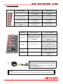
PARTS SUPPLIED
OPTIONAL FUNCTIONS
- AL2SW24 power supply unit
- Bracket and screws to fix power supply unit
- 2 x 47KOhm + 2 x 4K7 Ohm for NF1002 panel only
- 4 x 47KOhm + 6 x 4K7 Ohm for NF1004 and NF2000 panels
- Tecnical and programming manual
- User manual
- CD-Rom with documentation and configuration software
- Output for fire devices (GSM, Sounders)
- Outputs delay (DAY / NIGHT mode)
- Fault signal from points (NF2000 only)
- Correlation of alarm signals (Type A and B detection check)
- Unavailability of addressable points (Disablements devices, output modules, acoustic devices - NF2000 only)
- TEST condition (Test zones, outputs, loop outputs, loop
sounders, display, LED, buzzer)
3
090040787 - NF1002 - NF1004 - NF2000 - User Manual
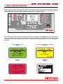
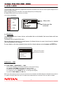
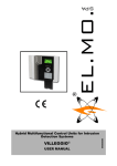
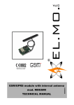
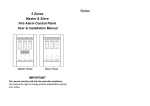
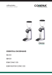
2. PANEL DISPLAYS AND KEYS
Below is the front label; all functions and states of the control panels are shown by and managed using the
graphic display and they are indicated by coloured LED indicators. The control keys of the many panel functions
make panel control and programming operations extremely easy and user-friendly.
One of the features of the new graphic display is the option of changing the backlighting colour according to the
status of the control unit. During normal operation, the display backlight will be GREEN, YELLOW in case of fault
or anomaly, RED in case of alarm events. When the control unit is being programmed or set, the backlight will
be WHITE.
Normal operation mode
GREEN
Alert for anomaly or wrong connection
YELLOW
Alarm alert
RED
Setup mode
WHITE
4
User Manual - NF1002 - NF1004 - NF2000 - 090040787
2.1 Panel LED indicators
LED name
Colour
Indication
POWER
GREEN
230V Power
SILENCE
YELLOW
Acoustic devices silenced
PRE-ALARM
RED
Alarm check + pre-alarm ON
INVEST. DELAY
YELLOW
Acknowledgment timer or
Investigation timer active
DAY / NIGHT
YELLOW
Day / Night mode
LED name
Colour
Fixed Light
Blinking
FIRE
RED
Alarm event(s) ON with silenced sounder
Alarm events ON
GSM ON
RED
Telephone dialler ON
Waiting a confirm
DISABLE
YELLOW
Disabled elements
-----
TEST
YELLOW
System element(s) is / are being tested
-----
GENERAL FAULT
YELLOW
Fault events ON with silenced buzzer
Fault events ON
SYSTEM FAULT
YELLOW
CPU fault with silenced buzzer
-----
SOUNDERS FAULT /
DISABLED
YELLOW
Sounders disabled
Sounders fault
GSM FAULT /
DISABLED
YELLOW
GSM disabled
GSM fault
5
090040787 - NF1002 - NF1004 - NF2000 - User Manual
2.2 Panel function keys
Level 1 Function
Level 2 Function
Level 3 Function
----
Enters the selected menu /
Confirms data
Enters the selected menu /
Confirms data
Scrolls events UP
Moves the selection upwards
Moves the selection upwards
Scrolls events DOWN
Moves the selection
downwards
Moves the selection
downwards
Displays fault events, if at the
same time alarm events are
present
Returns to previous menu /
Delete operation
Returns to previous menu /
Deletes operation
Key name
Level 1 Function
Level 2 / 3 Function
EVACUATE
During panel acknowledgment
or investigation time it resets
panel delay time intervals and
sets the panel to alarm
condition
During panel idle status, it
generates an "evacuate" event and
sets the panel to alarm condition.
During panel acknowledgment or
investigation time it operates as
seen at level 1.
At level 3 the key is disabled.
SILENCE
Silences the buzzer
During panel alarm or fault
condition. it silences acoustic
devices.
If pressed again, it re-activates such
devices. During Day/Night mode
acknowledgment time it sets the
panel to investigation mode
RESET
-----
During panel alarm or fault
condition, it resets the panel.
DAY / NIGHT
-----
It enables / disables day/night
mode. At level 3 the key is
disabled.
To access LEVEL 2:
insert the special key supplied with the fire panel into the level
selector and rotate it: you will switch from LEVEL 1 to LEVEL 2.
To access LEVEL 3:
once at level 2, scroll the menu and insert a PASSWORD for
the PROGRAMMING section.
WARNING
To restore the alarm viewing, you must access to the Level 2 by turning the key and pressing the ESC button.
6
User Manual - NF1002 - NF1004 - NF2000 - 090040787
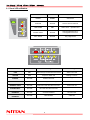
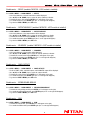
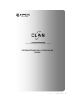
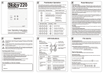
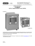
3. LEVEL 2 MENU
To access LEVEL 2 menu, insert the key supplied with the panel into the plastic lock on the front of the fire panel housing then turn it
and set it to LEVEL 2 position.
Display backlight will turn white and LEVEL 2 menu will be displayed as per following image.
Use ,, ENTER and ESC keys to browse Level 2 Menu.
Level 2 menu starting display:
= ENTER
Menu title
= UP
Submenu title
selected
= DOWN
= ESC
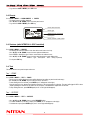
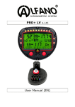
3.1 Disablings
This menu displays lists of zones, devices, and modules that can be disabled, their current status and items
already disabled.
The display below is typical of this menu.
When on the right of an item the "x" symbol appears, it indicates that one (or more) of such item(s) is disabled
(see Output Modules in the example.)
For more details on the item(s) disabled, please enter the relevant submenu using the arrows and ENTER key.
Disablings
ZONE
One (or more) output
module(s) is disabled
Device
Output Modules
X
Sounders.
Panel Outputs
Disablements - ZONE
Go to LEVEL 2 MENU > DISABLEMENTS > ZONE
- A list of zones will display (zones displayed depends on panel model and setup)
- Use (UP) and (DOWN) keys to select the zone(s) to disable.
- To disable the zone selected press ENTER (an ’X’ will appear on the right).
- To re-enable the zone, press ENTER again (the ’X’ on the right will disappear).
- To go back to LEVEL 2 MENU, press ESC twice.
NOTE: when all the addressed devices connected to the same zone are disabled, such ZONE will appear as disabled in the menu above
("x" symbol on the right.) When such zone is re-enabled, all the addressed devices connected to such zone will be re-enabled.
7
090040787 - NF1002 - NF1004 - NF2000 - User Manual
Disablements - DEVICE (enabled if NFEXP20 - LOOP module is installed)
Go to LEVEL 2 MENU > DISABLEMENTS > DEVICE
- A list of the addresses of the self-learnt devices will be displayed.
- Use (UP) and (DOWN) keys to select the device (address) to disable.
- To disable the device selected press ENTER (an ’X’ will appear on the right).
- To re-enable the device, press ENTER again (the ’X’ on the right will disappear).
- To go back to LEVEL 2 MENU, press ESC twice.
Disablements - OUTPUT MODULES (enabled if NFEXP20 - LOOP module is installed)
Go to LEVEL 2 MENU > DISABLEMENTS > OUTPUT MODULES
- A list of the addresses of the output modules will be displayed.
- Use (UP) and (DOWN) keys to select the module (address) to disable.
- To disable the module selected press ENTER (an ’X’ will appear on the right).
- To re-enable the module, press ENTER again (the ’X’ on the right will disappear).
- To go back to LEVEL 2 MENU, press ESC twice.
Disablements - SOUNDERS (enabled if NFEXP20 - LOOP module is installed)
Go to LEVEL 2 MENU > DISABLEMENTS > SOUNDERS
- A list of the addresses of the sounders will be displayed.
- Use (UP) and (DOWN) keys to select the sounder (address) to disable.
- To disable the sounder selected press ENTER (an ’X’ will appear on the right).
- To re-enable the sounder, press ENTER again (the ’X’ on the right will disappear).
- To go back to LEVEL 2 MENU, press ESC twice.
Disablements - PANEL OUTPUTS
Go to LEVEL 2 MENU > DISABLEMENTS > PANEL OUTPUTS
- The list of ZONES, AUX1 and AUX2 outputs, and SOUNDERS output will be displayed.
- Use (UP) and (DOWN) keys to select the output to disable.
- To disable the output selected press ENTER (an ’X’ will appear on the right).
- To re-enable the output, press ENTER again (the ’X’ on the right will disappear).
- To go back to LEVEL 2 MENU, press ESC twice.
Disablements - EXTINGUISHING MODULE
Go to LEVEL 2 MENU > DISABLEMENTS > EXTINGUISHING MODULE
- To disable the extinguishing module press ENTER (an ’X’ will appear on the right).
- To re-enable the extinguishing module, press ENTER again (the ’X’ on the right will disappear).
- To go back to LEVEL 2 MENU, press ESC twice.
Disablements - GSM
Go to LEVEL 2 MENU > DISABLEMENTS > GSM
- To disable the GSM module, press ENTER (an ’X’ will appear on the right).
- To re-enable the GSM module, press ENTER again (the ’X’ on the right will disappear).
8
User Manual - NF1002 - NF1004 - NF2000 - 090040787
- To go back to LEVEL 2 MENU, press ESC twice.
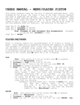
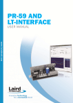
3.2 Events
Go to LEVEL 2 MENU > DISABLEMENTS > EVENTS
- The panel events log will be displayed.
- Use (UP) and (DOWN) keys to browse panel events.
- To go back to LEVEL 2 MENU, press ESC key.
Event date and time
Event type
Alarmed zone and device
Description
Event number / Total events
3.3 Devices (with NFEXP20 -LOOP installed)
Go to LEVEL 2 MENU > DEVICES
- The display will show the address of the first devices self-learn to the loop.
- Use (UP) and (DOWN) keys to browse registered addresses.
- Press ENTER to display the type of device connected to the address in use.
- Use (UP) and (DOWN) keys to browse memorized devices and display their:
Address - Type - Description - Zone - Group (if present)
- To exit press ESC key.
3.4 Test
This menu allows to test panel outputs and zones.
Test - ZONES
Go to LEVEL 2 MENU > TEST > ZONES
- The list of zones will be displayed (zones will be displayed according to panel model and setup.)
- Use (UP) and (DOWN) keys to select the zone to be tested.
- To start testing the zone selected, press ENTER (an ’X’ will appear on the right).
Now the zone has to be alarmed by triggering a detector or the zone emergency call point. The panel will trigger AL.REL. alarm
output signalling the detection of the sensor or the call point; it will disable the output after 10 seconds.
- To stop testing this zone, press ENTER again (the ’X’ on the right will disappear).
Test - OUTPUTS
Go to LEVEL 2 MENU > TEST > OUTPUTS
- Use (UP) and (DOWN) keys to select SOUNDER option.
- To enable SOUNDER (or AL.REL.) output, press ENTER (an ’X’ will appear on the right).
- To disable the output, press ENTER again (the ’X’ on the right will disappear).
9
090040787 - NF1002 - NF1004 - NF2000 - User Manual
- Use (UP) and (DOWN) keys to select ZONE 1 (valid for all zones connected).
- To enable ZONE 1 output, press ENTER (an ’X’ will appear on the right).
- To disable the output, press ENTER again (the ’X’ on the right will disappear).
[OUTPUTS are: relay outputs of optional NFREL24 board + digital outputs of panel I/O terminals, if setup]
- Use (UP) and (DOWN) keys to select FAULT option.
- To enable FAULT output, press ENTER (an ’X’ will appear on the right).
- To disable the output, press ENTER again (the ’X’ on the right will disappear).
- Use (UP) and (DOWN) keys to select AUX 1 option.
- To enable AUX 1 relay, press ENTER (an ’X’ will appear on the right).
- To disable the relay, press ENTER again (the ’X’ on the right will disappear).
- Use (UP) and (DOWN) keys to select AUX 2 option.
- To enable AUX 2 relay, press ENTER (an ’X’ will appear on the right).
- To disable the relay, press ENTER again (the ’X’ on the right will disappear).
Test - LOOP OUTPUTS (with NFEXP20 -LOOP installed)
Go to LEVEL 2 MENU > TEST > LOOP OUTPUTS
- The list of addresses of output modules self-learnt to the loop will be displayed.
- Use (UP) and (DOWN) keys to select the address of the output to be tested.
- To enable the selected output, press ENTER (an ’X’ will appear on the right).
- To disable the output, press ENTER again (the ’X’ on the right will disappear).
- To exit test mode and go back to TEST menu press ESC key.
Test - LOOP SOUNDER (with NFEXP20 -LOOP installed)
Go to LEVEL 2 MENU > TEST > LOOP SOUNDERS
- The list of addresses of SOUNDERS modules self-learnt to the loop will be displayed.
- Use (UP) and (DOWN) keys to select the address of the module to be tested.
- To enable the selected sounder, press ENTER (an ’X’ will appear on the right).
- To disable the sounder, press ENTER again (the ’X’ on the right will disappear).
- To exit test mode and go back to TEST menu press ESC key.
Test - DISPLAY
Go to LEVEL 2 MENU > TEST > DISPLAY
- A vertical bar will start displaying from the left side of the graphic display and will switch on all the pixels of the display.
- At the same time, the display backlight will change colour every second in sequencial mode.
- To exit test mode and go back to TEST menu press ESC key.
Test - LED
Go to LEVEL 2 MENU > TEST > LED
- The LEDs on the panel front cover will switch on for 2 seconds all at the same time.
- The panel will return to TEST menu after 2 seconds automatically.
Test - BUZZER
Go to LEVEL 2 MENU > TEST > BUZZER
- The panel buzzer will be enabled for 5 seconds.
- The panel will return to TEST menu after 5 seconds automatically.
10
User Manual - NF1002 - NF1004 - NF2000 - 090040787
4. CONTENTS
1. GENERALS . . . . . . . . . . . . . . . . . . . . . . . . . . . . . . . . . . . . . . . . . . . . . . . . . . . . . . . . . . . . . . . . . . . . . . . . . 3
2. PANEL DISPLAYS AND KEYS . . . . . . . . . . . . . . . . . . . . . . . . . . . . . . . . . . . . . . . . . . . . . . . . . . . . . . . . . . . 4
2.1.Panel LED indicators . . . . . . . . . . . . . . . . . . . . . . . . . . . . . . . . . . . . . . . . . . . . . . . . . . . . . . . . . . . . . . 5
2.2.Panel function keys . . . . . . . . . . . . . . . . . . . . . . . . . . . . . . . . . . . . . . . . . . . . . . . . . . . . . . . . . . . . . . . 6
3. LEVEL 2 MENU . . . . . . . . . . . . . . . . . . . . . . . . . . . . . . . . . . . . . . . . . . . . . . . . . . . . . . . . . . . . . . . . . . . . . . 7
3.1.Disablings . . . . . . . . . . . . . . . . . . . . . . . . . . . . . . . . . . . . . . . . . . . . . . . . . . . . . . . . . . . . . . . . . . . . . . . 7
3.2.Events . . . . . . . . . . . . . . . . . . . . . . . . . . . . . . . . . . . . . . . . . . . . . . . . . . . . . . . . . . . . . . . . . . . . . . . . . . 9
3.3.Devices (with NFEXP20 -LOOP installed) . . . . . . . . . . . . . . . . . . . . . . . . . . . . . . . . . . . . . . . . . . . . . . 9
3.4.Test . . . . . . . . . . . . . . . . . . . . . . . . . . . . . . . . . . . . . . . . . . . . . . . . . . . . . . . . . . . . . . . . . . . . . . . . . . . . 9
4. CONTENTS . . . . . . . . . . . . . . . . . . . . . . . . . . . . . . . . . . . . . . . . . . . . . . . . . . . . . . . . . . . . . . . . . . . . . . . . 11
11
Conventional / Addressable Microprocessor-Based Fire Panels NF1002 - NF1004 - NF2000 User Manual February 2014 Edition
090040787
Product specifications and details as described above do not bind the manufacturer and may ba altered without prior notice.
NITTAN COMPANY, LIMITED 1-54-5 Sasazuka, Shibuya-ku Tokyo 151-8535, Japan