1
Disassembly / Reassembly Procedures
4-6.
Rear Panel
Necessary tools: Phillips crosshead screwdriver (medium), open-ended spanner 8mm, knife.
Necessary materials: two tie-wraps (2.5 – 3 mm wide).
Approximate time: 10 minutes.
Note:
To remove the rear panel, it is necessary to perform the ‘Plastic Side Covers’ Procedure (see
Section 4-3) first.
Perform the following steps:
1.
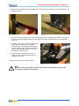
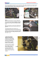
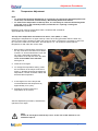
See figure 21.
Cut the two tie-wraps (arrows) at the left-hand side of the machine. Remove the blue cable
connector from the overtemperature switch (1). Remove the nut from the ground connection stud
(2).
1
2
fig. 21
fig. 22
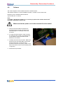
2.
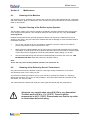
Remove the seven crosshead self-tapping screws from the rear panel (see figure 22).
3.
Carefully pull the rear panel backward, whilst pulling the two wires (the yellow/green and the blue
one) back through the plastic protective bushing, that’s mounted in the left-hand framesheet.
4.
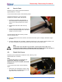
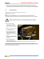
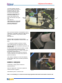
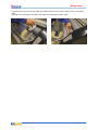
When the wires are clear from the bushing, swing the rear panel a quarter turn away from the
machine. Take care not to damage the wires (1) going to the motor. See figure 23.
5.
To mount the rear panel back to the machine
again, swing it far enough towards the
machine, to insert the two wires into the
bushing.
1
6.
Whilst pulling the wires through the bushing,
swing the rear panel further to the machine.
7.
When mounting the rear panel, make sure that
the two slots (2), on either side in the panel,
grab the two bent parts at the underside of the
framesheets.
8.
Next, push the rear panel upward to its original
position and use the crosshead screws to
fasten the panel again. Do not forget the
serrated washers!
7
4-7
2
fig. 23
February 2000