1
Disassembly / Reassembly Procedures
9.
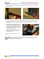
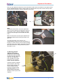
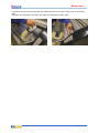
Apply the two new tie-wraps exactly on the original positions (into the holes), put the blue
connector back onto the overtemperature switch, and mount the ground wire back to it’s position.
Put the serrated washers back the way they came off: one on either side of the two wire-eyelets.
4-7.
Solid State Relay
Necessary tools: medium flat-head screwdriver, Allen key 3 mm.
Approximate time: 5 minutes.
Note:
To remove the Solid State Relay, it is necessary to perform the ‘Plastic Side Covers’
disassembly procedure (see Section 4-3) first. Only the right hand cover has to be removed.
Make sure that the power cord is disconnected from the mains!
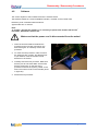
Perform the following steps:
1.
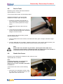
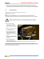
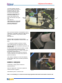
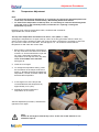
Loosen all four screws that
clamp the wires. They are
marked 1 through 4. See figure
24.
2.
Bend the wires a bit away from
the Solid State Relay.
3.
Remove the two M4 bolts that
hold the Solid State Relay
together with the bent sheet
(fire enclosure), that’s mounted
behind it.
4.
Now you can remove the Solid
State Relay, together with the
bent sheet.
5.
When mounting the Relay,
fig. 24
make sure that the four
clamping screws and the two
M4 bolts are tight. Don’t forget the serrated washers that belong under the M4 bolt heads.
Note: make sure, that the relay is mounted in the proper way: the coding on the blue wires
should correspond with the numbers on the relay; the two black wires on clamp no. 1, the wire
from the heating element on clamp no. 2.
8
4-8
February 2000