1
Foreword
Thank you for choosing Projoy PROPD Series Frequency Inverter. This product made
by Projoy is based on years of experience in professional production and sale, and
designed for solar pump inverter
This manual provides user the relevant precautions on installation, operational
parameter setting, abnormal diagnosis, routine maintenance and safe use. In order to
ensure correct installation and operation of the frequency converter, please carefully
read this manual before installing it.
For any problem when using this product, please contact your local dealer authorized by
this company or directly contact this company, our professionals are happy to serve you.
The end-users should hold this manual, and keep it well for future maintenance & care,
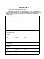
and other application occasions. For any problem within the warranty period, please fill
out the warranty card and fax it to the our authorized dealer.
The contents of this manual are subject to change without prior notice. To obtain the
latest information, please visit our website.
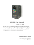
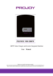
For more product information ,please visit:http://www.projoy-solar.com
Projoy
March, 2015
Table of contents
Foreword........................................................................................................................1
Table of contents............................................................................................................2
Chapter 1.Inspection and safety precautions................................................................. 1
1-1. Inspection after unpacking..................................................................................... 1
1-1-1Instructions on nameplate..................................................................................... 1
1-1-2Safety precautions.................................................................................................1
1-2. Safety precautions.................................................................................................. 1
1-3. Precautions............................................................................................................. 4
1-4. Scope of applications............................................................................................. 6
Chapter 2 Standard specifications................................................................................. 8
2-1. Technical specifications......................................................................................... 8
2-2. Standard specifications...........................................................................................8
2-3. Dimensions...........................................................................................................12
2-3-1. Appearance and installation holes size............................................................. 12
2-3-2. Projoy series......................................................................................................13
2-3-3. Keyboard size diagram..................................................................................... 14
Chapter 3 Keyboard.....................................................................................................16
3-1. Keyboard description........................................................................................... 16
3-2. Keyboard Indicators............................................................................................. 16
3-3. Description of operation panel keys.....................................................................17
3-4. Examples of parameter settings........................................................................... 17
3-4-1. Instructions on viewing and modifying function code..................................... 17
3-4-2. The way to read parameters in various status................................................... 19
3-4-3. Password settings..............................................................................................19
3-4-4. Motor parameter auto tunning.......................................................................... 19
Chapter 4 Commissioning........................................................................................... 21
Chapter 5 Function parameter..................................................................................... 22
5-1. Menu grouping..................................................................................................... 22
5-1-1. d0Group - Monitoring function group.............................................................. 23
5-1-2. F0 Group -Basic function group....................................................................... 25
5-1-3. F1 Input terminals group...................................................................................27
5-1-4. F2 Group - Output terminals group.................................................................. 32
5-1-5. F3 Group - Start and stop control group........................................................... 36
5-1-6. F4 V/Fcontrol group......................................................................................... 37
5-1-7. F6 Keybaord and Display................................................................................. 38
5-1-8. F7 Group - Auxiliary function group................................................................40
5-1-9. F8 Group - Fault and protection....................................................................... 40
5-1-10. F9 Group - Communication parameter...........................................................42
5-1-11. FB Group - Control optimization parameters................................................. 44
5-1-12. E0 Solar water pump special group................................................................ 44
5-1-13. E2 PID Function Group.................................................................................. 46
5-1-14. E3 Virtual terminal group............................................................................... 49
5-1-15. b0 Motor parameters group.............................................................................52
5-1-16. y0 Function code management group.............................................................54
5-1-17. y1 Fault query group.......................................................................................56
Chapter 6 EMC (Electromagnetic Compatibility).......................................................61
6-1. Definition............................................................................................................. 61
6-2. EMC standard.......................................................................................................61
6-3. EMC directive...................................................................................................... 61
6-3-1. Harmonic effect................................................................................................ 61
6-3-2. Electromagnetic interference and installation precautions............................... 61
6-3-3. Remedies for the interferences from the surrounding electromagnetic
equipments to the inverter........................................................................................... 62
6-3-4. Remedies for the interferences from the inverter to the surrounding
electromagnetic equipments........................................................................................ 62
6-3-5. Remedies for leakage current........................................................................... 62
6-3-6. Precautions on installing EMC input filter at the input end of power supply.. 63
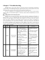
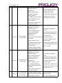
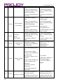
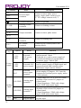
Chapter 7 Troubleshooting.......................................................................................... 64
7-1. Fault alarm and countermeasures.........................................................................64
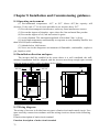
Chapter 8 Installation and Commissioning guidance..................................................71
8-1. Operating environment.........................................................................................71
8-2. Installation direction and space............................................................................71
8-3. Wiring diagram.....................................................................................................71
Chapter 9 Maintenance and Repair............................................................................. 81
9-1. Inspection and Maintenance.................................................................................81
9-2. Parts for regular replacement............................................................................... 82
9-3. Storage..................................................................................................................82
9-4. Capacitor.............................................................................................................. 82
9-4-1. Capacitor rebuilt............................................................................................... 82
9-5. Measuring and readings....................................................................................... 83
Chapter 10 Warranty....................................................................................................84
Warranty Card............................................................................................................. 85
Chapter 1.Inspection and safety precautions
Projoy frequency inverters have been tested and inspected before leaving factory.
After purchasing, please check if its package is damaged due to careless transportation,
and if the specifications and model of the product are consistent with your order
requirements. For any problem, please contact your local authorized Projoy dealer or
directly contact this company.
1-1.Inspection after unpacking
Check if that packing container contains this unit, one manual and one warranty
card.
※ Check the nameplate on the side of the frequency inverter to ensure that the
product you have received is right the one you ordered.
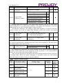
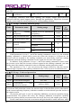
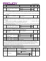
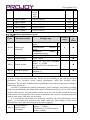
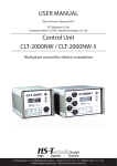
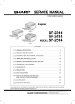
1-1-1 .Instructions on nameplate
※
Inverter model
MODEL
PROPD-4T7500
Output Power Spec.
POWER
7.5kW
INPUT
DC 1PH 350 750V AC 3PH 380V
Input Source Spec.
Output Spec.
OUTPUT AC 3PH 0 380V 17A 0 400Hz
Bar code
Production Sequence Number
ZPB1A0100001
1-1-2 Safety precautions
Rated Output Power
Example:7500:7.5kW,400:0.4kW
Input Voltage Level:
2ST:DC200-380v , single / three phase AC 220V
4T:DC350-750v , three phase AC 380V
PD:Pumping Driver
Power Inverter
1-2.Safety precautions
Safety precautions in this manual are divided into the following two categories:
Danger: the dangers caused by failure to perform required operation, may result in
serious injury or even death;
1
User manual V1.0
Caution:the dangers caused by failure to perform required operation, may result in
moderate injury or minor injury, and equipment damage;
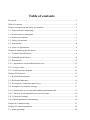
Process
Type
Explanation
● When unpacking, if control system with water,
parts missed
or component damaged are found,
do not install!
● If packing list does not match the real name, do
not install!
● Gently carry with care, otherwise there is the risk
Before
of damage to equipment!
Danger
installation
● Please do not use the damaged driver or the
frequency inverter with missed pieces, otherwise
there is the risk of injury!
● Do not use your hand to touch the control system
components, otherwise there is the risk of
electrostatic damage!
● Please install the unit on the metal or flame
retardant objects; away from combustible material.
Failure to do so may cause a fire!
Danger
● Never twist the mounting bolts of the equipment
components, especially the bolt with the red mark!
● Do not let the lead wires or screws fall into the
When
driver. Otherwise which may cause damage to the
installing
driver!
● Keep the driver installed in the place where less
Note
vibration, avoid direct sunlight.
● When two or more converters are installed in a
cabinet, please pay attention to the installation
location, ensure the good heat dissipation effect.
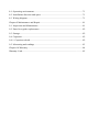
● Must comply with this manual's guidance, any
construction shall be performed by a professional
electrician, otherwise there would be the
unexpected risk !
● A circuit breaker must be set between the inverter
and the power supply to separate them, otherwise it
may cause a fire!
● Verify if power is a zero-energy status before
wiring, otherwise there is a risk of electric shock!
When wiring
● The inverter shall be grounded correctly
Danger
according to standard specifications, otherwise
there is a danger of electrical shock!
● Ensure that the distribution line meets the
regional safety standards of EMC requirements.
The diameter of used wire shall refer to the
recommendations of this manual. Otherwise it may
cause an accident!
● Never directly connect braking resistor to the DC
bus P(+) and P(-) terminals. Otherwise it may cause
2
User manual V1.0
Note
Before
energizing
Danger
After
energizing
Danger
During
operation
Danger
a fire!
● Encoder must use the shielded wire, and the
shielding layer must ensure the single-ended
grounded!
● Please confirm whether the input power voltage
is same as the inverter rated voltage; wiring
positions of power input terminals(R, S, T) and
output terminals(U, V, W) are correct or not; and
note that if there is a short circuit in the peripheral
circuit connected to driver, if the connected lines
are tight, otherwise it may cause damage to the
driver!
● Do not need to perform withstand voltage test for
any part of the inverter, this product has been tested
before leaving factory. Otherwise it may cause an
accident!
● The inverter's cover plate must be closed before
power on. Otherwise it may cause an electric shock!
● Wiring of all external accessories must comply
with the guidance of this manual, please correctly
wiring in accordance with the circuit connection
methods described in this manual. Otherwise it may
cause an accident!
● Do not open cover plate after energizing.
Otherwise there is a risk of electric shock!
● Do not touch the driver and peripheral circuits
with wet hands. Otherwise there is a risk of electric
shock!
● Do not touch any input and output terminals of
the inverter. Otherwise there is a risk of electric
shock!
● The inverter automatically perform the safety
testing for the external strong electrical circuit in
the early stages of energizing, therefore never touch
the driver terminals(U, V, W) or motor terminals,
otherwise there is a risk of electric shock!
● If you need to identify the parameters, please pay
attention to the danger of injury during motor
rotation. Otherwise it may cause an accident!
● Please do not change the inverter manufacturer
parameters. Otherwise it may cause damage to this
unit!
● Do not touch the cooling fan and the discharge
resistor to feel the temperature. Otherwise it may
cause burns!
● Non-professional personnel is not allowed to
detect signal when operating. Doing so may cause
personal injury or damage to this unit!
3
User manual V1.0
Note
When
maintaining
Danger
● When the inverter is operating, you should avoid
that objects fall into this unit.Otherwise cause
damage to this unit!
● Do not start/stop the driver by switching on/off
contactor. Otherwise cause damage to this unit!
● Do not perform repairs and maintenance for the
live electrical equipment. Otherwise there is a risk
of electric shock!
● The repairs and maintenance task can be
performed only when the inverter bus voltage is
lower than 36V,Otherwise, the residual charge from
capacitor would cause personal injury!
● Non-well-trained professional personnel is not
allowed to perform repairs and maintenance of
inverter. Doing this may cause personal injury or
damage to this unit!
● After replacing the inverter, parameter settings
must be redone, all pluggable plugs can be operated
only in the case of powering off!
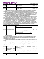
1-3.Precautions
N
o.
1
2
3
4
5
6
4
Type
Explanation
Please perform motor insulation inspection for the first time
use, re-use after leaving unused for a long time as well as
regular check, in order to prevent damage to the inverter
Motor insulation
because of the motor's winding insulation failure. Wiring
inspection
between motor and inverter shall be disconnected, it is
recommended that the 500V voltage type megger should be
adopted and insulation resistance shall be not less than 5MΩ.
If the rated capacity of the selected motor does not match the
inverter, especially when the inverter rated power is greater
Motor thermal
than the motor rated power, be sure to adjust the motor
protection
protection parameter values inside inverter or install thermal
relay in the front of motor for motor protection.
The inverter output frequency rang is 0Hz to
Run over
3200Hz(Maz.vector control only supports 300Hz). If the user
power
is required to run at 50Hz or more, please consider the
frequency
endurance of your mechanical devices.
Vibrations of
Inverter output frequency may be encountered mechanical
mechanical
resonance point of the load device, you can set jump
device
frequency parameter inside inverter to avoid the case.
The inverter output voltage is PWM wave that contains a
Motor heat
certain amount of harmonics, so the temperature rise, noise
and noise
and vibration of motor show a slight higher than frequency
power frequency operation.
Output side
The inverter output is PWM wave, if the piezo-resistor for
with piezolightning protection or the capacitor for improving power
User manual V1.0
resistor or
capacitor for
improving
power factor
factor is installed in the output side, which easily cause the
inverter instantaneous over-current or even cause damage to
the inverter. Please do not use.
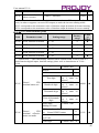
If contactor is installed between power supply and inverter,
the contactor is not allowed to start/stop the inverter.
Necessarily need to use the contactor to control the inverter
start/stop, the interval should not be less than one hour.
Frequent charging and discharging may reduce the service
life of the inverter capacitor. If the contactor or switch is
equipped between output terminals and motor, the inverter
should be turned on/off without output status, otherwise
which easily lead to damage to the inverter module.
PI series inverter is not suitable for use beyond the allowable
operating voltage described in this manual, which easily
cause damage to the parts inside inverter. If necessary, please
use the corresponding transformer to change voltage.
7
Contactor or
switch used in
the inverter
input/output
terminals
8
Use
other
than the rated
voltage
9
Never change
3-phase input
to 2-phase
input
10
Lightning
surge
protection
11
High altitude
and derating
application
12
Special use
13
Precautions
for scrap
disposal of
the inverter
When electrolytic capacitors on the main circuit and printed
circuit board as well as plastic parts are burned, it may
produce toxic gases.Please disposing as industrial waste.
Adaptive
motor
1) Standard adaptive motor shall be four-pole asynchronous
squirrel-cage induction motor or permanent magnet
synchronous motor. Apart from the said motors, please select
the inverter according to the motor rated current.
2) The cooling fan and the rotor shaft for non-inverter motor
are coaxially connected, the fan cooling effect is reduced
when the rotational speed is reduced, therefore, when the
motor works in overheating occasions, a strong exhaust fan
should be retrofitted or replace non-inverter motor with the
inverter motor.
3) The inverter has built-in the adaptive motor standard
14
Never change PROPD series 3-phase inverter to 2-phase one
for application. Otherwise it will lead to malfunction or
damage to the inverter.
The series inverter is equipped with lightning over-current
protection device, so it has the ability of self-protection to
lightning induction. For the area where lightning is frequent,
user should also install the extra protection in the front of the
inverter.
When the inverter is used in areas over 1000m altitude, it is
required to reduce frequency because the thin air will
decrease the cooling effect of inverter. Please consult our
technician for details on the application.
If the user need to use methods other than the suggested
wiring diagram provided in this manual, such as common DC
bus, please consult our technician.
5
User manual V1.0
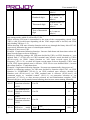
15
Others
parameters, according to the actual situation, please identify
motor parameters or accordingly modify the default values to
try to meet the actual value, otherwise it will operation affect
and protection performance;
4) When short-circuit of cable or motor internal will activate
the inverter alarm, even bombing. Therefore, firstly perform
insulation short-circuit test for the initial installation of the
motor and cable, routine maintenance often also need to
perform such test. Note that the parts to be tested and the
inverter shall be disconnected completely when testing.
1) Never connect the AC power to the inverter output
terminals(U, V, W).
2) Properly fix and lock the panel before powering on, so as
to avoid hurting the personal safety due to internal poor
capacitors.
3) Never perform wiring, checking and other operations after
power is turned on.
4) Do not touch the internal circuit board and its components
in order to avoid the risk of electric shock after this unit is
powered,
5) Do not touch internal circuit board and any parts after
powering off and within five minutes after keyboard
indicator lamp goes out, you must use the instrument to
confirm that internal capacitor has been discharged fully,
otherwise there is a danger of electric shock.
6) Body static electricity will seriously damage the internal
MOS field-effect transistors, etc., if there are not anti-static
measures, do not touch the printed circuit board and IGBT
internal device with hand, otherwise it may cause a
malfunction.
7)The ground terminal of the inverter(E or
) shall be
earthed firmly according to the provisions of the National
Electrical Safety and other relevant standards. Do not shut
down(power off) by pulling switch, and only cut off the
power until the motor stopping operation.
8) It is required to add the optional input filter attachment so
as to meet CE standards
1-4.Scope of applications
※
※
※
6
This inverter is suitable for three-phase AC asynchronous motor and permanent
magnet synchronous motor.
This inverter can only be used in those occasions recognized by this company, an
unapproved use may result in fire, electric shock, explosion and other accidents.
If the inverter is used in such equipments(e.g: equipments for lifting persons,
aviation systems, safety equipment, etc.) and its malfunction may result in
personal injury or even death. In this case, please consult the manufacturer for
your application.
User manual V1.0
Only the well-trained personnel can be allowed to operate this unit, please
carefully read the instre1tions on safety, installation, operation and
maintenance before use. The safe operation of this unit depends on proper
transport, installation, operation and maintenance!
7
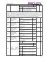
Chapter 2 Standard specifications
2-1.Technical specifications
Inverter
model
Input voltage
PROPD-2ST400
PROPD-2ST750
PROPD-2ST1500
1-phase or 3-phase
AC 220V
±10%;
Rated
output
power(kW)
Rated
output
current(A)
Adaptive
motor
0.4
2.5
0.4
0.75
4
0.75
1.5
7
1.5
PROPD-2ST2200
recommend
2.2
10
2.2
PROPD-2ST4000
DC 200V~450V
4.0
16
4.0
PROPD-2ST5500
5.5
25
5.5
PROPD-4T750
0.75
2.5
0.75
1.5
3.8
1.5
2.2
5.1
2.2
±10%;
4.0
9
4.0
PROPD-4T5500
recommend
5.5
13
5.5
PROPD-4T7500
DC 350V~750V
PROPD-4T1500
PROPD-4T2200
PROPD-4T4000
3-phase
AC380V
7.5
17
7.5
PROPD-4T11K
11
25
11
PROPD-4T15K
15
32
15
※Remarks:The power of solar modules should be up to 1.2 times higher than inverter
power
2-2.Standard specifications
Control system
Power
Items
8
Specifications
Voltage
and
frequency levels
Single-phase 220V±10%,50/60Hz±5%
Three-phase 220V±10%,50/60Hz±5%
Three-phase 380V±10%,50/60Hz±5%
Recommend pv
input
DC
voltage range
2ST:DC 200~450V;
4T:DC 350~750V
Control system
High performance vector control inverter based on DSP
Control method
V/F control, vector control W/O PG
Automatic
torque Realize low frequency (1Hz) and large output torque
boost function
control under the V/F control mode.
Acceleration/de
Straight or S-curve mode. Four times available and time
celeration
range is 0.0 to 6500.0s.
User manual V1.0
Items
Specifications
control
V/F curve mode
Over
load
capability
Maximum
frequency
Carrier
Frequency
Input
frequency
resolution
G type:rated current 150% - 1 minute, rated current 180% 2 seconds
Vector control:0 to 300Hz
V/F control:0 to 3200Hz
0.5 to 16kHz; automatically adjust carrier frequency
according to the load characteristics.
Digital setting: 0.01Hz Analog setting: maximum
frequency×0.1%
Start torque
G type: 0.5Hz/150% (vector control W/O PG)
Speed range
1:100 (vector control W/O PG)
Steady-speed
precision
Vector control W/O PG: ≤ ± 0.5% (rated synchronous
speed)
Torque response
≤ 40ms (vector control W/O PG)
Automatic torque boost; manual torque boost(0.1% to
30.0%)
DC braking frequency: 0.0Hz to max. frequency, braking
time:
0.0 to 100.0 seconds, braking current value: 0.0% to
100.0%
Jog Frequency Range: 0.00Hz to max. frequency;
Jog Ac/deceleration time: 0.0s to 6500.0s
Achieve up to 16-speed operation through the control
terminal
Easy to realize closed-loop control system for the process
control.
Torque boost
DC braking
Jogging control
Multi-speed
operation
Built-in PID
Peronalization
function
Linear, square root/m-th power, custom V/F curve
Automatic
voltage
regulation(AVR)
Automatically maintain a constant output voltage when the
voltage of electricity grid changes
The specific
function of solar
pump inveter
the biggest Optical power tracking,Light weak auto
sleep,Light intensity automatically wake up,High water
level automatic stop,Low water level automatic run,under
load protection.
Self-inspection
After powering on, peripheral equipment will perform
of peripherals
safety testing, such as ground, short circuit, etc.
after power-on
Common DC bus
Multiple inverters can use a common DC bus.
function
The current limiting algorithm is used to reduce the inverter
Quick current
overcurrent probability, and improve whole unit antilimiting
interference capability.
9
User manual V1.0
Items
Input signal
Timing control
Keyboard/terminal/communication
Frequency
setting
10 frequency settings available, including adjustable DC(0
to 10V), adjustable DC(0 to 20mA), panel potentiometer,
etc.
Start
signal
Multispeed
Emergenc
y stop
Rotate forward/reverse
At most 16-speed can be set(run by using the multi-function
terminals or program)
Interrupt controller output
When the protection function is active, you can automatically
or manually reset the fault condition.
PID feedback
Including DC(0 to 10V), DC(0 to 20mA)
signal
Running
Motor status display, stop, ac/deceleration, constant speed,
status
program running status.
Fault
Contact capacity :normally closed contact 5A/AC 250V,
output
normally open contact 3A/AC 250V,1A/DC 30V.
Two-way analog output, 16 signals can be selected such as
Analog
frequency, current, voltage and other, output signal range (0
output
to 10V / 0 to 20mA).
Output
At most 3-way output, there are 40 signals each way
signal
Limit frequency, jump frequency, frequency compensation,
Run function
auto-tuning, PID control
DC current
Built-in PID regulates braking current to ensure sufficient
braking
braking torque under no overcurrent condition.
Running
Three channels: operation panel, control terminals and
serial communication port. They can be switched through a
command
variety of ways.
channel
Total 5 frequency sources: digital, analog voltage, analog
Frequency
current, multi-speed and serial port. They can be switched
source
through a variety of ways.
6 digital input terminals, compatible with active PNP or
NPN input mode, one of them can be for high-speed pulse
Input terminals
input(0 to 100 kHz square wave); 2 analog input terminals
for voltage or current input.
Output signal
Running
Timing control function: time setting range(0m to 6500m)
Running
method
Fault reset
10
Specifications
User manual V1.0
Items
Output terminals
Display
Protection function
Inverter
protection
Specifications
2 digital output terminals, one of them can be for high-speed
pulse output(0 to 100kHz square wave); one relay output
terminal; 2 analog output terminals respectively for optional
range (0 to 20mA or 0 to 10V), they can be used to set
frequency, output frequency, speed and other physical
parameters.
Overvoltage
protection,
undervoltage
protection,
overcurrent protection, overload protection, overheat
protection, overcurrent stall protection, overvoltage stall
protection,
losting-phase
protection
(optional),
communication error, PID feedback signal abnormalities,
PG failure and short circuit to ground protection.
IGBT
temperature
Displays current temperature IGBT
display
Inverter
fan
Can be set
control
Instantaneous
Less than 15 milliseconds: continuous operation.
power-down
More than 15 milliseconds: automatic detection of motor
restart
speed, instantaneous power-down restart.
Speed start tracking
The inverter automatically tracks motor speed after it starts
method
Parameter
Protect inverter parameters by setting administrator
protection
Password and decoding
function
Runni Monitoring objects including: running frequency, set
frequency, bus voltage, output voltage, output current,
ng
output power, output torque, input terminal status, output
LED/OL infor
terminal status, analog AI1 value, analog AI2 value, motor
matio
ED
Actual running speed , PID set value percentage, PID
n
display
feedback value percentage.
keyboard Error At most save three error message, and the time, type,
messa voltage, current, frequency and work status can be queried
ge
when the failure is occurred.
LED display
Display parameters
OLED display
Copy parameter
Key lock and
function
selection
Optional, prompts operation content in Chinese/English
text.
Can upload and download function code information of
frequency converter, rapid replication parameters.
Lock part or all of keys, define the function scope of some
keys to prevent misuse.
11
User manual V1.0
Product standard
Environment
Commu
nication
Items
RS485
Specifications
The optional completely isolated RS485 communication
module can communicate with the host computer.
Environment
temperature
Storage
temperature
Environment
humidity
-10 ℃ to 40 ℃ (temperature at 40 ℃ to 50 ℃, please
derating for use)
Vibration
Altitude
Below 5.9m/s² (= 0.6g)
Indoor where no sunlight or corrosive, explosive gas and
water vapor, dust, flammable gas, oil mist, water vapor,
drip or salt, etc.
Below 1000m
Pollution degree
2
Product adopts
safety standards.
IEC61800-5-1:2007
Application sites
-20 ℃ to 65 ℃
Less than 90% R.H, no condensation.
Product
adopts
IEC61800-3:2005
EMC standards.
Cooling method
Forced air cooling and natural air cooling
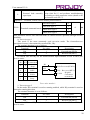
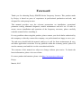
2-3.Dimensions
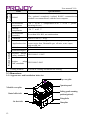
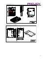
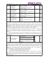
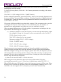
2-3-1.Appearance and installation holes size
Top cover plate
Movable cover plate
Control cable inlet
Air duct inlet
12
Operation panel
Sealing guard mounting
position(optional)
Fixing holes
Nameplate
User manual V1.0
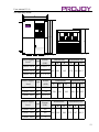
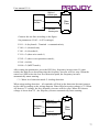
2-3-2.Projoy series
W
b
H
a
L
d
WARNING
Refer to the operation manual when adjust or inspect.
High voltage inside.Maintenance by the well-trained
personnel.
Confirm the output or control Confirm the output or
control wires are not grounded.
Perform parts replacement after discharge.
d
Power supply
Type
level
Power
(kW)
Dimensions
L
W
1-phase 220V G
0.4 to 1.5
3-phase 220V G
0.4 to 1.5 185 120
3-phase 380V G
0.75 to 2.2
Power supply
Type
level
Power
(kW)
1-phase 220V
G
2.2
3-phase 220V
G
2.2
3-phase 380V
G
4.0 to 5.5
Power supply
Type
level
Power
(kW)
1-phase 220V
G
4.0
3-phase 220V
G
4.0
3-phase 380V
G
7.5
Installation size
H
a
165
Dimensions
L
W
H
220
150
182
Dimensions
L
W
285 180
H
200
b
d
174 108 Ø5.3
Installation size
a
b
d
209 138 Ø5.3
Installation size
a
b
d
272 167 Ø5.5
13
User manual V1.0
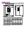
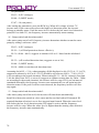
d
H
a
L
W
b
WARNING
Read instruction manual carefully before installation
and operation
High voltage inslde. Maintenance shorld be performed
by well-trained personel
Make sure to connect the ground terminal before
connecting orther terminals
Perform maintenance or inspection after the charge
LED turns off(fully discharged)
Power supply
Type
level
Dimensions
L
1-phase 220V
G
3-phase 220V
G
5.5~7.5 360
3-phase 380V
G
11~15
3-phase 220V
G
11
3-phase 220V
G
15
2-3-3.Keyboard size diagram
14
Power
(kW)
W
H
Installation size
a
b
d
5.5
220
225 340 150
Ø10
435
275
258 415 165
Ø10
480
296 262
460 200
Ø10
User manual V1.0
Keyboard case size diagram:
Install keyboard case on the panel, opening square hole is
required:(76±0.1)*(123±0.1)
15
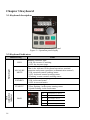
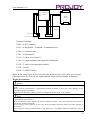
Chapter 3 Keyboard
3-1.Keyboard description
JPR6E9100 keyboard control panel
Figure 3-1 Operation panel display
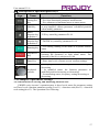
3-2.Keyboard Indicators
Indicator flag
Status Light
RUN
LOCAL/RE
MOTE
FWD/REV
Units
combination
indicator
TUNE/TC
16
HzAV
Name
Running indicator light
* ON: the inverter is working
* OFF: the inverter stops
Command indicator light
That is the indicator for keyboard operation, terminal
operation and remote operation (communication control)
* ON: terminal control working status
* OFF: keyboard control working status
* Flashing: remote control working status
Forward/reverse running light
* ON: in forward status
* OFF: in reversal status
Motor self-learning fault indicator
* Slow flashing: in the motor tunning status
* Quick flashing: in the fault status
Hz
A
V
RPM
%
frequency unit
current unit
voltage unit
speed unit
percentage
User manual V1.0
3-3.Description of operation panel keys
Sign
Name
Parameter
Setting/Esc
Key
Shift Key
Multifunction key
definition 1
Multifunction key
definition 2
Function
* Enter into the modified status of main menu
* Esc from functional parameter modification
* Esc submenu or functional menu to status menu
*Choose displayed parameter circularly under running
or stop interface; choose parameter’s modified position
when modify parameter
*UP key setted by parameter F6.18
* DOWN key setted by parameter F6.19
Running key
* For starting running in the mode of keyboard control
status
Stop/Reset
Key
* For stopping running in the running status; for
resetting the operation in fault alarm status. The
function of the key is subject to F6.00
Enter Key
* Enter into levels of menu screen, confirm settings.
Keyboard
encoder
* In query status, function parameter increasing or
decreasing
* In modified status, the function parameter or
modified position increasing or decreasing.
* In monitoring status, frequency setting increasing or
decreasing
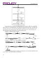
3-4.Examples of parameter settings
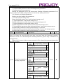
3-4-1.Instructions on viewing and modifying function code
PROPD series inverter’s operation pane is three levels menu for parameter setting
etc.Three levels: function parameter group (Level 1)→function code(level 2)→function
code setting(level 3). The operation is as following:
17
User manual V1.0
Power-on
Shutdown parameter display
PRG
PRG
Change
parameter group
First-level menu display
ENTER
Change function
parameter
selection
PRG
Second-level menu display
Change function
ENTER parameter
value
ENTER
PRG
Third-level menu display
Figure 3-2 Display status and operation processes
Description: Back to the level 2 menu from level 3 menu by PRG key or ENTER
key in the level 3 operation status. The differences between the two keys : ENTER will
be back to the level 2 menu and save parameter setting before back, and transfer to the
next function code automatically; PRG will be back to the level 2 menu directly, not
save parameter setting, then back to current function code.
Example 1 :Restore factory settings
Press
ENTER
Press
PRG
Press
ENTER
Press PRG
Press
PRG
Press
ENTER
to
confirm
Flicker
Example 2 :Change F0.01 from 50.00Hz to 40.00Hz
Press
PRG
Press
ENTER
Press
ENTER
Press
PRG
Press PRG
Press
ENTER
to
confirm
Flicker
Without twinkling parameter position, the function code can not be modified in the
level 3 menu. The reason maybe as following:
18
User manual V1.0
1) The function code can not be modified itself, eg: actual detecting parameters,
running record parameters.
2) The function code can not be modified in the running status. It must be
modified in the stop status.
3-4-2.The way to read parameters in various status
In stop or run status, operate shift key
to display a variety of status parameters
respectively. Parameter display selection depends on function code F6.01 (run
parameter 1), F6.02 (run parameter 2) and F6.03 (stop parameter 3).
In stop status, there are total 16 stop status parameters that can be set to display/not
display: set frequency, bus voltage, DI input status, DO output status, analog input AI1
voltage, analog input AI2 voltage, panel potentiometer input voltage, Actual count
value, Actual length value, PLC running step number, Actual speed display, PID
settings, high-speed pulse input frequency and reserve, switch and display the selected
parameter by pressing key orderly.
In running status,there are 5 running-status parameters:running frequency,setting
frequency,bus voltage,output voltage, output current default display, and other display
parameters: output power, output torque, DI input status, DO output status, analog
input AI1 voltage, analog input AI2 voltage, panel potentiometer input voltage, Actual
count value, Actual length value, linear speed, PID settings and PID feedback, etc,
their display depends on function code F6.01 and F6.02 switch and display the selected
parameter by pressing key orderly.
Inverter powers off and then powers on again, the displayed parameters are the
selected parameters before power-off.
SHIFT
3-4-3.Password settings
The inverter has password protection. When y0.01 become not zero, it is the
password and will be work after exit from function code modified status. Press PRG
key again, will display”----”. One must input the correct password to go to regular
menu, otherwise, inaccessible.
To cancel the password protection function, firstly enter correct password to access
and then set y0.01 to 0.
3-4-4.Motor parameter auto tunning
Choose vector control, one must input the motor’s parameters in the nameplate
accurately before running the inverter. PROPD series frequency inverter will match the
motor’s standard parameters according to its nameplate. The vector control is highly
depend on motor’s parameters. The parameters of the controlled motor must be
inputted accurately for the good control performance.
Motor parameter auto tunning steps are as follows:
Firstly select command source (F0.11=0) as the comment channel for operation
panel, then input the following parameters according to the actual motor parameters
(selection is based on the current motor):
Motor
Parameters
Selection
b0.00: motor type selection b0.01: motor rated
Motor
power
19
User manual V1.0
b0.02: motor rated voltage b0.03: motor rated
current
b0.04: motor rated frequency b0.05: motor rated
speed
For asynchronous motors
If the motor can NOT completely disengage its load, please select 1 (asynchronous
motor parameter static auto tunning) for b0.27, and then press the RUN key on the
keyboard panel.
If the motor can completely disengage its load, please select 2 (asynchronous
motor parameter comprehensive auto tunning) for b0.27, and then press the RUN key
on the keyboard panel, the inverter will automatically calculate the motor’s following
parameters:
Motor
Parameters
Selection
b0.06:asynchronous motor stator resistance
b0.07:asynchronous motor rotor resistance
Motor
b0.08:asynchronous motor leakage inductance
b0.09: asynchronous motor mutual inductance
b0.10: asynchronous motor no-load current
Complete motor parameter auto tunning
20
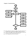
Chapter 4 Commissioning
Commissioning
Select control manner
(Set F0.00)
Correctly motor parameters
(Set b0.00
b0 . 05)
0:Vector control W/O PG
F0.00=?
2:V/F control
Select appropriate ac/deceleration time
(Set F0.13、F0.14)
Select command source
(Set F0.11)
Motor parameter self-learning
Select suitable frequency source
(Set F0.03)
Select motor start-up mode
(Set b0.27)
(Set F3.00)
Select appropriate ac/deceleration time
(Set F0.13、F0.14)
Select motor stop mode
(Set F3.07)
NO
Achieve the required control effect?
Start motor to run,observe the
phenomenon,if abnormal,please
refer to the troubleshooting
YES
Commissioning
Firstly confirm that AC input power supply voltage shall be within inverter
rated input voltage range before connecting power supply to the inverter.
Connect AC power supply to the R, S and T input terminals of the inverter,
or solar power to the R, T input terminals of the inverter.
Select the appropriate operation control method.
21
Chapter 5 Function parameter
5-1.Menu grouping
Note:
“★”: In running status, can not modify the parameter setting
“●”: The actual testing data, can not be modified
“☆”: In stop and run statuses, both can be changed;
“▲”: “Factory parameter”, no change about it.
“_” means the factory parameter is related to power or model. Please check the details in the
involved parameter introduction.
Change limit refers to whether the parameters are adjustable.
y0.01 is used for parameters protection password. Parameter menu can be enter into only after
inputting the right password in the function parameter mode or user change parameter mode. When the
y0.01 set to 0, the password is canceled.
F group is the basic function parameters,E group is to enhance function parameters, b group is a
function of motor parameters,d group is the monitoring function parameters.
PROPD series inverter , some parameters for the "factory reservations ", the serial number is not
listed in the function parameter list , resulting in some of the parameters in the table number is not
connected . Please do not attempt to modify the parameters which is not introduced in the manual , to
avoid errors.
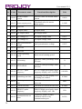
22
Code
Parameter name
Functional Description
Referenc
e page
d0
Monitoring function
group
Monitoring frequency, current, etc
24
F0
Basic function group
Frequency setting, control mode etc
26
F1
Input terminals
group
Analog and digital input functions
28
F2
Output terminals
group
Analog and digital output functions
33
F3
Start and stop
control group
Start and stop control parameters
37
F4
V/F control
parameters
V/F control parameters
38
F6
Keyboard and
display
key and display function parameters
setting
39
User manual V1.0
Code
Parameter name
Functional Description
Referenc
e page
F7
Auxiliary function
group
To set Jog, frequency avoid and other
auxiliary function parameters
40
F8
Fault and protection
To set fault and protection parameters
41
F9
Communication
parameter group
To set MODBUS communication
function
43
FB
Control optimization
parameters
To set parameters of optimizing the
control performance
45
E0
Solar pump special
group
Solar pump special parameter setting
45
E2
PID function group
To set Built-in PID parameters
47
E3
Virtual DI,Virtual
DO
Virtual I/O parameter setting
49
b0
Motor parameters
To set motor parameter
52
y0
Function code
management
To set password, parameter
initialization and parameter group
display
54
y1
Fault query
Fault message query
57
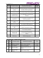
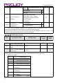
5-1-1.d0Group - Monitoring function group
No. Code
Parameter name
Functional description
Unit
0.
d0.00 Running frequency
Actual output frequency
0.01Hz
1.
d0.01 Set frequency
Actual set frequency
0.01Hz
2.
d0.02 DC bus voltage
Detected value for DC bus
voltage
V
3.
d0.03
Actual output voltage
V
Inverter output
voltage
23
User manual V1.0
No. Code
Parameter name
Inverter output
current
Functional description
Unit
Effective value for Actual motor
current
0.01A
Calculated value for motor
output power
0.1kW
4.
d0.04
5.
d0.05 Motor output power
6.
d0.06 Reserved
7.
d0.07 DI input status
DI input status
-
8.
d0.08 DO output status
DO output status
-
9.
d0.09 AI1 voltage (V)
AI1 input voltage value
0.01V
10.
d0.10 AI2 voltage (V)
AI2 input voltage value
0.01V
11.
d0.11
Panel potentiometer voltage
0.01V
12.
d0.12 Reserved
13.
d0.13 Reserved
14.
d0.14
Motor actual running speed
-
15.
d0.15 PID setting
Reference value percentage when
PID runs
%
16.
d0.16 PID feedback
Feedback value percentage when
PID runs
%
HDI(DI5)High-speed pulse input
frequency display, unit: 0.01KHz
0.01kHz
Remaining run time display, it is
for timing run control
0.1Min
17.
Pd0.18
Panel potentiometer
voltage
Actual operating
speed
HDI(DI5) pulse
frequency
18.
d0.20 Remaining run time
19.
d0.22
20.
21.
22.
24
Current power-on
time
2d0.23 Current run time
6
2
HDI(DI5) pulse
d0.24
7
frequency
2
Communication set
d0.25
8
value
Total time of current inverter
power-on
Min
Total time of current inverter run
0.1Min
HDI(DI5)High-speed pulse input
frequency display, unit: 1Hz
1Hz
Frequency, torque or other
command values set by
communication port
0.01%
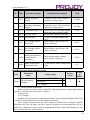
User manual V1.0
No. Code
23.
Parameter name
3
Master frequency
d0.27
1
display
Auxiliary frequency
display
Functional description
Unit
Frequency set by F0.03 master
frequency setting source
0.01Hz
Frequency set by F0.04 auxiliary
frequency setting source
0.01Hz
24.
d0.28
25.
d0.29 Command torque (%) Observe the set command torque
under the torque control mode
Display run, standby and other
d0.35 Inverter status
statuses
1.G type (constant torque load
d0.36 Inverter type
type)
AI1 voltage before
Input voltage value before AI1
d0.37
correction
linear correction
26.
27.
28.
AI2 voltage before
correction
29.
d0.38
30.
Panel potentiometer
d0.39 voltage before
correction
31.
d0.41
motor temperature
inspection value
0.1%
0.01V
Input voltage value before AI2
linear correction
0.01V
Panel potentiometer voltage
before linear correction
0.01V
PT100 inspect motor temperature
value
0℃
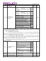
5-1-2.F0 Group -Basic function group
Code
F0.00
Parameter
name
Motor control
manner
Setting range
Vector control W/O PG
0
Reserved
1
Factory
range
Chan
ge
Limit
2
★
2
V/F control
0:Vector control without PG
Refers to the open-loop vector control for high-performance control applications
typically , only one inverter to drive a motor.
1: Reserved
2:V/F control
Suitable for less precision control applications, such as fan and pump loads. Can
be used for an inverter drives several motors occasions.
Note: Vector control mode, the drive capacity and the level of motor capacity
difference can’t be too large, the drive motor can power level than the big two or a
small one, otherwise it may result in degradation of the control performance or the
drive system does not work properly.
25
User manual V1.0
F0.01
Keyboard set
frequency
F0.03
Frequency
source master
setting
0.00Hz to F0.19 (maximum frequency)
0
Frequency setting by Keyboard
(F0.01, UP/DOWN can be 0
modified, power-down without
memory)
Frequency set by Keyboard
(F0.01, UP/DOWN can be
1
modified, power-down without
memory)
Analog AI1 setting
2
Analog AI2 setting
3
Panel potentiometer setting
4
High-speed pulse setting
5
Multi-speed operation setting
Simple PLC program setting
6
PV setting
PID control setting
Remote communications setting
50.0
0Hz
☆
0
★
7
8
9
Select inverter master reference frequency input channels. There are 10 master
reference frequency channels in all:
8: PV setting/PID control setting
( 1 ) Set PV setting, you need to choose 1 or 2 to the E0 group dedicated E0.00
photovoltaic pumping, photovoltaic pump function to be effective. If you do not set E0.00
select 1 or 2, it belongs to the PID control settings.
( 2 ) Selection process PID control output as the operating frequency. Generally
being used for closed-loop control, such as the constant pressure closed-loop control,
constant tension closed-loop control and other occasions.
When adopted the PID as the Frequency source, you need to set the E2 group “PID”
related parameters.
F0.11
F0.13
F0.14
26
Command source
selection
Acceleration time
1
Deceleration time
Keyboard control (LED off)
Terminal block control (LED
on)
Communications
command
control (LED flashes)
Keyboard
control+
Communications
command
control
Keyboard
control+
Communications
command
control+ Terminal block control
0
1
2
0
☆
0.00s to 6500s
-
☆
0.00s to 6500s
-
☆
3
4
User manual V1.0
1
F0.19
F0.20
Maximum output
frequency
Upper limit
frequency source
50.00Hz to 320.00Hz
F0.21 setting
0
Analog AI1 setting
1
Analog AI2 setting
2
Panel potentiometer setting
3
High-speed pulse setting
4
Communication reference
5
50.0
0Hz
★
0
★
Setting upper limit frequency. The upper limit frequency can be set from either
digital setting (F0.21) or analog input channels. If the upper limit frequency is set from
analog input, the set 100% of analog input is relative to F0.21.
To avoid the "Runaway", the setting of upper limit frequency is required, when the
inverter reaches up to the set upper limit frequency value, the inverter will remain
operation at the upper limit frequency, no further increase.
F0.21
Upper limit
frequency
F0.23 (lower limit frequency) to
F0.19(maximum frequency)
50.0
0Hz
☆
F0.23
Lower limit
frequency
0.00Hz to F0.21 (upper limit
frequency)
0.00
Hz
☆
When the frequency command is lower than the lower limit frequency set by F0.23,
the inverter can shut down, and then run at the lower limit frequency or the zero speed;
the running mode can be set by F7.18.
F0.24
Running direction
same direction
opposite direction
0
1
0
☆
By changing the parameters, the motor steering can be achieved without changing
the motor wiring, which acts as the adjustment of any two lines(U, V, W) of the motor to
achieve the conversion of the motor rotation direction.
Note: after the parameter is initialized, the motor running direction will be restored to
its original status. When the system debugging is completed, please use with caution
where the change of motor steering is strictly prohibited.
5-1-3.F1 Input terminals group
Code
F1.00
F1.01
F1.02
F1.03
Parameter name
DI1 terminal
function selection
DI2 terminal
function selection
DI3 terminal
function selection
DI4 terminal function
selection
Setting range
0~51
Factory
range
Chan
ge
Limit
1
★
2
★
0
★
9
★
27
User manual V1.0
F1.04
DI5 terminal function
selection
12
★
F1.05
DI6 terminal function
selection
13
★
F1.06
DI7 terminal function
selection
0
★
F1.07
DI8 terminal function
selection
0
★
Set value
No function
1
Forward run (FWD)
2
Reverse run (REV)
3
Three-wire
control
4
Forward JOG(FJOG)
5
Reverse JOG(RJOG)
6
Terminal UP
7
Terminal DOWN
9
10
Description
The terminal for not use can be set to "no
function" to prevent accidental operation.
0
8
28
Function
operation
External terminals are used to control the
FWD/REV run mode of inverter.
This terminal is used to determine the inverter's
three-wire control mode. For details, please refer
to the instructions of function code F1.10
("terminal command mode).
FJOG means Forward JOG running, RJOG
means Reverse JOG running. For Jog running
frequency and Jog Ac/deceleration time, please
refer to the description of the function code
F7.00, F7.01, F7.02.
Modify
frequency
increment/decrement
command when the frequency is referenced by
external terminal. Adjust up/down the set
frequency when the digital setting is selected as
the frequency source.
Free stop
The inverter output is blocked, at the time, the
parking process of motor is not controlled by the
inverter. This way is same as the principle of free
stop described in F3.07.
Fault reset (RESET)
The function makes use of terminal for fault
reset. It has same function with RESET key on
the keyboard. This function can be used to realize
remote fault reset.
Run pause
The inverter slows down and stops, but all
operating parameters are memorized. Such as
PLC parameters, PID parameters. This terminal
signal disappears, the inverter reverts to the
previous state of running before parking.
User manual V1.0
External fault normally
open input
11
When the signal is sent to the inverter, inverter
trips fault Err.15, and performs troubleshooting
according to fault protection action (details refer
to function code F8.17)
Option 12 ~ 51omitted, If more choices needed, pleasecontact us.
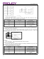
F1.10
Terminal command mode
Two-wire type 1
0
Two-wire type 2
1
Three-wire type 1
2
Three-wire type 2
3
0
★
This parameter defines four different modes to control inverter operation through external
terminals.
0: Two-wire type 1
This mode is the most commonly used two-wire mode. The forward/reverse
operation of motor is determined by terminal DIx, DIy.
The terminal function is set as follows:
Terminals
Set value
Description
DIx
1
Forward run (FWD)
DIy
2
Reverse run (REV)
Of which, DIx and DIy are the multi-function input terminals of DI1 to DI10, the
level is active.
K1
0
K 2 C om m and
0
S top
0
1
REV
1
0
FW D
1
1
S top
K1
K2
D Ix F orw ard(F W D )
D Iy R everse(R E V )
D igital
C O M C om m on
term inals
T w o-w ire m ode 1
1: Two-wire type 2
In the mode, DIx terminal is used as running enabled, while DIy terminal is used to
determine running direction.
The terminal function is set as follows:
Terminals
Set value
Description
DIx
1
Forward run (FWD)
DIy
2
Reverse run (REV)
Of which, DIx and DIy are the multi-function input terminals of DI1 to DI10, the
level is active.
29
User manual V1.0
K1
K2
Command
0
0
Stop
0
1
Stop
1
0
FWD
1
1
REV
K1
DIx
Forward (FWD)
DIy
Reverse (REV)
K2
COM Digital common
Terminals
Two-wire mode
2
2: Three-wire control mode 1
In the mode, DIn is used as enabled terminal, while DIx, DIy terminal are used to
control direction. The terminal function is set as follows:
Terminals
Set value
Description
DIx
1
Forward run (FWD)
DIy
2
Reverse run (REV)
Three-wire operation
DIn
3
control
To run, firstly close DIn terminal, the forward or reverse of motor is controlled by the
ascendant edge of DIx or DIy pulse
To stop, you must disconnect DIn terminal signals Of which, DIx, DIy and DIn are
the multi-function input terminals of DI1 to DI10, DIx and DIy are for active pulse, DIn
is for active level.
SB 2
D Ix
SB 1
Forw ard run
D In T hree-w ire operation
control
D Iy R everse run
SB 3
C O M D igital com m on
term inals
T hree-w ire control m ode 1
Of which:
SB1: Stop button SB2: Forward button SB3: Reverse button
3: Three-wire control mode 2
In the mode, DIn is the enabled terminal, the running commands are given by DIx,
the direction is determined by the state of DIy.
The terminal function is set as follows:
Terminals
Set value
Description
DIx
1
Forward run (FWD)
DIy
2
Reverse run (REV)
Three-wire operation
DIn
3
control
To run, firstly close DIn terminal, the motor run signal is generated by the ascendant
30
User manual V1.0
edge of DIx, the motor direction signal is generated by DIy status
To stop, you must disconnect DIn terminal signals Of which, DIx, DIy and DIn are
the multi-function input terminals of DI1 to DI10, DIx is for active pulse, DIy and DIn
are for active level.
SB2
DIx Forward
SB1
K Command
DIn Three-wire
K
operation
DIy Reverse
COM Digital common
0
FWD
1
REV
Three-wire control mode 2
Of which:
SB1: Stop button
SB2: Run button
F1.12
Minimum input value for
0.00V to F1.14
AIC1
0.00V
☆
F1.13
Corresponding setting for
-100.00% to +100.0%
F1.12
0.0%
☆
F1.14
Maximum input
for AIC1
10.00V
☆
F1.15
Corresponding setting for
-100.00% to +100.0%
F1.14
100.0%
☆
F1.16
Minimum input value for
0.00V to F1.14
AIC2
0.00V
☆
F1.17
Corresponding setting for
-100.00% to +100.0%
F1.16
0.0%
☆
F1.18
Maximum input for
AIC2
10.00V
☆
100.0%
☆
00000
★
F1.19
F1.35
value
F1.12~+100%
F1.12~+100%
Corresponding setting for
-100.00% to +100.0%
F1.18
Single
DI1terminal
digit
activestatus setting
DI terminal valid mode
selection 1
High level active
0
Low level active
1
Tens
digit
DI2 terminal active
status setting (0 to 1,
sames as single digit)
Hund
reds
digit
DI3 terminal active
status setting (0 to 1,
sames as single digit)
Thou
sands
DI4 terminal active
status setting (0 to 1,
31
User manual V1.0
digit
sames as single digit)
Ten
thous
ands
digit
DI5 terminal active
status setting (0 to 1,
sames as single digit)
F1.37
DI1 delay time
0.0s to 3600.0s
0.0s
★
F1.38
DI2 delay time
0.0s to 3600.0s
0.0s
★
F1.39
DI3 delay time
0.0s to 3600.0s
0.0s
★
F1.40
Define the input terminal 0:unrepeatable
repeat
1:repeatable
0
★
5-1-4.F2 Group - Output terminals group
Code
Parameter name
F2.00
SPB terminal
output mode
selection
Setting range
High-speed pulse output
0
Switching quantity output
1
Factory
range
Chan
ge
Limit
0
☆
SPB terminal is a programmable complex terminals, it can be used as an output
terminal of high-speed pulse, also an switching output terminal of collector open circuit.
As a high-speed pulse output, the highest frequency of output pulse is 100kHz,
please see the instructions of F2.06 for high-speed pulse output function.
F2.01
Switching quantity
output function
selection (collector
Open circuit output
terminals)
0 to 40
0
☆
F2.02
Relay 1 output
function selection
(TA1.TB1.TC1)
0 to 40
2
☆
F2.04
SPA output function
selection (collector
Open circuit output
terminals)
0 to 40
1
☆
F2.05
Relay 2 output
function selection
(TA2.TB2.TC2)
0 to 40
1
☆
F2.01
Switching quantity
output function
selection (collector
Open circuit output
terminals)
0 to 40
0
☆
The above five function codes are used to select five digital output functions.
32
User manual V1.0
Multifunction output terminal function is described as follows:
Set
Function
Description
value
0
No output
No output action
The inverter is in operation with output
1
Inverter in service
frequency (zero), and outputs ON signal.
Fault output (fault
When the inverter occurs failure and
2
shutdown)
stops, and outputs ON signal.
Frequency level
Please refer to the instructions of function
3
detection FDT1 output
code F7.23, F7.24
Please refer to the instructions of function
4
Frequency arrival
code F7.25
Outputs ON signal when the inverter is in
Zero speed running
operation with output frequency (zero) Outputs
5
(shutdown without output)
OFF signal when the inverter is in the sate of
stop
Before motor overload protection action,
it will output ON signal if it exceeds the preMotor overload pre6
alarm threshold. Please refer to function code
alarm
F8.02 to F8.04. for motor overload parameter
setting.
Inverter overload preOutputs ON signal within 10s before
7
alarm
inverter overload protection action
Outputs ON signal when the count value
8
Set count value arrival
reaches the value set by E0.08.
Outputs ON signal when the count value
Specified count value
reaches the value set by E0.09. Please refer to
9
arrival
the instructions of Ub group for counting
function.
Outputs ON signal when the detected
10
Length arrival
Actual length exceeds the set length by E0.05.
Outputs a width of 250ms pulse signal
11
PLC cycle completed
when simple PLC completes a cycle
Outputs ON signal when the inverter's
Cumulative running
12
cumulative running time F6.07 exceeds the set
time arrival
time by F7.21.
Outputs ON signal when the rated
frequency exceeds the upper limit frequency or
Frequency being
13
the lower limit frequency, and the output
limited
frequency of inverter also reaches the upper
limit frequency or the lower limit frequency.
Outputs ON signal when the output torque
reaches the torque limit value and the inverter
14
Torque being limited
is in the stall protection status under inverter
speed control mode
Outputs ON signal when the power supply
of the inverter main circuit and control circuit
15
Ready for operation
has stabilized, and the inverter has not any fault
information and is in the runnable status.
33
User manual V1.0
16
17
18
19
20
21
22
Upper limit frequency
arrival
Lower limit frequency
arrival
(shutdown without
output)
Undervoltage status
output
Communication
setting
Reserve
Reserve
23
Zero speed running 2
(shutdown with output)
24
Accumulated poweron time arrival
25
26
27
28
29
30
34
AI1> AI2
Frequency level
detection FDT2 output
Frequency 1 reaches
output value
Frequency 2 reaches
output value
Current 1 reaches
output value
Current 2 reaches
output value
Timer reaches output
value
31
AI1 input exceed limit
32
Load droping
33
Reverse running
34
Zero current status
35
Module temperature
arrival
36
Software current
Outputs ON signal when the value of
analog input AI1 is greater than the AI2 input
value,
Outputs ON signal when the operating
frequency reaches the upper limit frequency,
Outputs ON signal when the operating
frequency reaches the lower limit frequency
Outputs OFF signal when the inverter is in the
state of stop
Outputs ON signal when the inverter is in
the undervoltage condition
Please refer to communication protocol.
Reserve
Reserve
Outputs ON signal when the inverter
output frequency is 0. Outputs ON signal too
when the inverter is in the state of stop
Outputs ON signal when the inverter's
accumulated power-on time(F6.08) exceeds the
set time by F7.20.
Please refer to the instructions of function
code F7.26, F7.27
Please refer to the instructions of function
code F7.28, F7.29
Please refer to the instructions of function
code F7.30, F7.31
Please refer to the instructions of function
code F7.36., F7.37
Please refer to the instructions of function
code F7.38, F7.39
Outputs ON signal when timer(F7.42)is
active and after the inverter's current running
time reaches the set time.
Outputs ON signal when the analog input
AI1 value is greater than F7.51 (AI1 input
protection upper limit) or less than F7.50 (AI1
input protection limit)
Outputs ON signal when the inverter is in
the load drop status.
Outputs ON signal when the inverter is in
the reverse running status.
Please refer to the instructions of function
code F7.32, F7.33
Outputs ON signal when the inverter
module radiator temperature(F6.06)reaches the
set temperature(F7.40).
Please refer to the instructions of function
User manual V1.0
overrun
37
38
Lower limit frequency
arrival(stop with output)
Alarm output
39
Motor
overtemperature prewarning 3
40
Current running time
arrival
F2.06
F2.07
F2.08
High-speed pulse output
function selection
DA1 output function
selection
DA2 output function
selection
code F7.34, F7.35
Outputs ON signal when the operating
frequency reaches the lower limit frequency
Outputs ON signal too when the inverter is in
the sate of stop
When the inverter occurs failure and
continues to run, the inverter alarms output.
When the motor temperature reaches
F8.35 (motor overheat pre-alarm threshold),
the output ON signal. (Motor temperature by
d0.41 view)
Outputs ON signal when the inverter's
current running time exceeds the set time by
F7.45.
0 to 17
0
☆
0 to 17
0
☆
0 to 17
1
☆
High-speed pulse output frequency range is 0.01kHz to F2.09 (maximum frequency
of high-speed pulse output), F2.09 can be set between 0.01kHz to 100.00kHz.
Analog output DA1 and DA2 output range is 0V to 10V, or 0mA to 20mA. The range
of pulse output or analog output and the corresponding calibration relation are shown in
the following table:
Set
Function
Description
value
0
Running frequency
0 to maximum output frequency
1
Set frequency
0 to maximum output frequency
2
Output current
0 to 2 times rated motor current
3
Output torque
0 to 2 times rated motor torque
4
Output power
0 to 2 times rated power
5
Output voltage
High-speed pulse
input
AI1
6
7
8
AI2
9
Reserve
10
Length
11
12
13
Count value
Communication
setting
Motor speed
0 to 1.2 times rated inverter voltage
0.01kHz to 100.00kHz
0V to 10V
0V to 10V (or 0 to 20mA)
0 to maximum set length
0 to maximum count value
0.0% to 100.0%
0
to speed with maximum output
frequency
35
User manual V1.0
14
Output current
15
DC bus voltage
16
17
F2.09
0.0A to 100.0A (inverter power ≦
55kW); 0.0A to 1000.0A (inverter power>
55kW)
0.0V to 1000.0V
Reserve
Frequency source
main set
0~max output frequency
Maximum output
frequency of high-speed
pulse
0.01kHz to 100.00kHz
50.00kHz
☆
SPB terminal is selected as pulse output, the function code is used to select the maximum
value of output pulse.
F2.10
SPB switching quantity
output delay time
0.0s to 3600.0s
0.0s
☆
F2.11
Relay 1 output delay time 0.0s to 3600.0s
0.0s
☆
F2.13
SPA output delay time
0.0s to 3600.0s
0.0s
☆
F2.14
Relay 2 output delay time 0.0s to 3600.0s
0.0s
☆
Set the delay time from occurrence to Actual output for output terminal SPA, SPB,
relay 1, relay 2 and expansion DO.
SPB switching quantity
Units
active status selection
digit
Positive logic
Anti-logic
Tens
digit
F2.15
DO output terminal
active status
selection
Hundr
eds
digit
Thous
ands
digit
Ten
thousa
nds
digit
0
1
Relay 1 terminal active
status setting (0 to 1, as
above)
Expansion D0 terminal
00000
active status setting (0 to 1,
as above)
☆
SPA terminal active status
setting (0 to 1, as above)
Relay 2 terminal active
status setting (0 to 1, as
above)
To define the output logic for output terminal SPA, SPB, relay 1, relay 2 and
expansion DO .0: positive logic : It is active status when the digital output terminal is
connected with the corresponding common terminal, inactive when disconnected; 1: antilogic : It is inactive status when the digital output terminal is connected with the
corresponding common terminal, active when disconnected;
5-1-5.F3 Group - Start and stop control group
Code
36
Parameter name
Setting range
Factory
range
Chan
ge
Limit
User manual V1.0
0
Direct startup
F3.00
Start-up mode
Speed tracking restart
Pre-excitation start
asynchronous motor)
0.00Hz to 10.00Hz
1
(AC
0
☆
0.00Hz
☆
2
F3.03
Start frequency
F3.04
Hold time for start
frequency
0.0s to 100.0s
0.0s
★
F3.05
DCpre-excitation
current
0% to 100%
0%
★
F3.06
DCpre-excitation
time
0.0s to 100.0s
0.0s
★
Start DC braking, generally is used to restart the motor after it stops. Pre-excitation is
used to create magnetic field for asynchronous motor and then start the motor to improve
the response speed.
Start DC braking is only active when the start mode is the direct startup. The inverter
firstly performs DC braking at the set value of DC braking current, after the start DC
braking time is passed, and then start running. If the DC braking time is set to 0, the
inverter will directly start and neglect DC braking. The largerDC braking current, the
greater braking force.
If the startup mode is the asynchronous motor pre-excitation start, the inverter firstly
creates magnetic field at the preset pre-excitation current, after the set pre-excitation time
is passed and then start running. If the pre-excitation time is set to 0, the inverter will
directly start and neglect pre-excitation.
Start DC braking current/pre-excitation current is the percentage of inverter rater
current.
Deceleration parking
0
Free stop
1
F3.07
Stop mode
0
☆
F3.08
Initial frequency of
stop DC braking
0.00Hz to
frequency)
0.00Hz
☆
F3.09
Waiting time of stop
DC braking
0.0s to 100.0s
0.0s
☆
F3.10
Stop DC braking
current
0% to 100%
0%
☆
F3.11
Stop DC braking time
0.0s to 100.0s
0.0s
☆
F0.19
(maximum
5-1-6.F4 V/Fcontrol group
Code
Parameter name
F4.00
V/F mode setting
Setting range
Line V/F
0
Multi-point V/F
1
Factory
range
Cha
nge
Lim
it
0
★
37
User manual V1.0
F4.01
F4.02
F4.09
Square V/F
2
1.2 square V/F
3
1.4 square V/F
4
1.6 Square V/F
6
1.8 Square V/F
8
V/F complete separeation
10
11
V/F half separeation
0.0%: Automatic torque boost
0.1%~30.0%
Torque boost
Torque boos cutoff
frequency
Slip compensation
gain
0.00Hz
~
frequency )
F0.19(Maximum
0.0 %~200.0%
4%
★
15.00Hz
★
0.0%
☆
This parameter is valid only for asynchronous motors.
V/F slip compensation can compensate for the speed deviation of asynchronous motor
when the increases, so as to keep stable speed when the load changes.
If V/F slip compensation gain is set to 100.0%, it means that the compensated
deviation is equal to the rated motor slip under the rated motor load, while the rated motor
slip can be calculated through b0 group of motor rated frequency and rated speed.
When adjust V/F slip compensation gain, generally it is based on the principle that the
motor speed is same as the target speed. When the motor speed is different from target
value, it is necessary to appropriately fine-tune the gain.
F4.10 V/F overexcitation gain
F4.11
V/F oscillation
suppression gain
0 to 200
64
☆
0 to 100
-
☆
5-1-7.F6 Keybaord and Display
Code
F6.00
F6.01
38
Parameter name
STOP/RESET key is
enabled
only
under
keyboard mode operation
STOP/RESET key is
enabled under any mode
of operation
STOP/RESET
Functions
Running
display 1
Setting range
status
0000 ~FFFF
Factory
range
Chan
ge
Limit
1
☆
001F
☆
0
1
User manual V1.0
15 14 13 12 11 10
9
8
7
6
5
4
3
2
1
0
Running frequency (Hz)
Set frequency
(Hz)
Bus voltage
(V)
Output voltage
(V)
(A)
Output current
(kW)
Output power
(%)
Output torque
DI Input status
DO Output
AI1 Voltage (V)
AI2 Voltage(V)
Reserve
Count
Length
Load speed
PID Setting
If the above parameters need to be displayed in operation, firstly set its position to 1, and
then set at F6.01 after converting the binary number to the hexadecimal number.
F6.03
Stop status display
15 14 13 12 11 10 9 8
0033
0000~FFFF
☆
7 6 5 4 3 2 1 0
Setting frequency(Hz)
Bus voltage
(V)
DI input situation
DO output situation
(V)
AI1 voltage
AI2 voltage
(V)
Remain
Count value
Length
PLC range
Load speed
PID setting
High speed pulse
input frequency(Hz)
Remain
Remain
Remain
If the above parameters need to be displayed on operation, firstly set its position to 1, and
then set at F6.03 after converting the binary number to the hexadecimal number.
F6.06
Inverter module
radiator temperature
-
0.0℃ to 100.0℃
●
Display the inverter module IGBT temperature
The different models of the inverter module vary IGBT overtemperature protection
values.
F6.07
Total run time
-
0h to 65535h
●
Display the total run time of inverter When the run time reaches the set time(F7.21),
the inverter's multi-function digital output function (12) outputs ON signal.
F6.08
Total power-on time
-
0 to 65535 h
●
Display the total power-on time of inverter.
When the total power-on time reaches the set power-on time F7.21, inverter’s multifunction digital output function (24) output ON signal.
F6.10
Part number
Inverter product number
F6.11
Software version
number
F6.15
Keyboard type
selection
Control panel software version
number
0:keypad (single row LED)
1:big keyboard (double row LED)
F6.16
Monitor selection 2
1Kbit/100bit
10bit/1bit
parameter
number
parameter
series number
-
●
-
●
0
●
d0.04
●
39
User manual V1.0
The parameter of motor selection2 can be showed in the bottom of double LED
or LCD
Power
correction
F6.17
0.00~10.00
1.00
☆
coefficient
Frequency converter with motor running, the display output power(d0.05)is
different with the actual output power, through the parameters, adjust the converter
display power and the actual output power corresponding relation.
5-1-8.F7 Group - Auxiliary function group
Code
Setting range
Factory
range
Chan
ge
Limit
0.00Hz to F0.19 (maximum
frequency)
2.00Hz
☆
Parameter name
F7.00
Jog
frequency
running
F7.01
Jog acceleration time
0.0s to 6500.0s
20.0s
☆
F7.02
Jog deceleration time
0.0s to 6500.0s
20.0s
☆
F7.17
Reverse rotation
control
Allow
0
Prohibit
1
0
☆
F7.22
Start protection
OFF
0
ON
1
0
☆
This parameter relates to the security features of the inverter
If this parameter is set to 1 , and if the running command is active (e.g. the terminal
running command is closed before power-on) when the inverter is in power-on, the
inverter will not respond to the running command, you must firstly cancel the running
command, when the running command is active again, the inverter will respond.
In addition, if the parameter is set to 1, and if the running command is active when
the inverter resets fault, the inverter will not respond to the running command, you must
firstly cancel the running command in order to eliminate running protection status.
The parameter is set 1, you can prevent the danger caused by that the inverter
unknowingly responds to the running command in the event of power-on and fault reset.
5-1-9.F8 Group - Fault and protection
Code
Parameter name
F8.00
Overcurrent stall gain
F8.01
Overcurrent
protection current
stall
Setting range
Factory
range
0 to 100
20
Chan
ge
Limit
☆
100% to 200%
150%
☆
In the process of the inverter acceleration, when the output current exceeds the
overcurrent stall protection current, the inverter stops ac/deceleration process and remains
in the current operating frequency, and then continues to ac/decelerate upon the decline of
the output current.
Overcurrent stall gain is used for adjusting inhibition overcurrent capability during
ac/deceleration. The greater this value, the stronger inhibition overcurrent capability
Under the premise that the overcurrent does not occur, the best is the smaller gain setting.
For the small inertia load, the overcurrent stall gain should be small, otherwise which
40
User manual V1.0
cause the slower system dynamic response. For the big inertia load, the overcurrent stall
gain should be large, otherwise the poor inhibitory effect may cause overcurrent fault.
When the overcurrent stall gain is set to 0, the overcurrent stall function will be
canceled.
F8.02 Motor overload protection
F8.03
Motor overload protection
gain
Prohibit
0
Allow
1
0.20 to 10.00
1
☆
1.00
☆
F8.02 = 0: no motor overload protection function, there may be the risk of damage to
the motor due to overheating, it is recommended that the thermal relay is installed
between the inverter and the motor;
F8.02 = 1: the inverter will determine whether the motor is overloaded or not
according to the inverse time curve of motor overload protection. Inverse time curve of
motor overload protection: 220% x (F8.03) x rated motor current, if this lasts for 1
second, the alarm of motor will be prompted overload fault; 150% x (F8.03) × rated motor
current, if this lasts for 60 seconds, the alarm of motor overload will be prompted.
User shall correctly set the value of F8.03 according to the Actual motor overload
capacity, if the value is set to too large , which may easily lead to motor overheating and
damage while the inverter will not alarm!
F8.04 Motor overload pre-alarm
coefficient
80%
50% to 100%
☆
This function is used in the front of motor overload fault protection, and sends a prealarm signal to the control system by DO. The warning coefficient is used to determine
the extent of pre-alarm prior to motor overload protection. The higher the value, the
smaller the extent of pre-alarm in advance.
When the cumulative amount of inverter output current is greater than the product of
the inverse time curve of overload and F8.04, the inverter multi-function digital DO will
output "Motor Overload Pre-Alarm" ON signal.
F8.05 Overvoltage stall gain
0 (no overvoltage stall) to 100
Overvoltage stall protection
F8.06 voltage
/
energy
consumption brake voltage
120% to 150%(three-phase)
0
☆
130%
☆
In the process of the inverter deceleration, when the DC bus voltage exceeds the
overvoltage stall protection voltage/the energy consumption brake voltage, the inverter
stops deceleration and maintains at the current operating frequency(if F3.12 is not set to 0,
the braking signal is outputted the energy consumption brake can be implemented by an
external braking resistor.) and then continues to decelerate upon decline of the bus voltage
Overvoltage stall gain is used for adjusting inhibition overvoltage capability during
deceleration. The greater this value, the stronger inhibition overvoltage capability under
the premise that the overvoltage does not occur, the best is the smaller gain setting.
For the small inertia load, the overvoltage stall gain should be small, otherwise which
cause the slower system dynamic response. For the big inertia load, the overvoltage stall
gain should be large, otherwise the poor inhibitory effect may cause overvoltage fault.
When the overvoltage stall gain is set to 0, the overvoltage stall function will be
canceled.
F8.08 Output phase loss protection
Prohibit
0
1
☆
41
User manual V1.0
selection
Allow
1
Select whether the output phase loss protection is done or not.
F8.09 Power-on short circuit to
ground
Invalid
0
Valid
1
1
☆
You can detect whether the motor is shorted to ground when the inverter is powered
on.
If this function is active, the inverter's UVW terminal will output voltage after poweron for a while.
F8.10 Number of automatic fault
reset
0
0 to 32767
☆
When the inverter selects automatic fault reset, it is used to set the number of times
of automatic fault reset. If the set number of times is exceeded, the inverter remains a
failed state.
When set F8.10 (number of automatic fault reset) ≥ 1, inverter will run
automatically when repower after instantaneous power-off.
When fault self-recovery restart uptime over an hour later, it will restore the original
setting of automatic fault reset.
F8.11
Fault DO action selection
during automatic fault reset
OFF
0
ON
1
0
☆
If the inverter automatic fault reset function is set, F8.10 can be used to set whether
DO action is active or not during the automatic fault reset
F8.12 Automatic
interval
fault
reset
0.1s to 100.0s
1.0s
☆
0
☆
It is the waiting time from the inverter fault alarm to automatic fault reset.
0
protection Invalid
1
Valid
drop detection 0.0% to 100.0% (rated motor
current)
drop detection 0.0s to 60.0s
F8.30 Load drop
selection
F8.31 Load
10.0% ☆
level
F8.32 Load
1.0s
☆
time
If the
load drop protection function is active, when the inverter output current is less
than the load drop detection level (F8.31)and the duration is longer than the load drop
detection time(F8.32), the inverter output frequency is automatically reduced to 7% of the
rated frequency. During the load drop protection, if the load recovers, the inverter
automatically resumes to the set frequency to run.
5-1-10.F9 Group - Communication parameter
Code
F9.00
42
Parameter name
Baud rate
Setting range
Units
digit
300BPS
600BPS
Facto
ry
range
Chan
ge
Limit
6005
☆
MODBUS
0
1
User manual V1.0
1200BPS
2
2400BPS
3
4800BPS
4
9600BPS
5
19200BPS
6
38400BPS
7
57600BPS
8
115200BPS
9
Tens
Profibus-DP
digit
115200BPS
0
208300BPS
1
256000BPS
2
512000BPS
3
Hundre
ds digit
Thousan
ds digit
20
F9.01
Data format
Reserve
CAN bus baudrate
0
50
1
100
2
125
3
250
4
500
5
1M
6
No parity (8-N-2)
0
Even parity (8-E-1)
1
Odd parity (8-O-1)
2
No parity(8-N-1)
3
0
☆
1
☆
F9.02
This unit address
1 to 250, 0 for broadcast address
F9.03
Response delay
0ms-20ms
2ms
☆
F9.04
Communication
timeout time
0.0 (invalid), 0.1s-60.0s
0.0s
☆
Data transfer format
selection
Units
MODBUS
digit
Non-standard
MODBUS
protocol
Standard MODBUS protocol
30
☆
F9.05
0
1
43
User manual V1.0
F9.06
F9.07
Current
ratio
resolution
Communication
card type
Tens
Profibus
digit
PPO1 format
0
PPO2 format
1
PPO3 format
2
PPO5 format
3
0.01A
0
0.1A
0:Modbus communication
card
1:Profibus
communication
card
2:Reserved
3:CAN bus communication
card
1
0
☆
0
☆
0
1
2
3
5-1-11.FB Group - Control optimization parameters
Code
Parameter name
FB.00
Fast current limiting
manner
Setting range
Disable
0
Enable
1
Factory
range
Chan
ge
Limit
1
☆
Enable Quick Current Limiting function, which can minimize the overcurrent fault of
inverter , and ensure the uninterrupted operation of inverter. If the drive is in the state of
fast current limiting for a long period of time , the inverter may be damaged by
overheating and others, this case is not allowed, so the inverter will alarm fault with fault
ID Err.40, it indicates that the inverter exists overload and needs to be shut down.
FB.01
Undervoltage point
setting
100.0%
50.0% to 140.0%
☆
Used to set the voltage value of inverter undervoltage fault with fault ID Err.09 , the
different voltage levels of inverter 100.0% corresponds to the different voltage points are
as follows:
Single-phase 220V or three-phase 220V: 200V three-phase 380V: 350V
Three-phase 480V: 450V three-phase 690V: 650V
FB.02
Overvoltage point
setting
FB.03
Deadband
compensation
mode selection
FB.04
Current detection
compensation
200.0V to 2500.0V
No compensation
0
Compensation mode 1
1
Compensation mode 2
2
0 to 100
5-1-12.E0 Solar water pump special group
44
810V
☆
1
☆
5
☆
User manual V1.0
Code
Parameter name
E0.00
Solar
operation
mode selection
Setting range
Control mode invalid
CVT Mode
MPPT Mode
0
1
2
Factory
range
Chan
ge
Limit
0
☆
0: PV invalid
Photovoltaic effect does not work; when normal operation model, need to set E0.00=0.
1: CVT mode
Bus voltage is constant as a given value, F0.03 is set to 8, photovoltaic mode, bus
voltage is given as E0.01, feedback the current bus voltage.
2: MPPT mode
Bus voltage is given as the maximum power search result, F0.03 is set to 8, photovoltaic
mode. When starting but before the searching, the bus voltage is given as E0.01, at
intervals after the search, the search result is as given value.
E0.01
Solar
setting
voltage
0.0~1000.0V
Confirmed
model type
☆
When set E0.00 to 1, this voltage is CVT mode bus voltage set value;
When set E0.00 to 2, the voltage is the bus voltage given value when MPPT mode be
started, and also the initial value when search voltage.
Appropriate adjustments according to the site conditions.
Note: the set value should be lower than the bus voltage value, if the value is higher than
the bus voltage, the inverter may run at around 0Hz during starting.
E0.02
MPPT
search
time
Voltage
interval
0.0~1000.0S
30.0S
☆
MPPT Interval search time when set E0.00 to 2. It indicates the speed of MPPT
tracking ,lower numbers equate to better speed on MPPT tracking,but the MPPT
serching interval is short,may result in more fluctuations on output frequency of the
inverter.
E0.03
MPPT
Voltage
step length
0.0~1000.0V
10.0V
☆
Confirmed
model type
☆
Confirmed
model type
☆
20.0V
☆
Voltage step searching by MTTP when set E0.00 to 2
E0.04
Upper limit of
MPPT
search
voltage
0.0~1000.0V
Upper limit value during MPPT voltage searching
E0.05
Lower limit of
MPPT
search
voltage
0.0~1000.0V
Lower limit value during MPPT voltage searching
E0.06
PID
Maximum
voltage deviation
value
0.0~1000.0V
When Photovoltaic mode works, by changing parameters, can limit given bus voltage
and current bus voltage’s PID maximum input voltage deviation value.
45
User manual V1.0
E0.07
Solar
voltage
wake
0.0~1000.0V
Confirmed
model type
☆
When inverter into hibernation, if the bus voltage gradually higher than the set voltage
(E0.07), the inverter will start automatically.
E0.08
Solar hibernation
voltage
0.0~1000.0V
Confirmed
model type
☆
When inverter is running, when the bus voltage is lower than the set voltage (E0.08),
inverter will go into hibernation.
E0.09
E0.10
Minimum identify
value of changing
power
Load
drop
detection interval
time
0~65536W
0~65535s
8W
☆
6000s
☆
After the load drop fault, inverter will restart after this setting time (E0.10).
5-1-13.E2 PID Function Group
0
Chan
ge
Limit
☆
50.0%
☆
0~8
0
☆
PID action direction
0:positive;1:negative
0
☆
E2.04
PID Reverse cutoff
frequency
0~65535
1000
☆
E2.05
PID
setting
feedback range
0 . 00 ~ F0.19(Max.
frequency)
2.00Hz
☆
E2.06
PID Deviation limit
0.0%~100.0%
0.0%
☆
Code
Parameter name
Setting range
E2.00
PID setting source
0~6
E2.01
PID
setting
0.0%~100.0%
E2.02
PID feedback source
E2.03
keyboard
Factory
range
When the deviation of PID given value and feedback value is smaller than E2.06, PID
will stop regulating action, so the output frequency keeps steady, it is quite effective for
some close-loop control applications.
E2.07
PID Differential limit 0.00%~100.00%
0.10%
☆
Differentiation is a very sensitive role in PID regulator, it is easy to cause the system
oscillation, therefore, generally need to limit it in a small range, E2.07 is used to set the
range of PID differential outputs.
E2.08
PID reference change
time
0.00s~650.00s
0.00s
PID reference change time, is the time of PID given value changes from 0.0% to
46
☆
User manual V1.0
100.0%.
When PID given value changes, PID given value changes lineal in accordance with a
given reference change time, reduce the adverse effects to the system.
E2.09
PID feedback filter
time
E2.10 PID output filter time
0.00s~60.00s
0.00s
☆
0.00s~60.00s
0.00s
☆
E2.09 is for PID feedback value filtering, the filter help to reduce the impact on the
amount of feedback is interference, but the process will bring the affect the responding
performance of closed-loop system.
E2.10 is for PID output frequency filtering, the filter will diminish the mutation of
output frequency, but the same process will bring the performance of closed-loop system
response decreased.
E2.11
PID feedback loss
detection value
0.0% : not judging feedback
loss
0.1%~100.0%
0.0%
☆
E2.12
PID feedback loss
detection time
0.0s~20.0s
0.0s
☆
This function code is used to determine whether the PID feedback is loss.
When the amount is less than the E2.11 value, and duration is longer than E2.12 value,
inverter will alarm Err.31 fault, and process trouble-shooting according to the fault.
E2.13 Proportional gain KP1 0.0~200.0
80.0
☆
E2.14
Integration time Ti1
0.01s~10.00s
0.50s
☆
E2.15
Differential time Td1
0.00s~10.000s
0.000s
☆
Proportional gain KP1: determine the intensity of the entire PID regulator, the bigger
KP1 value, the greater regulation intensity. When set it to100.0 means that when the
deviation of PID feedback value and a given value is 100.0%, PID controller for adjusting
the amplitude of output frequency command is the maximum frequency.
Integration time Ti1: determine the integral regulator intensity of PID regulator. The
shorter Ti1 time, the great regulation intensity, adjustment intensity. Integration time
means when the PID feedback value and a given value deviation is 100.0%, integral
regulator continuously adjusts to reach the maximum frequency.
Differential time Td1: determine the intensity of PID regulator to adjust the deviation
rate. The longer differential Td1 time, the greater regulator intensity. Differential time is
when the feedback value change 100.0% within this time, the regulation value of the
deviation regulator is maximum frequency.
E2.16 Proportional gain KP2 0.0~200.0
20.0
☆
E2.17
Integration time Ti2
0.01s~10.00s
2.00s
☆
E2.18
Differential time Td2
0.00s~10.000s
No switch action
0.000s
☆
0
Switch via DI terminal
1
Switch automatically according
to the deviation
0
☆
2
E2.19
Parameter switching
conditions
47
User manual V1.0
E2.20
PID
parameter
0.0%~E2.21
switching deviation 1
20.0%
☆
E2.21
PID
parameter
E2.20~100.0%
switching deviation 2
80.0%
☆
In some applications, one set of PID parameters can not meet the needs of the entire
operation, so need to adopt different PID parameters under different circumstances.
This group parameters are used for switching two sets of PID parameters. The way of
setting of regulator parameters E2.16 ~ E2.18 are similar to the parameters E2.13 ~ E2.15.
Two sets of PID parameters can be switched by multi-functional digital terminals DI,
and also can be switched automatically according to the PID deviation.
When DI multi-functional terminal selected, multi-function terminal function to be set
to 43 (PID parameter switching terminal), select the parameter 1 (E2.13 ~ E2.15) when
the terminal is invalid, select the parameter 2 when the terminal is valid (E2.16 ~ E2.18).
When automatic switch selected, when the deviation absolute value of “given value”
and “feedback value” is smaller than E2.20, PID parameter select parameter group 1.
when the deviation absolute value of “given value” and “feedback value” is bigger than
E2.21, PID parameter select parameter group 2. And when the deviation absolute value is
between E2.20 and E2.21, PID parameter will be the interpolation value of the two
parameter groups, please refer to diagram.
Unit
Integral separation
digit
invalid
E2.22 PID integral nature
0
Valid
1
Ten
Whether to stop integration
digit
when output reach limit
Continue integration
0
Stop integration
00
☆
1
Integral separation:
If set integral separation valid, when multi-function digital terminals DI integral pause
(function 38) is valid, PID integration stop operation, then only PID proportional and
differential action are effective.
If set integral separation invalid, whether DI is effective or not, integral separation are
invalid.
Whether to stop integration when output reach limit: After the PID outputs reaches the
maximum or minimum value, can choose whether to stop the integral action. If choose to
stop integration, PID integration stops, which may help reduce the PID over-regulation
value.
E2.23
PID initial value
0.0% ~ 100.0%
frequency)
E2.24
PID initial value
hold time
0.00s~360.00s
(
maximum
0.0%
☆
0.00s
☆
When inverter starts, PID output is fixed as the initial value E2.23, after continued
E2.24 hold time, PID starts to regulation operations of close loop.
E2.25
48
Maximum deviation
0.00%~100.00%
1.00%
☆
User manual V1.0
value (forward)
E2.26
Maximum deviation
value (reverse)
0.00%~100.00%
1.00%
☆
This function is used to limit the deviation between the two PID output shot (2ms /
beat), in order to suppress excessive PID output, to make the inverter running stable.
E2.25 corresponds to the maximum value of absolute output deviation of forward running,
E2.26 corresponds to the maximum value of absolute output deviation of reverse running.
5-1-14.E3 Virtual terminal group
E3.00
VDI1 function selection
0~50
0
Chan
ge
Limit
★
E3.01
VDI2 function selection
0~50
0
★
E3.02
VDI3 function selection
0~50
0
★
E3.03
VDI4 function selection
0~50
0
★
E3.04
VDI5 function selection
0~50
0
★
Code
Parameter name
Setting range
Factory
range
Virtual VDI1 ~ VDI5 functionally identical DI on control board, it can be used as a
multi-function digital inputs, detailed settings please refer to introduction of F1.00 ~
F1.09.
Units digit
Virtual VDI1
0
invalid
valid
Tens digit
E3.05
Virtual
VDI
terminal status set
Hundreds digit
Thousands digit
Tens of thousands
digit
E3.06
Virtual
VDI
terminal effective
status set mode
1
Virtual VDI2( 0
to 1, same as
above)
Virtual VDI3( 0
to 1, same as
above)
Virtual VDI4( 0
to 1, same as
above)
Virtual VDI5( 0
to 1, same as
above)
Virtual VDI1
Units digit
ddddigit:Virtual
VD1 whether valid is decided
by Virtual VDOX status
VD1 whether valid is decided
by E3.05
Tens digit
0
00000
★
11111
★
1
Virtual VDI2(0
49
User manual V1.0
Hundreds digit
Thousands digit
Tens of thousands
digit
to 1, same as
above)
Virtual VDI3(0
to 1, same as
above)
Virtual VDI4(0
to 1, same as
above)
Virtual VDI5(0
to 1,same as
above)
Different from ordinary digital quantity input terminals, virtual VDI state can have
two setting modes which is selected by E3.06.
When selecting VDI state is determined by the state of the corresponding virtual VDO,
VDI is valid or invalid state depending on the VDO output valid or invalid, and VDIx
only binding VDOx(x=1~5)
When choosing VDI state selection function code to set, through the binary bits of E3.05,
respectively determine the state of virtual input terminals.
Example of how to use VDI.
Example 1. Implement following function: “Inverter fault alarm and shuts down when AI1
input exceeds upper or lower frequency” .
Realize by following settings: Set VDI state decided by VDO, set VDI1 function as “ user
defined fault 1” (E3.00=44); set VDI1 terminal state effective mode decided by VDO1
(E3.06=xxx0); set VDO1 output function as “AI1 input exceeds upper & lower
frequency” (E3.11=31); so when AI1 input exceeds upper or lower frequency, VDO1 state
is ON, VDI1 input terminal state is effective, VDI1 receive user defined fault 1, inverter
then alarm fault no. 27 and shuts down.
Example 2. Implement following function: “Inverter run automatically after power-on”.
Realize by following settings: set VDI state decided by function code E3.05, set VDI1
function as “FORWARD” (E3.00=1); set VDI1 terminal state effective decided by
function code (E3.06=xxx1); set VDI1 terminal state is effective (E3.05=xxx1); set
command source as “terminal control” (F0.11=1); set protection selection as “no
protection” (F7.22=0); so after inverter powered on and initialization complete, VDI1
detected effective, and it match forward running, then inverter starts running forwardly.
E3.07
AI1 terminal as a
function selection
of DI
0 to 50
0
★
E3.08
AI2 terminal as a
function selection
of DI
0 to 50
0
★
E3.09
Panel
potentiometer as a
function selection
of DI
0 to 50
0
★
E3.10
Effective
mode
selection when AI
Units
AI1
digit
High level effectively
000
★
50
0
User manual V1.0
as DI
Low level effectively
1
Tens
AI2(0 to 1,same as units digit)
digit
Hund
Panel potentiometer (0 to
reds
1,same as units digit)
digit
This group function code is used when using AI as DI, when AI used as DI, and input
voltage of AI is greater than 7V, AI terminal status will be high level, when input voltage
of AI is lower than 3V, AI terminal status will be low level. For between 3V~ 7V
hysteresis E3.10 is to determine that when the AI is used as DI, AI is made valid by means
of the high level state, or the low level of valid states. As for AI as DI feature set, same as
the ordinary DI Settings, please refer to the F1 group setting instructions related DI.
E3.11
E3.12
E3.13
E3.14
E3.15
E3.16
Virtual VDO1
output function
selection
Virtual VDO2
output function
selection
Virtual VDO3
output function
selection
Virtual VDO4
output function
selection
Virtual VDO5
output function
selection
VDO
output
terminal effective
status selection
With the physical internal
sub DIx
See F2 group physical DO
output option
With the physical internal
sub DIx
See F2 group physical DO
output option
With the physical internal
sub DIx
See F2 group physical DO
output option
With the physical internal
sub DIx
See F2 group physical DO
output option
With the physical internal
sub DIx
See F2 group physical DO
output option
Units
VDO1
digit
Positive logic
0
0
☆
0
☆
0
☆
0
☆
0
☆
00000
☆
1to40
0
1to40
0
1to40
0
1to40
0
1to40
0
Negative logic
1
Tens
VDO2(0 to 1,same as above)
digit
Hund
reds
VDO3(0 to 1,same as above)
digit
Thou
sands VDO4(0 to 1,same as above)
digit
Tens VDO5 ( 0 to 1,same as
51
User manual V1.0
of
above)
thous
ands
digit
0.0s to 3600.0s
0.0s
☆
0.0s to 3600.0s
0.0s
☆
0.0s to 3600.0s
0.0s
☆
0.0s to 3600.0s
0.0s
☆
0.0s to 3600.0s
E3.21 delay
VDO5time
output
delay time
5-1-15.b0 Motor parameters group
0.0s
☆
E3.17
E3.18
E3.19
E3.20
Code
b0.00
VDO1 output
delay
VDO2time
output
delay
VDO3time
output
delay
VDO4time
output
Parameter name
Motor type
selection
b0.01
Rated power
b0.02
Rated voltage
b0.03
Rated current
b0.04
Rated frequency
b0.05
Rated speed
Setting range
General
asynchronous
motor
Asynchronous
inverter
motor
Permanent
magnet
synchronous motor
0.1kW to 1000.0kW
Factory
range
Chan
ge
Limit
0
★
-
★
-
★
-
★
-
★
-
★
0
1
2
1V to 2000V
0.01A to 655.35A (inverter
power ≦ 55kW)
0.1A to 6553.5A (inverter rate>
55kW)
0.01Hz to F0.19 (maximum
frequency)
1rpm to 36000rpm
Above b0.00 to b0.05 are the motor nameplate parameters, which affects the
accuracy of the measured parameters. Please set up according to the motor nameplate
parameters. The excellent vector control performance needs the accurate motor
parameters. The accurate identification of parameters is derived from the correct setting of
rated motor parameters.
In order to guarantee the control performance, please configure your motor according
to the inverter standards, the motor rated current is limited to between 30% to 100% of the
inverter rated current. The motor rated current can be set, but can not exceed the inverter
rated current. This parameter can be used to determine the inverter's overload protection
capacity and energy efficiency for the motor.
It is used for the prevention of overheating caused by the self-cooled motor at low
speed , or to correct for protecting the motor when the little change of the motor
characteristics may affect the changes of the motor capacity.
b0.06
52
Asynchronous
motor stator
resistance
0.001Ω to 65.535Ω (inverter
power <= 55kW)
0.0001Ω to 6.5535Ω (inverter
power> 55kW)
-
★
User manual V1.0
b0.07
Asynchronous
motor rotor
resistance
b0.08
Asynchronous
motor leakage
inductance
b0.09
Asynchronous
motor mutUal
inductance
b0.10
Asynchronous
motor no-load
current
0.001Ω to 65.535Ω (inverter
power <= 55kW)
0.0001Ω to 6.5535Ω (inverter
power> 55kW)
0.01mH to 655.35mH (inverter
power <= 55kW)
0.001mH to 65.535mH (inverter
power> 55kW)
0.01mH to 655.35mH (inverter
power <= 55kW)
0.001mH to 65.535mH (inverter
power> 55kW)
0.01A to b0.03 (inverter power <=
55kW)
0.1A to b0.03 (inverter power>
55kW)
-
★
-
★
-
★
-
★
b0.06 to b0.10 are the asynchronous motor parameters, and generally these
parameters will not appear on the motor nameplate and can be obtained by the inverter
auto tunning. Among which, only three parameters of b0.06 to b0.08 can be obtained by
Asynchronous Motor Parameters Still Auto Tunning; however, not only all five
parameters but also encoder phase sequence and current loop PI parameters can be
obtained by Asynchronous Motor Parameters Comprehensive Auto Tunning
When modifying the motor's rated power (b0.01) or rated voltage (b0.02), the
inverter will automatically calculate and modify the parameter values of b0.06 to
b0.10 , and restore these 5 parameters to the motor parameters of commonly used standard
Y Series.
If the asynchronous motor parameters auto tunning can not be achieved on-site, you
can enter the corresponding above parameters according to the parameters provided by the
manufacturer.
b0.27
Motor parameter
auto tunning
No operation
Asynchronous
motor
parameters still auto tunning
Asynchronous
motor
parameters comprehensive auto
tunning
0
1
0
★
2
If the motor is able to disengage the load, in order to obtain a better operating
performance, you can choose comprehensive auto tunning; otherwise, you can only select
parameters still auto tunning. Firstly set the parameter according to load condition, and
then press RUN key, the inverter will perform parameters auto tunning. Parameters auto
tunning can be performed only under keyboard operation mode, is not suitable for
terminal operation mode and communication operation mode.
0: no operation, which prohibits parameters auto tunning.
1: asynchronous motor parameters still auto tunning
Motor type and motor nameplate parameters b0.00 to b0.05 must be set correctly
before performing asynchronous motor parameters still auto tunning. The inverter can
obtain b0.06 to b0.08 three parameters before performing asynchronous motor parameters
still auto tunning.
53
User manual V1.0
2: asynchronous motor parameters comprehensive auto tunning
During asynchronous motor parameters comprehensive auto tunning, the inverter
firstly performs parameters still auto tunning, and then accelerates up to 80% of the rated
motor frequency according to the acceleration time F0.13, after a period of time, and then
decelerates till stop according to the deceleration time F0.14 to end auto tunning.
Before preforming asynchronous motor parameters comprehensive auto tunning, not
only motor type and motor nameplate parameters b0.00 to b0.05 must be set properly, but
also encoder type and encoder pulses b0.29, b0.28.
For asynchronous motor parameters comprehensive auto tunning, the inverter can
obtain b0.06 to b0.10 five motor parameters, as well as the AB phase sequence b0.31 of
encoder, vector control current loop PI parameters F5.12 to F5.15.
5-1-16.y0 Function code management group
Code
y0.00
Parameter name
Parameter
initialization
Setting range
No operation
Restore
the
factory
parameters, not including
motor parameters
Clear history
Restore default parameter
values, including motor
parameters
Backup
current
user
parameters
Restore
user
backup
parameters
Clear keyboard storage
area
upload
parameter
to
keyboard storage area 1
upload
parameter
to
keyboard storage area 2
download the parameters
from keyboard storage 1
area to the storage system
download the parameters
from keyboard storage 2
area to the storage system
Factory
range
Chan
ge
Limit
0
★
0
1
2
3
4
50
1
10
11
12
21
22
1: restore the factory setting, not including motor parameters
After y0.00 is set to 1, most of the inverter function parameters are restored to the
factory default parameters, but motor parameters, frequency command decimal point
(F0.02), fault recording information, cumulative running time , cumulative power-on
time and cumulative power consumption will not be restored.
2: clear history
To clear the history of the inverter's fault recording information, cumulative running
54
User manual V1.0
time , cumulative power-on time and cumulative power consumption
3: restore default parameter values including motor parameters
4: backup current user parameters
Backup the parameters set by the current user. Backup all function parameters. It is
easy to restore the default settings when user incorrectly adjust parameters.
501, Restore user backup parameters
Restore previous backup user parameters.
10: Clear keyboard storage area
Empty keyboard storage area 1 and keyboard storage area 2
11: upload parameter to keyboard storage area 1
Upload the parameters of the inverter to keyboard storage area 1
12: upload parameter to keyboard storage area 2
Upload the parameters of the inverter to the keyboard storage area 2
21: download the parameters from keyboard storage 1 area to the storage system
Download the parameters from keyboard storage 1 to inverter
22:download the parameters from keyboard storage 2 area to the storage system
Download the parameters from keyboard storage 2 to inverter
y0.01
User password
0
0 to 65535
☆
When y0.01 is set to one any non-zero number, the password protection will take
effect. You enter the menu for the next time, you must enter the password correctly,
otherwise can not view and modify the function parameters, please keep in mind the set
user password.
When y0.01 is set to 0, the set user password will be cleared, the password protection
function is invalid.
Units
d group display selection
digit
Not display
0
Display
1
Tens
E group display selection
digit
Not display
0
Display
y0.02
Function parameters
display properties
Hund
reds
digit
1
b group display selection
Not display
0
Display
1
Thou
sands
digit
y1
group
selection
★
display
Not display
0
Display
1
Tens
thous
11111
L group display selection
55
User manual V1.0
ands
digit
y0.03
User Parameters
display
y0.04
Function
modification
properties
code
Not display
0
Display
Units digit: Reserved
Tens digit :User’s change
parameter display selection
0:not displays
1:displays
1
Modifiable
0
Not modifiable
1
00
☆
0
☆
User can set whether function code parameter can be modified or not, so as to
prevent the risk that function parameters are altered unexpectedly.
If the function code is set to 0, all function code can be modified; while it is set to 1, all
function code can only be viewed, can not be modified.
5-1-17.y1 Fault query group
Code
Parameter name
Setting range
Factory
range
Change
Limit
y1.00
Type of the first fault
0 to 51
-
●
y1.01
Type of the second
fault
0 to 51
-
●
y1.02
Type of the third(at
last) fault
0 to 51
-
●
Record the type of the last three faults of inverter, 0 for no fault. Please refer to the
related instructions for the possible causes and solutions for each fault code.
Failure type table:
No.
Failure type
0
No fault
1
Inverter unit protection
2
Acceleration overcurrent
3
Deceleration overcurrent
4
Constant
speed
overcurrent
5
Acceleration
overvoltage
6
Deceleration
overvoltage
7
Constant
speed
56
User manual V1.0
8
9
10
11
12
13
14
15
16
17
18
19
21
22
23
26
27
28
29
30
31
40
41
42
43
45
51
y1.03
y1.04
overvoltage
Control power failure
Undervoltage
Inverter overload
Motor Overload
Input phase loss
Output phase loss
Module overheating
External fault
Communication
abnormal
Contactor abnormal
Current
detection
abnormal
Motor auto tunning
abnormal
Parameter read and write
abnormal
Inverter
hardware
abnormal
Motor short to ground
Running time arrival
Custom fault 1
Custom fault 2
Power-on time arrival
Off load
PID feedback loss when
running
Fast current limiting
timeout
Switch motor when
running
Reserved
Motor overspeed
Motor overtemperature
Initial position error
Frequency of the
third fault
Current of the
third fault
Frequency of the last fault
●
Current of the last fault
●
57
User manual V1.0
y1.05
Bus voltage of the
third fault
Bus voltage of the last fault
●
Input terminal status of the last fault, the
order is:
y1.06
Input
terminal
status of the third
fault
BIT9
BIT8
BIT7
BIT6
BIT5
BIT4
BIT3
BIT2
BIT1
BIT0
DI0
DI9
DI8
DI7
DI6
DI5
DI4
DI3
DI2
DI1
When the input terminal is ON, the
corresponding binary bits is 1, OFF is 0, all
DI status is converted to the decimal number
for display.
●
Output terminal status of the last fault, the
order is:
y1.07
y1.08
y1.09
y1.10
y1.11
to
y1.12
y1.13
y1.14
y1.15
Output terminal
status of the third
fault
Reserved
Power-on time of
the third fault
Running time of
the third fault
BIT4
BIT3
BIT2
REL2
SPA
Reserve REL1
BIT1
BIT0
SPB
When the output terminal is ON, the
corresponding binary bits is 1, OFF is 0, all
DI status is converted to the decimal number
for display.
●
Current power-on time of the last fault
●
Current running time of the last fault
●
Frequency of the last fault
●
Current of the last fault
●
Bus voltage of the last fault
●
Reserved
Frequency of the
second fault
Current of the
second fault
Bus voltage of the
second fault
Input terminal status of the last fault, the
order is:
y1.16
Input
terminal
status
of
the
second fault
y1.17
Output terminal
status
of
the
second fault
58
BIT9
BIT8
BIT7
BIT6
BIT5
BIT4
BIT3
BIT2
BIT1
BIT0
DI0
DI9
DI8
DI7
DI6
DI5
DI4
DI3
DI2
DI1
When the input terminal is ON, the
corresponding binary bits is 1, OFF is 0, all
DI status is converted to the decimal number
for display.
Output terminal status of the last fault, the
order is:
●
●
User manual V1.0
BIT4
BIT3
BIT2
BIT1
BIT0
REL2 SPA Reserve REL1 SPB
When the output terminal is ON, the
corresponding binary bits is 1, OFF is 0, all
DI status is converted to the decimal number
for display.
y1.18
y1.19
y1.20
y1.21
to
y1.22
y1.23
y1.24
y1.25
Reserved
Power-on time of
the second fault
Running time of
the second fault
Current power-on time of the last fault
●
Current running time of the last fault
●
Frequency of the last fault
●
Current of the last fault
●
Bus voltage of the last fault
●
Reserved
Frequency of the
first fault
Current of the
first fault
Bus voltage of
the first fault
Input terminal status of the last fault, the
order is:
y1.26
Input
terminal
status of the first
fault
BIT9
BIT8
BIT7
BIT6
BIT5
BIT4
BIT3
BIT2
BIT1
BIT0
DI0
DI9
DI8
DI7
DI6
DI5
DI4
DI3
DI2
DI1
When the input terminal is ON, the
corresponding binary bits is 1, OFF is 0, all
DI status is converted to the decimal number
for display.
●
Output terminal status of the last fault, the
order is:
BIT4
y1.27
y1.28
y1.29
y1.30
Output terminal
status of the first
fault
Reserved
Power-on time of
the first fault
Running time of
the first fault
BIT3
REL2 SPA
BIT2
BIT1
Reserve
BIT0
REL1 SPB
●
When the output terminal is ON, the
corresponding binary bits is 1, OFF is 0, all
DI status is converted to the decimal number
for display.
Current power-on time of the last fault
Current running time of the last fault
●
●
59
User manual V1.0
60
Chapter 6 EMC (Electromagnetic Compatibility)
6-1.Definition
Electromagnetic compatibility refers to the ability that the electric equipment runs in an
electromagnetic interference environment and implements its function stably without
interferences on the electromagnetic environment.
6-2.EMC standard
In accordance with the requirements of the Chinese national standard GB/T12668.3, the
inverter must comply with the requirements of electromagnetic interference and antielectromagnetic interference.
Our existing products adopt the latest international standards: IEC/EN61800-3: 2004
(AdjPstable sPeed electrical Power drive systems Part 3: EMC reqPirements and sPecific test
methods), which is equivalent to the Chinese national standards GB/T12668.3. EC/EN618003 assesses the inverter in terms of electromagnetic interference and anti-electronic
interference. Electromagnetic interference mainly tests the radiation interference, conduction
interference and harmonics interference on the inverter (necessary for civil inverter)
Anti-electromagnetic interference mainly tests the conduction immunity, radiation
immunity, surge immunity, EFTB(Electrical Fast Transient Burs) immunity, ESD immunity
and power low frequency end immunity (the specific test items includes: 1. Immunity tests
of input voltage sag, interrupt and change; 2.commutation notch immunity; 3. harmonic input
immunity ; 4. input frequency change; 5. input voltage unbalance; 6. input voltage
fluctuation). The tests shall be conducted strictly in accordance with the above requirements
of IEC/EN61800-3, and our products are installed and used according to the guideline of the
Section 7.3 and can provide good electromagnetic compatibility in general industry
environment.
6-3.EMC directive
6-3-1.Harmonic effect
The higher harmonics of power supply may damage the inverter. Thus, at some places
where the quality of power system is relatively poor, it is recommended to install AC input
reactor.
6-3-2.Electromagnetic interference and installation precautions
There are two kinds of electromagnetic interferences, one is the interference from
electromagnetic noise in the surrounding environment to the inverter, and the other is the
interference from the inverter to the surrounding equipments.
Installation Precautions:
1) The earth wires of the Inverter and other electric products ca shall be well grounded;
2) The power cables of the inverter power input and output and the cable of weak
current signal (e.g. control line) shall not be arranged in parallel but in vertical if possible.
3) It is recommended that the output power cables of the inverter shall use shield
cables or steel pipe shielded cables and that the shielding layer shall be grounded
reliably, the lead cables of the equipment suffering interferences shall use twisted-pair
shielded control cables, and the shielding layer shall be grounded reliably.
4) When the length of motor cable is longer than 30 meters, it needs to install
output filter or reactor.
61
User manual V1.0
6-3-3.Remedies for the interferences from the surrounding electromagnetic
equipments to the inverter
Generally the electromagnetic interference on the inverter is generated by plenty of
relays, contactors and electromagnetic brakes installed near the inverter. When the
inverter has error action due to the interferences, the following measures is
recommended:
1) Install surge suppressor on the devices generating interference;
2) Install filter at the input end of the inverter, please refer to Section 6.3.6 for the
specific operations.
3) The lead cables of the control signal cable of the inverter and the detection line
shall use the shielded cable and the shielding layer shall be grounded reliably.
6-3-4.Remedies for the interferences from the inverter to the surrounding
electromagnetic equipments
These noise interferences are classified into two types: one is the radiation
interference of the inverter, and the other is the conduction interference of the inverter.
These two types of interferences cause that the surrounding electric equipments suffer
from the affect of electromagnetic or electrostatic induction. Further, the surrounding
equipment produces error action. For different interferences, please refer to the
following remedies:
1) Generally the meters, receivers and sensors for measuring and testing have more
weak signals. If they are placed nearby the inverter or together with the inverter in the
same control cabinet, they easily suffer from interference and thus generate error actions.
It is recommended to handle with the following methods: away from the interference
source as far as possible; do not arrange the signal cables with the power cables in
parallel and never bind them together; both the signal cables and power cables shall use
shielded cables and shall be well grounded; install ferrite magnetic ring (with
suppressing frequency of 30 to 1, 000MHz) at the output side of the inverter and wind it
2 to 3 turns; install EMC output filter in more severe conditions.
2) When the interfered equipment and the inverter use the same power supply, it
may cause conduction interference. If the above methods cannot remove the
interference, it shall install EMC filter between the inverter and the power supply (refer
to Section 6.3.6 for the selection operation);
3) The surrounding equipment shall be separately grounded, which can avoid the
interference caused by the leakage current of the inverter's grounding wire when
common grounding mode is adopted.
6-3-5.Remedies for leakage current
There are two forms of leakage current when using the inverter. One is leakage
current to the earth, and the other is leakage current between the cables.
1) Factors of affecting leakage current to the earth and its solutions:
There are the distributed capacitance between the lead cables and the earth. The
larger the distributed capacitance, the larger the leakage current; the distributed
62
User manual V1.0
capacitance can be reduced by effectively reducing the distance
between the inverter and the motor. The higher the carrier frequency, the larger the
leakage current. The leakage current can be redUced by reducing the carrier frequency.
However, the carrier frequency reduced may result in
the increase of motor noise.Please note that additional installation of reactor is also
an effective method to solve leakage current problem.
The leakage current may increase with the increase of circuit current. Therefore,
when the motor power is higher, the corresponding leakage current will be higher too.
2) Factors of producing leakage current between the cables and its solutions:
There is the distributed capacitance between the output cables of the inverter. If the
current passing lines has higher harmonic, it may cause resonance and thus result in
leakage current. If the thermal relay is used, it may generate error action.
The solution is to reduce the carrier frequency or install output reactor. It is
recommended that the thermal relay shall not be installed in the front of the motor when
using the inverter, and that electronic over current protection function of the inverter
shall be used instead.
6-3-6.Precautions on installing EMC input filter at the input end of power
supply
1) Note: when using the inverter, please follow its rated values strictly. Since the
filter belongs to Classification I electric appliances, the metal enclosure of the filter and
the metal ground of the installing cabinet shall be well earthed in a large area, and have
good conduction continuity, otherwise there may be danger of electric shock and the
EMC effect may be greatly affected. Through the EMC test, it is found that the filter
ground end and the PE end of the inverter must be connected to the same public earth
end, otherwise the EMC effect may be greatly affected.
2) The filter shall be installed at a place close to the input end of the power supply
as much as possible.
63
Chapter 7 Troubleshooting
PROPD Series can provide effective protection when the equipment performance
is played fully. The following faults may appear in the process of use, please refer to the
following table to analyze the possible causes and then trouble shoot.
In case of damage to the equipment and the reasons that can not solved, please
contact with your local dealers/agents, or directly contact with the manufacturers to seek
solutions.
7-1. Fault alarm and countermeasures
PROPD series can provide effective protection when the equipment performance is
played fully. In case of abnormal fault, the protection function will be invoked, the
inverter will stop output, and the faulty relay contact of the inverter will start, and the
fault code will be displayed on the display panel of the inverter. Before consulting the
service department, user can perform self-check , analyze the fault cause and find out
the solution according to the instructions of this chapter. If the fault is caused by the
reasons as described in the dotted frame, please consult the agents of inverter or directly
contact with our company.
Fault
No.
Possible causes
Solutions
Failure type
ID
1.the short circuit of
1.eliminate peripheral
inverter output happens faults
2.the wiring for the
2.additionally install the
motor and the inverter is reactor or the output
too long
filter
3.module overheating
3.check the air duct is
Inverter
unit
4.the
internal
wiring
of
blocked or not and the
Err.01
1
protection
inverter is loose
fan is working normally
5.the main control panel or not, and eliminate
problems
is abnormal
4.correctly plug all
6.the drive panel is
cables
abnormal.
7.the inverter module is 5.seek for technical
support
abnormal
2
Err.02
Acceleration
overcurrent
1.the acceleration time is
too short
2.manual torque boost or
V/F curve is not suitable
3.the voltage is low
4.the short-circuit or
earthing of inverter
output happens
5.the control mode is
1.increase acceleration
time
2.adjust manual torque
boost or V/F curve
3.set the voltage to the
normal range
4.eliminate peripheral
faults
5.perform identification
64
User manual V1.0
vector and without
identification of
parameters
6.the motor that is
rotating is started
unexpectedly.
7.suddenly increase the
load in the process of
acceleration.
8.the type selection of
inverter is small
3
Err.03
Deceleration
overcurrent
4
Err.04
Constant speed
overcurrent
5
Err.05
Acceleration
overvoltage
for the motor parameters
6.select Speed Tracking
Start or restart after
stopping the motor.
7.cancel the sudden load
8.choose the inverter
with large power level
1.the short-circuit or
earthing of inverter
output happens
2.the control mode is
vector and without
identification of
parameters
3.the deceleration time is
too short
4.the voltage is low
5.suddenly increase the
load in the process of
deceleration.
6.didn't install braking
unit and braking resistor
1.eliminate peripheral
faults
2.perform identification
for the motor parameters
3.increase the
deceleration time
4.set the voltage to the
normal range
5.cancel the sudden load
6.install braking unit and
brake resistor
1.the short-circuit or
earthing of inverter
output happens
2.the control mode is
vector and without
identification of
parameters
3.the voltage is low
4, whether suddenly
increase the load when
running
5.the type selection of
inverter is small
1.eliminate peripheral
faults
2.perform identification
for the motor parameters
3.set the voltage to the
normal range
4.cancel the sudden load
5.choose the inverter with
large power level
1.didn't install braking
unit and braking resistor
2.the input voltage is
1.install braking unit and
brake resistor
2.set the voltage to the
65
User manual V1.0
6
Err.06
7
Err.07
8
Err.08
9
10
66
Err.09
Err.10
Deceleration
overvoltage
Constant
speed
overvoltage
high
3.there is external force
to drag the motor to run
when accelerating.
4.the acceleration time is
too short
normal range
3.cancel the external
force or install braking
resistor.
4.increase acceleration
time
1.the input voltage is
high
2.there is external force
to drag the motor to run
when decelerating.
3.the deceleration time is
too short
4.didn't install braking
unit and braking resistor
1.set the voltage to the
normal range
2.cancel the external
force or install braking
resistor.
3.increase the
deceleration time
4.install braking unit and
brake resistor
1.there is external force
to drag the motor to run
when running
2.the input voltage is
high
1.cancel the external
force or install braking
resistor.
2.set the voltage to the
normal range
Adjust the voltage to the
range of the
requirements of
specification
Control power
failure
The range of input
voltage is not within the
specification
Under voltage
fault
1.the momentary power
cut
2.the inverter's input
voltage is not within the
specification
3.the bus voltage is not
normal
4.the rectifier bridge and
buffer resistance are
abnormal
5.the drive panel is
abnormal.
6.the control panel is
abnormal
1.the type selection of
inverter is small
Inverter overload
2.whether the load is too
large or the motor stall
1.reset fault
2.adjust the voltage to
the normal range
3.seek for technical
support
1.choose the inverter
with large power level
2.reduce the load and
check the motor and its
User manual V1.0
occurs
1. power grid voltage is
too low
11
12
13
Err.11
2.whether the setting
motor protection
Motor Overload parameters (F8.03) is
appropriate or not
3.whether the load is too
large or the motor stall
occurs
Err.12
1.the drive panel is
abnormal.
2.the lightning protection
plate is abnormal
Input phase loss
3.the main control panel
is abnormal
4.the three-phase input
power is not normal
Err.13
1.the lead wires from the
inverter to the motor is
not normal
2.the inverter's three
phase output is
unbalanced when the
motor is running
3.the drive panel is
abnormal.
4.the module is
abnormal
14
Err.14
15
Err.15
Output phase
loss
mechanical conditions
1.check the power grid
voltage
2.correctly set this
parameter.
3.reduce the load and
check the motor and its
mechanical conditions
1.replace the drive, the
power board or contactor
2.seek for technical
support
3.check and eliminate
the existing problems in
the peripheral line
1.eliminate peripheral
faults
2.check the motor's
three-phase winding is
normal or not and
eliminate faults
3.seek for technical
support
1.the air duct is blocked
1.clean up the air duct
2.the fan is damaged
2.replace the fan
3.the ambient
3.decrease the ambient
Module
temperature is too high
temperature
overheating
4.the module thermistor
4.replace the thermistor
is damaged
5.replace the inverter
5.the inverter module is
module
damaged
Input external fault signal
External
through the multi-function Reset run
equipment fault
terminal DI
67
User manual V1.0
16
17
Err.16
Err.17
1.the communication
cable is not normal
2.the settings for
communication
expansion card F9.07 are
Communication incorrect
fault
3.the settings for
communication
parameters F9 group are
incorrect
4.the host computer is
not working properly
Contactor fault
1.input phase loss
2.the drive plate and the
contact are not normal
1. Hall device is
abnormal
1.check the
communication cable
2.correctly set the
communications
expansion card type
3.correctly set the
communication
parameters
4.check the wiring of
host computer
1.check and eliminate
the existing problems in
the peripheral line
2.replace the drive, the
power board or contactor
Err.18
Current
detection fault
Err.19
1.the motor parameters
was not set according to
Motor parameter
the nameplate
auto tunning
2.the identification
fault
process of parameter is
timeout
1.correctly set motor
parameter according to
the nameplate
2.check the lead wire
from the inverter to the
motor
Err.21
EEPROM read
and write fault
EEPROM chip is
damaged
Replace the main control
panel
22
Err.22
Inverter
hardware fault
1.overvoltage
2.overcurrent
23
Err.23
26
Err.26
27
Err.27
18
19
2.the drive panel is
abnormal.
1.replace the drive panel
2.replace hall device
20 Reserved
21
68
Short-circuit to
ground fault
Cumulative
running time
arrival fault
Custom fault 1
1.eliminate overvoltage
fault
2.eliminate overcurrent
fault
Replace the cable or
Motor short to ground
motor
Clear history information
Cumulative running time
by using initialization
arrival fault
function parameters
Input customer fault 1
signal through the multi- Reset run
function terminal DI
User manual V1.0
28
Err.28
29
Err.29
30
Err.30
31
Err.31
Input customer fault 1
signal through the multi- Reset run
function terminal DI.
Clear history information
Total power-on Total power-on time
by using initialization
time arrival fault reaches the set value
function parameters
Confirm whether the
load is removed or not or
The inverter running
the settings for
Load drop fault
current is less than F8.31 parameter(F8.31, F8.32)
accord with the Actual
operating conditions
PID feedback
Check PID feedback
PID feedback is less than
loss when
signal or set E2.11 to an
the set value of E2.11
running fault
appropriate value
Custom fault 2
40
Err.40
Quick current
limiting fault
41
Err.41
Switch motor
when running
fault
1.whether the load is too
large or the motor stall
occurs
2. power level of inverter
is too small.
Change current motor
through the terminal
when the inverter is
running
1.reduce the load and
check the motor and its
mechanical conditions
2.choose the inverter
with large power level
Switch motor after the
inverter stops
42 Reserved
43
Err.43
Motor over
speed fault
45
Err.45
Motor
overtemperature
fault
51
Err.51
Initial position
error
1.the parameter was not
identified
2.the setting for encoder
parameters is incorrect
3.the setting for motor
overspeed detection
parameter(F8.13, F8.14)
is unreasonable.
1.perform identification
for the motor parameters
2.correctly set encoder
parameters
3.reasonably set the
detection parameters
1.the wiring of
temperature sensor is
loose
2.the motor temperature
is too high
1.detect the wiring of
temperature sensor
wiring and eliminate
fault.
2.decrease carrier
frequency or take other
cooling measures to cool
motor
the deviation between
the motor parameters
reconfirm the correct
motor parameters, focus
69
User manual V1.0
and the actual
parameters is too large
70
on whether the rated
current is set to too
small.
Chapter 8 Installation and Commissioning guidance.
8-1.Operating environment
(1) Environmental temperature -10℃ to 50℃ Above 40℃,the capacity will
decrease 3% by each 1℃.So it is not advisable to use inverter above 50℃
(2) Prevent electromagnetic interference, and away from interference sources.
(3) Prevent the ingress of droplets, vapor, dust, dirt, lint and metal fine powder.
(4) Prevent the ingress of oil, salt and corrosive gases.
(5) Avoid vibration. The maximum amplitude of less than 5.8m / s (0.6g).
(6) Avoid high temperature and humidity or exposure to rain, humidity shall be less
than 90% RH (non-condensing).
(7) Altitude below 1000 meters
(8) Never use in the dangerous environment of flammable, combustible, explosive
gas, liquid or solid.
8-2.Installation direction and space
Air out
150mm
or more
The inverter shall be installed in the room where it is well ventilated, the wallmounted installation shall be adopted, and the inverter must keep enough space around
adjacent items or baffle (wall). As shown below figure:
50mm
or more
Air out
Air
50mm
or more
WARNING
Read the operation manual before adjust or inspect.
High voltage inside.Maintained by the well-trained
personnel.
Confirm the input and output dc control cables are
well connected.
150mm
Air in
or more
Adjust or inspect the inner circuits after power down
and discharge.
Air in
8-3.Wiring diagram
The wiring of inverter is divided into two parts of main circuit and control circuit. User
must correctly connect in accordance with the wiring circuit as shown in the following
figure.
Function description of main circuit terminal
Function description of main circuit terminal
71
User manual V1.0
Terminals
Name
R/L1
Description
Inverter input
terminals
Connect to three-phase power
supply, single-phase connects to R,
T;PV voltage connects to R, T
Ground terminals
Connect to ground
Braking resistor
terminals
Connect to braking resistor
Output terminals
Connect to three-phase motor
P+, P-
DC bus output
terminals
Connect to braking unit
P, P+
DC reactor
terminals
Connect to DC reactor(remove the
shorting block)
S/L2
T/L3
/E
P+, RB
U/T1
V/T2
W/T3
Description of control circuit terminals
Categ
Symbol
Name
ory
Power
supply
+10VGND
External+
10V power
supply
+24VCOM
External+24V
power supply
PLC
External
power input
terminal
AI1-GND
Analog input
terminal 1
AI2-GND
Analog input
terminal 2
DI1
DI2
Digital input 1
Digital input 2
Analog
input
Digital
input
72
Function
Output +10V power supply, maximum
output current: 10mA
Generally it is used as power supply of
external potentiometer, potentiometer
resistance range: 1kΩ to 5kΩ
Output +24V power supply, generally it is
used as power supply of digital input and
output terminals and external sensor.
Maximum output current: 200mA
When external signal is used to drive,
please unplug J5 jumpers , PLC must be
connected to external power supply, and to
+24V (default).
1.Input range:(DC 0V to 10V/0 to 20mA),
depends on the selected J3 jumper on
control panel.
2.Input impedance: 22kΩ with voltage
input, 500Ω with current input.
1.Input range:(DC 0V to 10V/0 to 20mA),
depends on the selected J4 jumper on
control panel.
2.Input impedance: 22kΩ with voltage
input, 500Ω with current input.
1.Opto-coupler isolation, compatible with
bipolar input
User manual V1.0
DI3
DI4
DI5
DI6
DI7
Digital input 3
Digital input 4
Digital input 5
Digital input 6
Digital input 7
DI8
Digital input 8
DI5
High-speed
pulse input
terminals
DA1GND
Analog output
1
DA2GND
Analog output
2
Analog
output
SPA-COM
Digital
output
SPB-COM
SPB-COM
Relay
output
T/A1T/C1
T/B1T/C1
Auxiliar J12
y
interface J13
Digital output
1
Digital output
2
High-speed
pulse output
Normally
open terminals
Normally
closed
terminals
485 card
interface
PG card
interface
2.Input impedance: 2.4kΩ
3.Voltage range with level input: 9V to 30V
4. Below 11KW: (DI1 to DI6)drive manner
is controlled by J5, when external power
supply is used to drive, please unplug J5
jumpers ,
5. Above 11KW: (DI1 to DI4)drive manner
is controlled by J6, (DI5 to DI8)drive
manner is controlled by J5, when
external power supply is used to drive,
please unplug J5 jumpers ,
Except the function of DI1 to DI4,DI6 to
DI8,DI5 can also be used as high-speed
pulse input channels.Maximum input
frequency: 100kHz
The selected J2 jumper on control panel
determines voltage or current output.
Output voltage range: 0V to 10V , output
current range: 0mA to 20mA
The selected J1 jumper on control panel
determines voltage or current output.
Output voltage range: 0V to 10V , output
current range: 0mA to 20mA
Opto-coupler isolation, bipolar open
collector output
Output voltage range: 0V to 24V , output
current range: 0mA to 50mA
Subject to function code(F2.00)"SPB
terminal output mode selection"
As a high-speed pulse output, the highest
frequency up to 100kHz;
Contactor drive capacity: normally closed
contact 5A/AC 250V,normally open
contact 3 A/AC 250V,1A/ DC 30V, COSø
= 0.4.
26-pin terminal
12-pin terminal
73
User manual V1.0
Wiring diagram(< 7.5kW)
74
User manual V1.0
Wiring diagram(11kW to 15kW)
75
User manual V1.0
1. Wiring in accordance with the wiring diagram and closing the switch Q1 after
checking the corrected wiring.
2. y0.00=1(Factory Reset); Set b0.00 ~ b0.05 motor parameters according to the motor
nameplate.
3.Set F0.03 = 8 (PV settings); E0.00 = 2 (MPPT mode);
4.After setting the parameters, press the RUN key, observe the operating frequency and
the water situation. In normal light conditions, if running frequency is high but the water
is running less, it indicates motor reversal phenomenon and need to modify the F0.24 =
1, then observe the water.
5.Set point of failure and fault reset time delay settings. If the customer needs to use the
weak light, full of water, under-load, you can set detection point , the number of
automatic reset and automatic reset time are set as per customer’s request.
(There are many different types of level switches, set parameters according to the site
requirement. The following are examples.)
(1) When the sunlight is weak, the frequency inverter turn into hibernation. When
the sunlight is strong, the frequency inverter automatically wake. Set E0.07 ~
E0.08 voltage detection value.
Take 380V voltage level as an example:
Parameter settings: F0.03 = 8 (PV settings);
E0.00 = 2 (MPPT mode);
E0.07 = 530 (PV wake voltage);
E0.08 = 400 (PV dormant voltage);
If the frequency inverter operate normally and when the sunlight is weak, the bus
voltage becomes less than 400V, then the frequency inverter enters into hibernation.
When the sunlight is strong, the bus voltage is greater than 530V, the frequency inverter
will automatically start running. Set the voltage of PV wake and sleep according to the
situation. The two values can not be set at too close, if setting too close, the frequency
inverter may start and stop frequently.
(2) Water level detection mode 1- Switch detection.
When using the switch detection, the test line lead to DI terminal, Then the
corresponding terminal is set to 8. If used as a feedback input signal DI2, DI2 = 8.
When filled with water, DI2 signal is active, the frequency inverter will free stop. When
the water level is below the detection value, the corresponding terminal is set to 1. (As
with DI1 as the start signal, DI1=1), frequency inverter starts automatically.
76
User manual V1.0
DI2
High level
detection point
frequency
inverter COM
DI1
Water
Tower
Low level
detection point
Connect the test line according to the figure.
Set parameters: F0.03 = 8 (PV settings))
F0.11 = 4 (keyboard + Terminal + communication);
F1.00 = 1 (forward run);
F1.01 = 8 (freewheel);
F1.10 = 2 (three-wire mode 1)
E3.02 = 3 (three-wire operation control);
E3.05 = 00100;
E0.00 = 2 (MPPT mode);
After setting the parameters, press the RUN key, frequency inverter runs. If water
reaches the high lever detection point, the frequency inverter will free stop. When the
water level falls below the low level detection point, the frequency inverter
automatically starts running.
(3)Water level detection mode 2- Analog detection.
When using analog detection,AI terminals will lead to the detection line and connect
to the cable according to the wiring diagram. Water-filled test point voltage is 7V. When
AI1 detects 7V voltage, the freq frequency inverter will free stop. When AI1 detects
voltage is lower than 3V , the frequency inverter automatically starts running.
+10V
frequency
AI1
inverter
GND
High level (7V)
+10V
detection points
Water
Tower
Low level
GND
detection points(3V)
77
User manual V1.0
Set parameters:
F0.03 = 8 (PV settings));
E0.00 = 2 (MPPT mode);
E3.07 = 10 (run pause);
After setting the parameters, press the RUN key. When AI1 voltage is below 7V,
inverter runs; If the water tower above the high level detection point, the inverter
belongs to standby status. Until the water level is below the low water level detection
point(AI1 less than 3V), the frequency inverter automatically starts running.
(4)Pump under-load detection mode 1
After water pump out of well, frequency inverter determine whether to run the water
pump by setting a reference value.
F0.03 = 8 (PV settings));
F8.30 = 1 (off-load protection choose effective);
F8.31= d0.04 ÷ b0.03, suggests to subtract 0.05 to 0.1 based on the calculated
result.
F8.32 = (off overload detection time, suggests to set as 10s)
E0.00 = 2 (MPPT mode);
E0.10 = 6000 (set out interval detection time)
Assuming the b0.03 = 5.1A, when pumping, d0.04 displayed as 4A, F8.31=4÷5.1=0.78,
suggests to subtract by 0.05 to 0.1. F8.31 should be set between 68.4% - 73.4% ( F8.31
is set according to the actual situation). When setting F8.31 = 68.4%, current is less than
3.48, the delay time F8.32 is set to 60 (suggests to subtract setting time by 1Min ~ 3Min,
set according to the actual situation), the inverter will free stop. E0.10 set out interval
contained detectable, the frequency inverter runs automatically set off again into the
detection status. If the pool is still no water detected, the frequency inverter will free
stop again.
(5)Pump under-load detection mode 2
After water pump out of the well, the inverter will shut down automatically.
Install level detection switch at a low water and the test line lead to DI terminal. DI
terminal function selection is set to free stop and start forward. When the water level
falls below the low level detection point, DI2 signal is active and the frequency
inverter will free stop. When the water level is higher than the starting value detected,
the frequency inverter starts automatically.
78
User manual V1.0
DI2 Frequency
DI1 inverter
COM
W ater
Tower
UVW
W ell
Start checkpoint
Low level detection
points
Pump
Parameter settings:
F0.03 = 8 (PV settings);
F0.11 = 4 (keyboard + Terminal + communication);
F1.00 = 1 (forward run);
F1.01 = 8 (freewheel);
F1.10 = 2 (three-wire mode 1);
F1.40 = 1 (input terminal can repeat the definitions);
E3.02 = 3 (three-wire operation control);
E3.05 = 00100;
E0.00 = 2 (MPPT mode)
Mark: If the water tower is set to switch value detection, the well is also set to switch
value detection. Set F1.40 to the input terminal which can be reusable definitions.
Wiring Precautions:
Danger
Make sure that the power switch is in the OFF state before wiring operation, or electrical shock may
occur!
Wiring must be performed by a professional trained personnel, or this may cause damage to the
equipment and personal injury!
Must be grounded firmly, otherwise there is a danger of electric shock or fire hazard !
Note
Make sure that the input power is consistent with the rated value of inverter, otherwise which may
cause damage to the inverter!
Make sure that the motor matches the inverter, otherwise which may cause damage to the motor or
activate the inverter protection!
Do not connect power supply to U/T1, V/T2, W/T3 terminals, otherwise which may cause damage to
the inverter!
Do not directly connect braking resistor to DC bus (P), (P +) terminals, otherwise which may cause a
fire!
79
User manual V1.0
※The U, V, W output end of inverter can not install phase advancing capacitor or RC
absorbing device. The inverter input power must be cut off when replacing the motor
※Do not let metal chips or wire ends into inside the inverter when wiring, otherwise
which may cause malfunction to the inverter.
※Disconnect motor or switch power-frequency power supply only when the inverter
stops output
※In order to minimize the effects of electromagnetic interference, it is recommended
that a surge absorption device shall be installed additionally when electromagnetic
contactor and relay is closer from the inverter.
※External control lines of inverter shall adopt isolation device or shielded wire.
※In addition to shielding, the wiring of input command signal should also be aligned
separately, it is best to stay away from the main circuit wiring.
※If the carrier frequency is less than 3kHz, the maximum distance between the inverter
and the motor should be within 50 meters; if the carrier frequency is greater than 4kHz,
the distance should be reduced appropriately, it is best to lay the wiring inside metal
tube.
※When the inverter is additionally equipped with peripherals (filter, reactor, etc.),
firstly measure its insulation resistance to ground by using 1000 volt megger, so as to
ensure the measured value is no less than 4 megohms.
※When the inverter need to be started frequently, do not directly turn power off, only
the control terminal or keyboard or RS485 operation command can be used to control
the start/stop operation, in order to avoid damage to the rectifier bridge.
※Do not connect the AC input power to the inverter output terminals(U, V, W).
※To prevent the occurrence of an accident, the ground terminal( )must be earthed
firmly(grounding impedance should be less than 10 ohms), otherwise the leakage
current will occur.
※The specifications on wires used by the main circuit wiring shall comply with the
relevant provisions of the National Electrical Code.
※The motor's capacity should be equal to or less than the inverter's capacity.
80
Chapter 9 Maintenance and Repair
9-1.Inspection and Maintenance
During normal use of the inverter, in addition to routine inspections, the regular
inspections are required (e.g. the overhaul or the specified interval, and the interval shall
not exceed 6 months), please refer to the following table to implement the preventive
measures.
Check Date
Check
Check
Check to be
Method
Criterion
Points
Items
done
Routine Regular
√
Display
LED display
Cooling
system
Fan
√
Body
Surrounding
conditions
√
Input/output
terminals
√
√
Voltage
Overall
√
Main circuit
Electrolytic
capacitance
Whether display
is abnormal or
not
Whether
abnormal noise
or vibration
exists or not
Temperature,
humidity,
dust, harmful
gas.
Whether
input/output
voltage
is abnormal or
not
Whether these
phenomenon of
loose fastenings,
overheat,
discharging,
much dust, or
blocked air duct
exist or not
Whether
appearance is
abnormal or not
Visually
check
Visually
and
audibly
check
Visually
check with
smelling and
feeling
As per
use status
No abnormal
As per
Section 2-1
Test R, S,
T and U,
V, W
terminals
As per
standard
specifications
Visually
check,
tighten and
clean
No abnormal
Visually
check
No abnormal
Wires and
conducting
bar
Whether they are
loose or not
Visually
check
No abnormal
Terminals
If screws or bolts
are loose or not
Tighten
No abnormal
"√" means routine or regular check to be needed
Do not disassemble or shake the device gratuitously during check, and never
unplug the connectors, otherwise the system will not run or will enter into fault state and
lead to component failure or even damage to the main switching device such as IGBT
module.
The different instruments may come to different measurement results when
measuring. It is recommended that the pointer voltmeter shall be used for measuring
81
User manual V1.0
input voltage, the rectifier voltmeter for output voltage, the clamp-on ammeter for input
current and output current, and the electric wattmeter for power.
9-2.Parts for regular replacement
To ensure the reliable operation of inverter, in addition to regular care and
maintenance, some internal mechanical wear parts(including cooling fan, filtering
capacitor of main circuit for energy storage and exchange, and printed circuit board)
shall be regularly replaced. Use and replacement for such parts shall follow the
provisions of below table, also depend on the specific application environment, load and
current status of inverter.
Name of Parts
Standard life time
Cooling fan
1 to 3 years
Filter capacitor
4 to 5 years
Printed circuit board(PCB)
5 to 8 years
9-3.Storage
The following actions must be taken if the inverter is not put into use
immediately(temporary or long-term storage) after purchasing:
※ It should be store at a well-ventilated site without damp, dust or metal dust, and
the ambient temperature complies with the range stipulated by standard
specification
※ Voltage withstand test can not be arbitrarily implemented, it will reduce the life of
inverter. Insulation test can be made with the 500-volt megger before using, the
insulation resistance shall not be less than 4MΩ.
9-4.Capacitor
9-4-1.Capacitor rebuilt
If the frequency inverter hasn’t been used for a long time, before using it please
rebuilt the DC bus capacitor according the instruction. The storage time is counted from
delivery.
Time
Operation instruction
Less than 1 No need to recharge
year
Between 1~2 Before the first time to use, the frequency inverter must be
years
recharged for one hour
Between
Use adjustable power to charge the frequency inverter:
2~3years
--25% rated power 30 minutes,
-- 50% rated power 30minutes,
-- 75% rated power 30minutes,
--Last 100% rated power 30minutes,
More than 3 Use adjustable power to charge the frequency inverter:
years
--25% rated power 2hours,
--50% rated power 2 hours,
-- 75% rated power 2hours,
82
User manual V1.0
-- Last 100% rated power 2hours.
Instruction of using adjustable power to charge the frequency inverter:
The adjustable power is decided by the frequency inverter input power, for the
single phase/3 phase 220v frequency inverter, we uase 220v AC/2A Regulator. Both
single phase and three phase frequency inverter can be charged by single phase Power
Surge(L+ connect R,N connects T) Because it is the same rectifier,so al l the DC bus
capacitor will be charged at the same time.
You should make sure the voltage(380v) of high voltage frequency inverter,
because when the capacitor being charged it almost doesn’t need any current, so small
capacitor is enough(2A)
The instruction of using resisitor( incandescent lights) to charge frequency
inverters:
When charge the DC bus capacitor of drive system by connecting power directly,
then the time should not be less than 60 minutes. The operation should be carried on
under the condition of normal temperature and without load, and moreover ,should be
added resistor in the power supply cycle.
380V drive system: use 1K/100W resistor. When the power is less than 380v, 100w
incandescent lights is also suitable. When using incandescent lights, the lights will
extinct or become very weak.
Voltage
AC 380V
R
S Inverter
T
380V Drive equipment charging circuit example
9-5.Measuring and readings
If a general instrument is used to measure current, imbalance will exists for the
current at the input terminal. generally, the deviation is not more than 10%, that is
normal. If the deviation exceeds 30%, please inform the original manufacturer to
replace rectifier bridge, or check if the deviation of three-phase input voltage is above
5V or not.
If a general multi-meter is used to measure three-phase output voltage, the reading
is not accurate due to the interference of carrier frequency and it is only for reference.
83
Chapter 10 Warranty
The product quality shall comply with the following provisions:
1. Warranty terms
1-1. The product from the user the date of purchase, the warranty period of 12
months (limited to domestic market).
1-2. Export products and non-standard products warranty period is 12 months
or according to the agreement of warranty execution.
1-3. The product from the user the purchase date, guarantee to return,
replacement, repair service, within one month after the date of shipment.
1-4. The product from the user the date of purchase, replacement, repair within
three months after the date of shipment.
1-5. The product from the user the purchase date, enjoy lifelong compensable
service.
2. Exceptions clause
If belongs to the quality problems caused by following reasons products, not
within the warranty.
2-1. The user is not in accordance with the "products manual" is used method of
operation caused the failure.
2-2. Users without permission to repair or alteration caused by product failure.
2-3. Users beyond the standard specifications require the use of the inverter
caused by product failure.
2-4. Users to buy and then fell loss or damage caused by improper handling.
2-5. Because the user use environment device caused by aging lead to product
failure.
2-6. Due to the fault cause of earthquake, fire, lightning, wind or water disaster,
abnormal voltage irresistible natural disasters.
2-7. Damaged during shipping (Note: the transport mode specified by the
customer, the company to assist to handle cargo transfer procedures).
3. The following conditions, manufacturers have the right not to be warranty
3-1. No product nameplate or product nameplate blurred beyond recognition.
3-2. Not according to the purchase contract agreement to pay the money.
3-3. For installation, wiring, operation, maintenance and other users can not
describe the objective reality to the company's technical service center.
4. In return, replacement, repair service, shall be returned the company,
confirmed the attribution of responsibility, can be returned or repair
84
Warranty Card
Sincerely thank you purchase Projoy products !
This product has passed the strict quality inspection by Projoy. According to the
instructions of this warranty card, Projoy will be responsible for free maintenance for all
hardware failures caused by product quality problem under normal use during the
warranty period.
Product Model:
Serial Number:
Warranty period:
Date of purchase:
Year
Month
Day
Invoice Number:
User Name:
(Or company name)
Address:
Zip:
Phone:
Fax:
Phone:
Fax:
Dealer Name:
Address:
Zip:
Dealer stamp
85
Customer Feedback Form of Projoy Inverter Failure
Dear Customer: please fill out the form below in details so that we may better serve you:
Load and control situation
Electrical
power
and poles
Load type
Control
method
Frequency
range
Rated motor
current
□Fan□Textile
machine□Extruder
Speed
control
mode
□Pump□Injection
machine□Other load
□V/F control
with PG
under normal
working
□Keyboard
□Terminal
□PID □Host computer
□Vector control without PG
□Vector control
Failure phenomenon
When
failure
occurs
□power-on
□start run
□accelerate
□decelerate
□in operation
Failure type
Abnormal
current
□Err.02 □Err.03 □Err.04□Err.40
Abnormal
voltage
□Err.05 □Err.06 □Err.07 □Err.09
Other
display
failure
□Err.14 □Err.15 □Err.20□Err.21□Err.31
Board
failure
□no display after power on
□smoking after power on
□power board relay does not pull-in
Keyboard
failure
□button malfunction
□imperfect display
Device
failure
□burnt
pull-in
Abnormal
output
□no output voltage
□output voltage unbalance
vibrations
□motor power inadequate
□parameter can not be modified
□knob malfunction
□fan does not work □main circuit relay or contactor does not
□power resistors burned out
If your failure is not listed above, Please describe in the following:
Failure description:
The following fields shall be filled out by maintenance agency
Maintenance records:
□motor with large
Full name of
maintenance
Tel
agency
1st time
Address
Zip Code
Maintenance
Signature
voucher
of the
number
serviceman
Full name of
maintenance
Tel
agency
2nd
time
Address
Zip Code
Maintenance
Signature
voucher
of the
number
serviceman
Full name of
maintenance
Tel
agency
3rd
time
Address
Zip Code
Maintenance
Signature
voucher
of the
number
serviceman
Product Information Feedback
Dear user:
Thank you for your interest in and purchasing Projoy products! In order to better
serve you, we want to be able to timely get your personal information and the related
information of the purchased Projoy products so as to understand your current and
future further demand to Projoy products, we would appreciate your valuable feedback.
For your convenience, please visit our website http://www.projoy-solar.com and then
click "Technologies and Services"and "Download" columns to submit your feedback
information.
1) Download the update product manuals you need
2) View the technical information on products, such as operation instructions,
specifications and features, FAQ, etc.
3) Share application cases.
4) Technical advisory and online feedback
5) Feedback the product and demand information for via e-mail
6) Inquire the latest products and access to various types of warranty and extend
additional services
Cantact us:
ProJoy Technology Inc.
Tel:+86-(0)21-6806-0856
Fax :+86-(0)21-6806-0856
E-mail:[email protected]
Web: www.projoy-solar.com
Add: CN-201306 Shanghai China
Room 1105,GangTai Building,No.88 ShenGang Ave.,Pudong New District