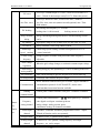
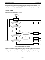
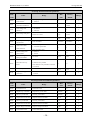
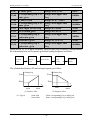
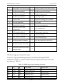
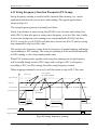
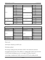
1
GK3000 User Manual Capacity: 0.4 - 400kW GK3000 series Variable Frequency Drive (VFD) adopts speed sensorless vector control technology to offer excellent control performance, enhances operation reliability and environment adaptability. Before using GK3000 VFD, please follow the instruction of this user manual. Shenzhen Gozuk Co., Limited Motor Control & Drives Manufacturer Website: www.gozuk.com Shenzhen Gozuk Co., Limited www.gozuk.com — Contents — Chapter 1 Introduction 1.1 Unpacking Inspection --------------------------------------------------------- (4) 1.2 Safety Rules -------------------------------------------------------------------- (4) 1.3 Notes on Usage ---------------------------------------------------------------- (7) 1.4 Notes Regarding Disposal---------------------------------------------------- (9) Chapter 2 Models and Specifications 2.1 Models ------------------------------------------------------------------------- (10) 2.2 Specifications ----------------------------------------------------------------- (11) 2.3 Parts of VFD ------------------------------------------------------------------ (14) 2.4 Dimensions ------------------------------------------------------------------- (14) 2.5 Optional Parts ---------------------------------------------------------------- (16) Chapter 3 Installation and Wire Connection 3.1 Installation -------------------------------------------------------------------- (18) 3.2 Removing and Mounting Front Cover of VFD -------------------------- (19) 3.3 Wire Connection ------------------------------------------------------------- (19) 3.4 Main Circuit Wiring --------------------------------------------------------- (20) 3.5 Basic Wiring Diagram ------------------------------------------------------ (22) 3.6 Control Circuit Terminal Wiring ------------------------------------------- (23) 3.7 EMC Installation Instruction ----------------------------------------------- (29) Chapter 4 Running of VFD 4.1 Running of VFD ------------------------------------------------------------- (32) 4.2 Operation and Using of the Control Panel -------------------------------- (35) 4.3 VFD power ------------------------------------------------------------------- (44) Chapter 5 Function Parameter Table 5.1 Symbol Description ---------------------------------------------------------- (45) 5.2 Function Code Table --------------------------------------------------------- (45) -2- Shenzhen Gozuk Co., Limited www.gozuk.com Chapter 6 Function Code Description 6.1 Basic running function parameter (P0 Group) --------------------------- (62) 6.2 Frequency Setting Function Parameter (P1 Group) --------------------- (69) 6.3 Start/Brake Function Parameter (P2 Group) ----------------------------- (71) 6.4 Auxiliary Running Parameter (P3 Group) -------------------------------- (74) 6.5 Terminal Control Function Parameter (P4 Group) ---------------------- (82) 6.6 Protection Function Parameter (P5 Group) ------------------------------ (97) 6.7 Fault Record Function Parameter (P6 Group) -------------------------- (100) 6.8 Close Loop Running Control Function Parameter (P7 Group) ------ (101) 6.9 Injection Machine Parameter (P7-Z Group) ---------------------------- (108) 6.10 PLC Running Parameter (P8 Group) ----------------------------------- (112) 6.11 Swing Frequency Function Parameter (P9 Group) ------------------- (117) 6.12 Vector Control Parameter (PA Group) --------------------------------- (120) 6.13 Factory Function Parameter (PF Group) ------------------------------- (121) Chapter 7 Troubleshooting 7.1 Fault Alarm and Troubleshooting ---------------------------------------- (122) 7.2 Fault Record Search -------------------------------------------------------- (125) 7.3 Fault Reset ------------------------------------------------------------------- (125) Chapter 8 Preservation and Maintenance 8.1 Preservation and Maintenance -------------------------------------------- (126) 8.2 Periodic Preservation and Maintenance --------------------------------- (126) 8.3 Warranty of VFD ----------------------------------------------------------- (127) Chapter 9 Serial Port Communication Protocol of RS485 9.1 Communication Overview ------------------------------------------------ (128) 9.2 Communication Protocol Specification --------------------------------- (128) 9.3 The ASCII Communication Protocol ------------------------------------ (130) -3- Shenzhen Gozuk Co., Limited www.gozuk.com Chapter 1 Introduction 1.1 Unpacking Inspection Upon unpacking, please confirm the following: Any damage occurred during transportation; Check whether the model and specifications on the nameplate of VFD are in accordance with your order. If there is any error, please contact us or distributors. VFD Model Description GK3000 - 4 T 0015 X GK VFD Voltage level Code 220V 2 380V 4 Input voltage Code VFD type G Constant torque P Fan pump type Code Motor Power 0007 0. 75KW 0015 1. 5KW 0075 7. 5KW Code Single phase S Three phase T Fig. 1-1 VFD model description The model and specifications on the name plate of VFD on the bottom right of VFD. 1.2 Safety Rules Inspection Inspection 1. Please do not install the damaged VFD, otherwise there is a danger of injury. -4- Shenzhen Gozuk Co., Limited www.gozuk.com Installation Inspection 1. Handling, please hold the bottom of the body, otherwise there is a danger of a body falling foot injury. 2. Please install the VFD on metal or other nonflammable material, otherwise there is a danger of fire. 3. Please install cooling fans when two VFDs are installed in a same cabinet, keep the air intake temperature under 40℃, otherwise, there is a danger of fire. Cable connection and distribution Danger 1. Wire-connection job can only be done when the mains are cut off, otherwise, there is a danger of shock or fire. 2. Only qualified personnel can perform wire-connection job, otherwise, there is a danger of shock or fire. 3. The earth terminal of VFD must be connected to earth reliably, otherwise, there is a danger of shock or fire. (Please use the 3rd grounding method specially for 380V) 4. After connects emergency stop terminal, please make sure it is effective, otherwise, there is a danger of injury. (The user is responsible for the connection) 5. Please don't touch the output terminals, don't connect the output terminals with the shell, don't short connect the output terminals, otherwise, there is a danger of shock or short circuit. -5- Shenzhen Gozuk Co., Limited www.gozuk.com Attention 1. Please confirm the mains supply is in accordance with rated voltage of VFD, otherwise, there is a danger of injury or fire. 2. Please don't make voltage withstanding test to the VFD. It may damage the semiconductor and other components. 3. Please connect the braking unit or resistance according to the wiring diagram; otherwise, there is a danger of fire. 4. Please use screw drivers with appointed moment of force to tighten the terminals, otherwise, there is a danger of fire. 5. Please don't connect input mains cable with output terminals of U/V/W. It may damage the VFD. 6. Please don't connect shifting capacitor or LC/RC noise filter with output loop. It may damage the VFD. 7. Please don't connect solenoid switch or solenoid contactor with output loop. When VFD is running with load, the action of such switch and contactor will cause surge current. It may trigger over current protection of VFD. 8. Please just disassemble the terminals cover when wiring, don't disassemble the front cover of VFD. It may damage the VFD. -6- Shenzhen Gozuk Co., Limited www.gozuk.com Maintenance and inspection Danger 1. Please do not touch the control terminals when it is live, otherwise there is a danger of shock. 2. Please make sure the terminals cover is assembled before power up. Before disassembling the terminals cover, please make sure the power is cut off, otherwise, there is a danger of shock. 3. Only qualified personnel can perform the maintenance and inspection job, otherwise, there is a danger of shock. Attention 1. The keyboard, control circuit board, and driver circuit board were integrated with CMOS circuit. Please be careful when using. Please do not touch these circuit boards by fingers. 2. Please don't change the cable connection when power on. 1.3 Notes on Usage In the use of GK3000 series VFD, please pay attention to the following points: 1. Constant torque low speed running When the VFD outputs to a common motor at low speed for a long term, the output rated torque should be derated due to the worsening radiating effect. If low speed constant torque long term running is required, then a special variable frequency motor is needed. -7- Shenzhen Gozuk Co., Limited www.gozuk.com 2. Confirm motor's insulation Before using GK3000 series VFD, please confirm the motor is insulated; otherwise, the equipment may be damaged. Please confirm motor's insulation termly when motor is working under bad condition. 3. Negative torque load To some application situation such as lifting load, negative torque load may occur. Braking unit and resistor should be connected with VFD, or over current or over voltage fault may happen. 4. The mechanical resonance point of load The VFD may encounter the mechanical resonance point of load within certain output frequency range. Jump frequencies have to be set to avoid it. 5. Capacitor and varistor Because the VFD outputs PWM pulse wave, capacitor and varistor should not be connected with the output terminals of the VFD, or the VFD may trip or components may be damaged, as shown in Fig. 1-3. Fig. 1-3 Capacitor connection with VFD output prohibited 6. Motor derating When basic frequency is set to be lower than rated frequency, motor derating is necessary in order to avoid motor overheating. 7. Running at frequency above 50Hz If running at frequency above 50Hz, besides the increment of vibration and noise, the ranges of running speed of motor shaft and mechanical device have to be -8- Shenzhen Gozuk Co., Limited www.gozuk.com guaranteed. Be sure to make an enquiry first. 8. The electro-thermal protective value of motor If the applicable motor is selected as per requirements, the VFD can perform the thermal protection to the motor. If the ratings of applied motor are not in compliance with the VFD, be sure to adjust the protective value to guarantee the safe running of motor. 9. Altitude and derating When the altitude is higher than 1000m, the cooling effect of VFD is deteriorated because of the rareness of air, derating must be considered. Iout 100% 90% 80% 1000 2000 3000 4000 ( 米) (m) Fig. 1-4 indicates the relationship between the altitude and rated current of VFD. 10. On the level of protection GK3000 VFD protection grade IP20 could be reach when the selection of state display unit or the keyboard. 1.4 Notes Regarding Disposal When you dispose VFD, pay attention to: The capacitors in the main circuits may explode when they are burned. Poisonous gas may be generated when front panel is burned. Please dispose the VFD as industrial rubbish. -9- Shenzhen Gozuk Co., Limited www.gozuk.com Chapter 2 Models and Specifications 2.1 Models GK3000 series VFD has 2 kinds of voltage levels, 220V and 380V. The range of applicable motor is from 0.4KW to 450KW. Models of GK3000 series are shown in Table 2-1. Table 2-1. Models description Voltage level Models Light duty Capacity (KVA) Rated Applicable current(A) motor(KW) GK3000-2S0004G 1.1 3.0 0.4 220V GK3000-2S0007G 1.5 4.7 0.75 Single phase GK3000-2S0015G 2.8 7.5 1.5 GK3000-2S0022G 3.8 10.0 2.2 220V GK3000-2T0015G 3.0 7.0 1.5 Three phase GK3000-2T0022G 4.0 10.0 2.2 GK3000-4T0007G 1.5 2.5 0.75 GK3000-4T0015G 2.5 4.0 1.5 GK3000-4T0022G GK3000-4T0022P 3.0 6.0 2.2 GK3000-4T0037G GK3000-4T0037P 5.9 9.6 3.7 GK3000-4T0055G GK3000-4T0055P 8.5 14.0 5.5 GK3000-4T0075G GK3000-4T0075P 11 17.0 7.5 GK3000-4T0110G GK3000-4T0110P 17 25 11 380V GK3000-4T0150G GK3000-4T0150P 21.7 32 15 Three phase GK3000-4T0185G GK3000-4T0185P 25.7 39 18.5 GK3000-4T0220G GK3000-4T0220P 29.6 45 22 GK3000-4T0300G GK3000-4T0300P 39.5 60 30 GK3000-4T0370G GK3000-4T0370P 49.4 75 37 GK3000-4T0450G GK3000-4T0450P 60 91 45 GK3000-4T0550G GK3000-4T0550P 73.7 112 55 GK3000-4T0750G GK3000-4T0750P 99 150 75 GK3000-4T0900G GK3000-4T0900P 116 176 90 - 10 - Shenzhen Gozuk Co., Limited 380V Three phase www.gozuk.com GK3000-4T1100G GK3000-4T1100P 138 210 110 GK3000-4T1320G GK3000-4T1320P 167 253 132 GK3000-4T1600G GK3000-4T1600P 200 304 160 GK3000-4T1850G GK3000-4T1850P 234 355 187 GK3000-4T2000G GK3000-4T2000P 248 377 200 GK3000-4T2200G GK3000-4T2200P 280 426 220 GK3000-4T2500G GK3000-4T2500P 318 474 250 GK3000-4T2800G GK3000-4T2800P 342 520 280 GK3000-4T3150G GK3000-4T3150P 390 600 315 GK3000-4T3500G GK3000-4T3500P 435 660 350 GK3000-4T4000G GK3000-4T4000P 493 750 400 GK3000-4T4500G GK3000-4T4500P 560 850 450 2.2 Specifications Items Voltage/Freq. Specifications Single phase220V, three phase 200V, three phase 380V;50Hz/60Hz Input Range Rated voltage Output Freq. range Freq. resolution Overload ability Modulation Voltage: ±20% voltage unbalance rate: <3%; frequency: ±25% 0~200V/220V/380V 0Hz~500Hz 0.01Hz 150% rated current for 1 minute, 180% rated current for3 seconds Optimized space voltage vector SVPWM modulation modes Control mode Sensorless vector control (with optimal low frequency, dead time compensation) Frequency Digital setting: The highest frequency×± 0.01% Analog setting: The precision highest frequency ±0.2% Frequency Digital setting: 0.01Hz; Analog setting: The highest frequency× Control resolution 0.1% function Start frequency 0.40Hz~20.00Hz Torque boost Auto torque boost, manual torque boost 0.1%~30.0% - 11 - Shenzhen Gozuk Co., Limited V/F curve www.gozuk.com Five ways: constant torque V/F curve, 1 kind of user defined V/F curve , 3 kinds of down torque curve(2.0/1.7/1.2times the power) Two ways: linear Acc./Dec., S-curve Acc./Dec.;7 kinds of Acc./Dec. curve Acc./Dec. time, time unit (minute/second) optional, max. Time: 6000 minutes. DC braking start frequency: 0~15.00Hz DC braking Energy consuming braking Jog running PI built-in Multi-stage speed running Textile swing frequency Auto voltage regulation Auto energy braking time: 0~60.0seconds braking current: 0~80% Energy consuming braking unit built-in, external braking resistor can be Jog frequency range: 0.1Hz~50.00Hz, JOG Acc./Dec. time: 0.1~60.0s Easily constitute a close loop control system Multi-stage speed running available through built-in PLC or control terminals Swing frequency available with preset and center frequency adjustable When the grid voltage changes, to maintain constant output voltage Saving energy by auto optimizing V/F curve according to the load saving running Auto current limiting Auto current limiting to prevent frequent over current fault trip Fixed-length control VFD stops when reaches the preset length RS485 standard communication port available, support MODBUS Communication communication protocol of ASCII and RTU, master-slave multi-machine interaction function available Running Control panel: control terminal: serial port: 3 channels switchable command channel Control panel potentiometer : ▲, ▼control panel keys: ;function Frequency Runni setting channel ng functi on code digital: serial port : terminal up/down: analog voltage: analog current: pulse: combination setting: all channels switchable Switch input FWD/REV command: 8channels programmable switch channel 35kinds of function can be set separately Analog input channel 4~20mA: 0-10V: 2 optional analog inputs Analog output 4~20mA or 0~10V optional, setting frequency and output channel frequency , etc. can be output - 12 - inputs, Shenzhen Gozuk Co., Limited Switch/pulse Contro l panel www.gozuk.com Programmable open collector output: relay output : 0~20KHz pulse output channel output. LED digital display Display setting frequency, output voltage, output current, etc. External meter display Display output frequency, output current, output voltage, etc. Key lock Parameter copy Protection function Optional parts Environment Enviro Altitude nment Ambient temperature All the keys can be locked Function code parameters are able to be copied between VFDs when use remote control panel. Over current protection: over voltage protection: under voltage protection: overheating protection: over load protection, etc. Braking unit: remote control panel: cable: panel mounting feet, etc. Indoors, free from direct sunlight, dust, corrosive gas, oil mist, steam, water dropper salt, etc. Lower than 1000m (derating is necessary above 1000m) -10℃~+40℃ Humidity <90%RH, no condensation Vibration Lower than 5.9m/s (0.6g) Storage temperature -20℃~+60℃ Struct Protection level IP20 (In the selection of state display unit or the keyboard state) ure Cooling Installation Forced air cooling Wall mounted - 13 - Shenzhen Gozuk Co., Limited www.gozuk.com 2.3 Parts of VFD H H1 H2 H H1 H2 D2 D 1 D2 D D1 2.4 Dimensions W1 W W1 W d (a), VFDs below 2.2 KW d (b), VFDs from 3.7 KW to 160 KW - 14 - Shenzhen Gozuk Co., Limited www.gozuk.com Table 2-2 Dimensions (mm) Type Number W W1 H H1 H2 D D1 D2 d 85 70 155 144 142 121.7 112 70 5 98 88 180 174 168 135 146 80 5 118 108 230 220 210 153 164 100 5 216 202 300 290 300 212 217 110 6 245 186 350 334 310 215 220 130 10 291 200 520 500 477 266 280 170 10 348 300 587 563 544 293 308 170 10 395 278 618 598 578 300 310 250 10 482 282 652 632 612 310 320 260 10 GK3000-2S0004 GK3000-2S0007 GK3000-2S0015 GK3000-4T0007 GK3000-4T0015 GK3000-2S0022 GK3000-4T0022 GK3000-4T0037 GK3000-4T0055 GK3000-4T0075 GK3000-4T0110 GK3000-4T0150 GK3000-4T0185 GK3000-4T0220 GK3000-4T0300 GK3000-4T0370 GK3000-4T0450 GK3000-4T0550 GK3000-4T0750 GK3000-4T0900 GK3000-4T1100 GK3000-4T1320 GK3000-4T1600 GK3000-4T1850 GK3000-4T2200 600 1440 400 GK3000-4T2500 - 15 - Shenzhen Gozuk Co., Limited www.gozuk.com 2.5 Optional Parts: The following options, if necessary, please to my company ordered another. 2.5.1 Remote control RS 485 communication applied between remote control panel and VFD which are connected by a 4-core cable via RJ45 network port. The maximum connection distance is 500 M. The VFD supports local control panel and remote control panel used at the same time, no priority, both can control the VFD. Hot Plug In for remote control panel is available. The following functions are available by using remote control panel: (1) Control slave VFD to run, stop, jog run, fault reset, change setting frequency, change function parameters and running direction. (2) Monitor slave VFD's running frequency, setting frequency , output voltage, output current, busbar voltage, etc. 2.5.2 Communication cable for remote control panel Type: GK3000-LAN0020 (2.0m) Standard options: 1m, 2m, 5m, 10m, 20m, More than 20m can be customized. For the remote keyboard and VFD host connection 2.5.3 Field bus Adapter The VFD can be connected into MODBUS field bus network via adapter as a slave station in the network. The function as follow: (1) To send command to VFD such as start, stop, jog running, etc. (2) To send speed or frequency signal to VFD. (3) To read status from VFD. (4) To fault reset for the VFD. Please refer to Chapter 9 for communication protocol - 16 - Shenzhen Gozuk Co., Limited www.gozuk.com 2.5.4 Braking Resistors GK3000 series VFDs under15KW have built-in braking units. If energy consuming braking is required. Please choose braking resistors according to Table 2-3. The wire connection of braking resistors is shown in Fig. 2-2. Fig.2-2 the wire connection of braking resistors Table 2-3 Braking resistors selection table Model Motor capacity (KW) Resistance (Ω ) Resistance power (W) GK3000-2S0004G 0.4 200 100 GK3000-2S0007G 0.75 150 200 GK3000-2S0015G 1.5 100 400 GK3000-2S0022G 2.2 70 500 GK3000-4T0007G 0.75 300 400 GK3000-4T0015G 1.5 300 400 GK3000-4T0022G 2.2 200 500 GK3000-4T0037G 4.0 200 500 GK3000-4T0055G 5.5 30 1000 GK3000-4T0075G 7.5 30 1000 - 17 - Shenzhen Gozuk Co., Limited www.gozuk.com Chapter 3 Installation and Wire Connection 3.1 Installation 3.1.1 Environment Requirements (1) Please mount inside a well-ventilated location. The ambient temperature is required to be within the range of -10 ~40 ℃. If the temperature is higher than 40℃, the VFD should be derated, at the same time the ventilation and heat dissipation should be enhanced. (2) Be away from the location full of dust or metal powder, and mount in the location free of direct sunlight. (3) Mount in the location free of corrosive gas or combustible gas. (4) Humidity should be lower than 90% with no dew condensation. (5) Mount in the location where vibration is less than 5.9 m/s2 (0.6G). (6) Please try to keep the VFD away from EMI source and other electronic devices which are sensitive to EMI. 3.1.2 Mounting Space and Direction (1) Generally in vertical way. (2) For the requirements on mounting space and distance, refer to Fig. 3-1. (3) When several VFDs are installed in one cabinet, they should be mounted in parallel with special incoming and out coming ventilation and special fans. When two VFDs are mounted up and down, an air flow diverting plate should be fixed as shown in Fig. 3-2 to ensure good heat dissipation. - 18 - Shenzhen Gozuk Co., Limited www.gozuk.com VFD Air flow diverting plate VFD Fig. 3-1 Mounting space and distance Fig. 3-2 Mounting of multiple VFDs 3.2 Removing and Mounting Front Cover of VFD Removing: remove 4 screws on the cover and take the cover out. Mounting: Align the mounting holes and screw them. 3.3 Wire Connection Attention (1) Before wiring, please ensure the power has been removed and be waited for at least 10minutes. (2) Please do not connect AC power to output terminals U/V/W. (3) To ensure the safety, the VFD and motor should be safety grounding. It is necessary to use copper wire above 3. 5mm as ground wire, grounding resistance less than 10Ω. (4) The VFD has gone through voltage withstand test in factory, please do not make it again. (5) Solenoid switch or absorbing devices, such as ICEL, is prohibited to connect VFD output. (6) To provide input over current protection and for convenience in - 19 - Shenzhen Gozuk Co., Limited www.gozuk.com maintenance, the VFD should be connected to AC power through circuit breaker. (7) Please use twisted wire or shielded wire above 0. 75mm for the wiring of relay input/output loop (X1~X6, FWD, REV, OC, DO). One end of shielding layer suspended, and the other side connected to PE grounding terminal of VFD, wiring length less than 50m. Danger (1) The cover can be removed only when the power is switched off, all the LEDs on the panel are off and waiting at least for 10 minutes. (2) Wiring work can be performed only when the DC voltage between P+ and P- terminals is lower than 36V. (3) Wiring work can only be done by trained or professional personnel. (4) Before usage, check whether the mains voltage meets the requirement of VFD input voltage. 3.4 Main Circuit Wiring GK3000 Circuit breaker AC power R (R) S T (T) U V W PE Fig. 3-3 Main circuit wiring - 20 - M Shenzhen Gozuk Co., Limited www.gozuk.com 3.4.1 Main Circuit Wiring Main Circuit input/output terminals, shown as Table 3-1 Table 3-1 Description of Main Circuit input/output terminals Apply to Terminal Main circuit terminal 220V 1-phase 0.4KW~2.2KW L1 L2 E U V W 380V 3-phase 0.75KW~2.2KW S R T PB P+ U V W 380V 3-phase 2.2KW~5.5KW P+ PB R S T U V W E 380V 3-phase 7.5KW~15KW T P+ P- PB U V W E R S 380V 3-phase 18.5KW~450KW R S function name T P+ P- U V W E - 21 - L1, L2 220V 1-phase Input terminals U, V, W 380V 3-phase Output terminals E Wiring terminals R, S, T 380V 3-phase Input terminals U, V, W 380V 3-phase Output terminals P+, PB Braking resistor wiring terminals R, S, T 380V 3-phase Input terminals U, V, W 380V 3-phase Output terminals P+, PB Braking resistor wiring terminals R, S, T 380V 3-phase Input terminals U, V, W 380V 3-phase Output terminals P+, PB Braking resistor wiring terminals R, S, T 380V 3-phase Input terminals U, V, W 380V 3-phase Output terminals P+, P- Braking resistor wiring terminals Shenzhen Gozuk Co., Limited www.gozuk.com 3.5 Basic Wiring Diagram MCCB Three phase Motor U R S V T W GK VFD M E X1 Grounding X2 P+ X3 Braking resistor PB X4 Ta X5 Tb X6 Fault relay output Tc FWD DC current meter REV AO COM GND +10V DO 0~10V 0~10V/4~20mA VI OC High speed pulse output Open collector output CI 485+ GND 485- Fig. 3-5 Basic wiring diagram - 22 - Standard RS485 communication Shenzhen Gozuk Co., Limited www.gozuk.com 3.6 Control Circuit Terminal Wiring 3.6.1 Position and Function of Terminals and Jumpers on Control Circuit JP1 JP4 JP3JP2 CN2 RS485 CN1 Fig. 3-6 Position of terminals and jumpers on control circuit Before using the VFD, Please make correct terminals wiring and jumpers setting. It is suggested to use above 1mm2 wire as terminal connection wire. Table 3-2 Jumper switch function NO JP1 JP2 JP3 JP4 Function Setting Setting FD Pulse output terminal 1-2 connected: internal24V power of VFD external DO power selection 2-3 connected: external power power Analog output terminal AO 1-2: 0~10V: AO1 output voltage signal current/voltage output selection 2-3: 4~20mA: AO1 output current signal Terminal CI current/voltage 1-2 : V side, 0~10 voltage signal Input selection 2-3 : I side, 4~20 mA current signal X7 terminal input mode 1-2 : PLC side, X7 used as multifunctional terminal selection 2-3 : FCH side: X7 used as an external pulse input - 23 - 0~10V 0~10V PLC side Shenzhen Gozuk Co., Limited www.gozuk.com 3.6.2 Description of Terminals on Control Circuit (1) Function of CN 1 terminal shown as Table 3-3 Table 3-3 CN 1 terminal function Sort Relay output terminal Terminal Name Function Description TA/RA Can be defined as multifunctional TA-TC: NC, TA-TB: Normally open contact TB/RB TC/RC Multifunctional relay output terminal Specification Relay output terminal by capacityAC250V/2A (COSΦ=1) programming, refer to Chapter AC250V/1A (COSΦ=0. 4) 6.5 P4.12, P4.13 DC30V/1A (2) Control Circuit CN2 terminal shown as Fig. 3-7 485+ P24 X1 X3 485- COM X2 X5 FWD REV DO AO1 AO2 VI 10V X4 X6 COM OC1 OC2 GND CI GND PE Fig. 3-7 CN2 terminals (3) Function of CN 2 terminal shown as Table 3-4 Table 3-4 CN 2 terminal function Sort Communic ation Terminal 485+ 485- Pulse Output terminal Multifuntioal output terminal OC1 OC2 DO Name Function Description RS485 differential signal positive terminal RS485 differential signal negative terminal Can be defined as multifunctional Open collector on-off output terminal by output terminal 1 programming, refer to Chapter 6. 5P4. 10 (Common port: COM) Can be defined as multifunctional Open collector on-off output terminal by output terminal 2 programming, refer to Chapter 6. 5P4. 11 (Common port: COM) RS485 communication port Open collector pulse Output terminal Can be defined as multifunctional Pulse output terminal by programming, Refer to Chapter 6. 5P4. 21/P4. 22 (Common port: COM) - 24 - Specification Twisted or shielded wire needed Opto isolated output Working voltage: 9~30V Max. output current: 50mA Opto isolated output Working voltage: 9~30V Max. output current: 50mA Max. output frequency: 20KHz Output freq range defined by P4. 21 Shenzhen Gozuk Co., Limited Analog input VI CI Analog output AO1 Running control terminal Multifunctional input terminal Analog voltage input (Grounding: GND) Analog voltage/current input, Choose voltage or current input by Analog input CI Setting JP3 jumper. Factory default: voltage input (Grounding: GND) Analog voltage/current output, indicating 7quantities, choose voltage Analog output or current output by setting JP2 jumper. AO1 Factory default: voltage output (Grounding: GND) AO2 Analog output AO2 FWD Forward running REV Reverse running Analog voltage output, indicating 7quantities(Grounding: GND) Input voltage range: 0~10V (input resistance: 47KΩ) Resolution: 1/1000 Input voltage range: 0~10V (input resistance: 47KΩ) Input current range: 0~20mA (input resistance: 500Ω) Resolution: 1/1000 Current output range: 4~20mA Voltage output range: 0~10V Voltage output range: 0~10V Refer to chapter 6. 5 P4. 08 X1 X2 X3 X4 X5 X6 P24 10V Power source Analog input VI www.gozuk.com GND COM Multifunctional input terminal 1 Multifunctional input terminal 2 Multifunctional input terminal 3 Multifunctional input terminal 4 Multifunctional input terminal 5 Multifunctional input terminal 6 +24Vpower source +10Vpower source +10Vcommon port +24Vcommon port Opto isolated input Input resistance: 2KΩ Can be defined as multifunctional Max. input frequency: 200Hz on-off input terminal by programming, Input voltage range: 9~30V refer to Chapter 6.5 P4. (Common port:COM) Supply +24V power (negative terminal: COM) Supply+10Vpower(negative terminal: Max. Output current: 50mA GND) Grounding of analog signal and+10V power source Terminal COM and GND are Isolated inside Digital signal input, output common port - 25 - Shenzhen Gozuk Co., Limited www.gozuk.com 3.6.3 Analog Input/Output Terminal Wiring (1) Analog voltage signal input through VI terminal as follow wiring: GK3000 10V + VI ― 0~+10V GND Shielded cable PE Fig. 3-7 VI terminal wiring (2) Analog signal input through CI terminal, jumper selection for input voltage (0~10V) or input current (4~20mA) as follow wiring 10V CI current V CI I CI JP3 GK3000 + 0~+10V Or 4~20mA ― GND PE Shielded cable CI voltage I C V JP3 Fig. 3-8 CI terminal wiring (3) Analog output terminal AO wiring Analog output terminal can be connected with external analog meter indicating various physical quantity, jumper selection for output voltage (0~10V) or output current (4~20mA) as follow wiring. Analog meter Analog voltage output I AO1 V AO1 VFD JP2 GND Analog current output I AO1 V Fig. 3-9 Analog output terminal wiring - 26 - Shenzhen Gozuk Co., Limited www.gozuk.com Notes: (1) Filter capacitor or common-mode inductor can be installed between VI and GND terminal or CI and GND terminal when using analog input mode. (2) Please use shielded cable and do well grounding, keep the wire as short as possible in order to prevent external interference when using analog input/output mode. 3.6.4 Communication Terminal Wiring The VFD supplies standard RS 485 communication port. It can constitute a single host-single slave control system or a single host-multi slaves system. The upper computer (PC/PLC) can real time monitor the VFD in the control system and achieve complicated control function such as remote control and supermatic, etc. (1) Remote control panel can be connected with VFD via RS485 port by plugging in the remote control panel into RS485 port without any parameter setting. The local control panel of VFD and remote control panel can work at the same time. (2) VFD RS485 port and upper computer wiring as follow: GK3000 Fig. 3-10 RS485-(RS485/232)-RS232 communication wiring - 27 - Shenzhen Gozuk Co., Limited www.gozuk.com (3) Multi VFDs can be connected together via RS485, controlled by PC/PLC as a host shown as Fig. 3-12. It also can be controlled by one of VFDs as a host shown as Fig. 3-13. PLC +485- PE GK3000 GK3000 GK3000 GK3000 +485- PE +485- PE +485- PE +485- PE Fig. 3-12 PLC communication with multi VFDs GK3000 +485- PE GK3000 GK3000 GK3000 GK3000 +485- PE +485- PE +485- PE +485- PE Fig. 3-13 Multi VFDs communication The more VFDs connected, the more serious the communication interference becomes. Please make wiring as above and do well grounding for VFDs and motors, or adopt the following measures to prevent interference as even above wiring can't work. (1) Separately power supply to PC/PLC or isolated the power of PC/PLC. (2) Use EMIFIL to the wire or reduce carrier frequency properly. - 28 - Shenzhen Gozuk Co., Limited www.gozuk.com 3.7 EMC Installation Instruction VFD outputs PWM wave, it will produce electromagnetic noise. To reduce the interference, EMC installation will be introduced in this section from noise suppression, wire connection, grounding, leakage current and filter of power supply 3.7.1 Noise Suppression (1) Noise Type Noise is unavoidable during VFD operation. Its influence over peripheral equipment is related to the noise type, transmission means, as well as the design, installation, wiring and grounding of the driving system. - 29 - Shenzhen Gozuk Co., Limited www.gozuk.com (2) Noise Suppression Methods Table2-5 Noise suppression method Path Noise suppression methods If a closed loop if formed between the peripheral equipment and the VFD wiring, the ② grounding leakage of the VFD will misoperate the equipment. Solution: Remove the grounding of the peripheral equipment When peripheral equipment share the same power source with the VFD, the noise ③ transmitted through the power line may misoperate the peripheral equipment. Solution: Mount a noise filter at VFD input side, or isolate the peripheral equipment with an isolated transformer or power filter. Electronic equipment such as computers, measuring meters, sensors and radio equipment, when in the same cabinet with VFD, with their wiring close to the VFD, may misoperate due to radio interference. Solution: 1) The susceptible equipment and its signal lines should be kept away from the VFD. Use shielded cable for the signal line. Ground the shielding coat. Protect the signal cable with a metal pipe and keep it off the VFD input/output cable. When crossing of the ④⑤⑥ signal line and the VFD input/output cables is inevitable, make sure it’s orthogonal. 2) Mount radio noise filter or linear noise filter (choke coil) to the input/output side of the VFD to suppress the radio noise. 3) The shielding coat for the cable connecting VFD and the motor should be thick. The wiring can be arranged through thick pipe (2mm or thicker) or cement trench. The cable should be through a metal pipe, and has its shielding coat grounded. You may use the 4-core cable as the motor power cable. Ground one core at VFD side, with the other end of it connected to the motor case. When the signal cables are parallel to, or bound together with the power cables, the static and electromagnetic induction will cause the noise transmit through the signal cable, misoperating the related equipment. Solution: 1) Avoid laying the signal cable parallel to the power cable, or bind them ①⑦⑧ together. 2) Keep the susceptible peripheral equipment away from the VFD. 3) Keep the susceptible signal bables away from the input/output cables of VFD. Shielded cables should be used as the signal or power cable. Lead them through metal pipes respectively would achieve better effect. The metal pipes should be at least 20 cm away from each other. - 30 - Shenzhen Gozuk Co., Limited www.gozuk.com 3.7.2 Wiring Connection and Grounding (1) Please try not to wire motor cable (from VFD Power cable/Motor cable to motor) in parallel with power cable and keep at least 30cm from each other . (2) Please try to arrange the motor cable through metal pipe or in-metal wiring groove. Control signal cable Fig. 3-16 Orthogonal wiring (3) Please use shielded cable as control signal cable, and connect the shielding coat to PE terminal of VFD with proximal grounding to VFD. (4) PE grounding cable should be directly connected to the earth plate. (5) The control signal cable should not be in parallel with strong electricity cable (power cable/motor cable). They should not be bent together and should be kept away as least 20cm from each other. If cable crossing is inevitable, please make sure it is orthogonal as Fig. 3-1 6 (6) Please ground the control signal cable separately with power cable/motor cable. (7) Please don't connect other devices to VFD power input terminals(R/S/T). - 31 - Shenzhen Gozuk Co., Limited www.gozuk.com Chapter 4 Running of VFD 4.1 Running of VFD 4.1.1 Running Command Channels There are three channels for VFD receiving commands like START, STOP, JOG and others. Control panel Use RUN default) STOP RESET JOG Keys on the panel to control the VFD. (Factory Control terminal Use terminal FWD, REV, COM to constitute a 2-wire control mode, or use one of terminals amongX1~X6 and FWD, REV to constitute a 3-wire control mode. Serial port Use upper computer (PC/PLC) or host VFD to control slave VFD to start or stop via serial port. The command channels can be selected by setting Function Code P0.03, or by multifunctional input terminal (function code P4.00-P4.07). Note: These three channels are all switchable. Please make debugging before switch so as to avoid equipment damage and personal injury. 4.1.2 Frequency setting channel There are 8 kinds of frequency setting channels as follow: 0: by control panel potentiometer 1: by ▲ ▼ control panel keys 2: digital setting by function code via control panel 3: via terminal UP/DOWN 4: by upper computer via serial port 5: analog setting via VI terminal - 32 - Shenzhen Gozuk Co., Limited www.gozuk.com 6: analog setting via CI terminal 7: via pulse terminal 8: combination setting 4.1.3 VFD Running States There are two VFD running states which are stopping state and running state. Stopping state: The VFD is in stopping state before running control command is accepted after the power is on or deceleration to stop. Running state: After running control command is accepted, the VFD enters running state. 4.1.4 The Running Modes of VFD There are five running modes according to priority which are JOG running, close loop running, PLC running, multi-stage speed running, normal running as shown in Fig.4-1. 0: JOG running In stopping state, after receiving JOG running command, the VFD will run according to JOG frequency, for example, by pressing control panel JOG give JOG command (refer to function code P3.06~P3.08). key to 1: Close loop running By setting close loop running control parameter effective (P7.00=1), the VFD will enter close loop running, that is PI regulation (refer to function code P7). To make close loop running invalid, please set multifunctional input terminal (function27) and switch to lower level running mode. 2: PLC running By setting PLC function parameter effective (P8.00 units 0), the VFD will enter PLC running mode and go to run according to preset running mode (refer to function code P8). To make PLC running invalid, please set multifunctional input terminal (function29) and switch to lower level running mode. 3: Multi-stages peed running - 33 - Shenzhen Gozuk Co., Limited www.gozuk.com By setting non-zero combination of multifunctional input terminal (function1, 2, 3) and selecting multi-frequency 1-7, the VFD will enter multi-stage speed running mode(refer to function codeP3.26~P3.32). 4: Normal running Simple open loop running mode of VFD. Power on High priority level Stopping state JOG running YES Is there a JOG command NO NO s running command effective YES Is close loop effective NO YES YES Is PLC effective? terminal closed and close loop invalid NO Close loop running YES Is terminal closed and PLC invalid? YES NO NO PLC running YES Low priority level Multi-stage speed running Are multi-stage freq. Terminal valid? NO Normal running Fig.4-1 Running mode logic diagram The above 5 kinds of running modes can be running in multiple frequency setting channel except JOG running. PLC running, multi-stage speed running and normal running can carry out swing frequency conditioning. - 34 - Shenzhen Gozuk Co., Limited www.gozuk.com 4.2 Operation and Using of the Control Panel 4.2.1 Control Panel Layout User can perform VFDs' start, speed modulation, stop, braking, setup the running parameters and control peripheral equipment through control panel and control terminal 电流(A ) 数码显示 Digitals Current unit 频率(H z)(Hz) Freq. unit LEDLCD display Voltage) unit (V) 电压(V Analog模式指示灯 indicator 变频器逆相输出指示灯 Reverse output indicator Alarm 警告指示灯 Forward output indicator 变频器正相输出指示灯 MENU ESC Menu selection/exit key 模式切换键 Save/switch key 参数修改位数切换键 DATA Shift key 确认、存贮键 JOG/reverse 反转、点动键 停机、故障复位键 Stop/reset key Increase key 上升键 参数修改 Decrease key 下降键 CVF-KP22A 正转运行键 Forward running key Fig. 4-2 Control panel diagram 4.2.2 Control Panel Function There are 8 keys and 1 analog potentiometer on the VFD's panel. The functions are shown as follow: Keys Function Forward RUN running key Function specification Press this key to forward run. - 35 - Shenzhen Gozuk Co., Limited www.gozuk.com STOP RESET MENU ESC JOG In the panel control mode, press this key to stop VFD running, and reset Stop/reset key in fault state. Menu Enter or exit programming state selection/exit JOG/reverse In the panel control mode, press this key for JOG running or key reverse running. ▲ Increase key Increase of data or code ▼ Decrease key Decrease of data or code In the programming state, press this key to change the data's ►► Shift key ENTER Save/switch In the programming state, press this key to enter the next menu or save key the function code data. Analog In potentiometer control mode (P0.01=0), the output frequency can be potentiometer controlled by regulating this potentiometer. DATA revising bit. 4.2.3 LED Display and Indictor Description There are a 4 digits LED display, 3 unit indicators and 3 state indicators. These 3 unit indicators have 6 kinds of combinations corresponding to 6 kinds of unit indicating as Fig.4-3 Hz A Hz A S S % V No unit Hz Hz A S A V % Fig. 4-3 Indicator state and unit indicating - 36 - % V OFF ON S % V Hz A S % V V A A S % % V Hz Hz S Shenzhen Gozuk Co., Limited www.gozuk.com Table 4-2 State indicator description Item Function Description LED digital display Display VFD's running state parameters and setting parameters. When the motor is running forward, this FWD function When the VFD is in DC braking indicator is on. Display state, the FWD and REV indictor State indicator When the motor is running reverse, this REV are on at the same time. indicator is on. ALM When there is a fault alarm, this indicator is on 4.2.4 Control Panel Display State The control panel display state includes parameter displaying in stopping state, function code parameter displaying in programming state, fault displaying in alarm state, and parameter displaying in running state. A. Parameter displaying in stopping state When VFD is in stopping state, panel displays stopping state monitoring parameter which usually is set frequency (b-01 monitoring parameter) shown as Fig.4-4 B. Press ►► key to display the other monitoring parameter (The VFD default displays the first 7 monitoring parameters of b group. The other parameters can be defined by function code P3.41 and P3.42. Please refer to Chapter 5). When in parameter displaying, press ENTER key for switching to default display parameter DATA b-01, that is setting frequency, or it will always be displaying the monitoring parameter displayed last time. - 37 - Shenzhen Gozuk Co., Limited www.gozuk.com V MENU ENTER MENU ENTER MENU ENTER ESC DATA ESC DATA ESC DATA ►► FWD JOG ►► FWD JOG ►► FWD JOG ▲ ▼ STOP ▲ ▼ STOP ▲ ▼ STOP A RESET Initializing after power on B RESET Display and flashing in stopping state C RESET Display without flashing in running state Fig.4-4 Parameter display in initialization, stopping and running state. B. Parameter displaying in running state The VFD enters running state after receiving effective running command, and the panel displays running state monitoring parameter. It default displays output frequency (b-00 monitoring parameter) shown as Fig.4-4 C. Press ►► key to display the other monitoring parameter (defined by function code P3.41 and 3.42). When in parameter displaying, press ENTER key for DATA switching to default display parameter b-00, that is output frequency, or it will always be displaying the parameter displayed last time. C. Fault displaying in alarm state The VFD enters fault alarm display state after fault signal is detected. The displayed fault code will be flashing. Press ►► key to check fault related parameter. When checking fault related parameter, press ENTER DATA key for switching to fault code display. - 38 - Shenzhen Gozuk Co., Limited www.gozuk.com MENU Press ESC key to enter programming state to check P6 group parameter of fault information STOP After troubleshooting, press RESET key to reset the VFD (or via control terminal/serial port) If the fault still exists, it will keep displaying the fault code. Note: To some serious faults such as IGBT protection, over current, over voltage, etc. Don't reset the VFD before clearing the fault for sure, otherwise there is a danger of damage. MENU ENTER ESC DATA ►► FWD JOG ▲ ▼ STOP RESET Fig. 4-5 Fault alarm display state D. Function code programming state In the state of stopping, running, and fault alarm, press MENU ESC key to enter programming state (A password is required, If it has been set. Please refer to P0.00 description and Fig.4-10). The programming state includes three display menus shown as Fig.4-6 which in order is function code group function code number function code parameter. Press ENTER key to enter each menus. When in function code parameter display DATA menu, press ENTER key to save parameter, press MENU key to go back to previous ESC DATA menu without parameter saving. First menu Second menu MENU/ESC ENTER/DATA MENU/ESC MENU/ESC Third menu ENTER/DATA MENU/ESC ENTER/DATA Stopping state/running Programming state State /fault alarm state Fig. 4-6 Control panel programming state - 39 - Shenzhen Gozuk Co., Limited www.gozuk.com 4.2.5 Control Panel Operation Through the operating panel of VFD for various operations, for example as follows: A. Switching display of state monitoring parameter Press ►► key to display b group state monitoring parameter. It first displays the order of monitoring parameter, after 1 second, it switches automatically to display the value of this monitoring parameter shown as Fig.4-7. LED 50.00 b-01 1 SEC 1 SEC 1SEC Parameter b-02 Parameter b-03 Parameter Display Output freq ►► Set freq. ►► Output voltage ►► Output current Key operation Parameter ►► 1 SEC 1 SEC b-14 Module temperature Parameter b-04 Busbar voltage ►► …… ►► Fig. 4-7 Operation to display monitoring parameter ENTER (2) When viewing monitoring parameter, press DATA key for switching to default monitoring parameter display state. Default monitoring parameter is setting frequency in stopping state, and default monitoring parameter in running state is output frequency. - 40 - Shenzhen Gozuk Co., Limited .B. www.gozuk.com Function code parameter setting For example, to set parameter code P3.06 from 5.00Hz to 8.50Hz. LED 50.00 -P0- -P3- P3.00 P3.06 05.00 05.00 ENTER ▲ ENTER ►► Display MENU ESC Stop Key ▲ Enter programming Select function state first menu parameter DATA Enter second menu code group P3 Select function DATA Enter third menu Select parameter bit code P3.06 operation display -P3- P3.07 08.50 08.00 08.00 MENU MENU ENTER ESC ESC DATA ▲ ►► ▲ Go back to Save parameter Parameter revising0→5 first menu and go state Exit Select Parameter 5→8 parameter bit k Fig. 4-8 Example ofb function code parameter setting Note: In third menu, if the parameter displayed is not in flashing, it means that this function code is unable to be revised. Probably the reasons are: (1) This function code parameter is unmodifiable, such as actual detected state parameter, record running parameter, etc. (2) This function code parameter can not be revised in running state. It just can be revised in stopping state. (3) The parameter is under protection. When function code P3.01 unit's place is 1 or 2, all function code parameter can not be revised. This is parameter protection to avoid fault operation. Set P3.01 unit's place as 0 to make modification available. C. JOG running operation Following is an example. Suppose it is in panel control mode and in stopping state, JOG running frequency is 5Hz. - 41 - Shenzhen Gozuk Co., Limited LED www.gozuk.com 50.00 5.00 0.01 Display Release Stopping state Key Hold … JOG operation 50.00 0.01 Press JOG JOG Stop Displaying Displaying Output freq. Output freq. setting freq. output freq. increasing by 5Hz decreasing to 0Hz Fig.4-9 JOG running operation D. Password authentication operation Suppose P0.00 password parameter has been set as "2345". The authentication operation is shown as Fig. 4-10. The bold figure represents the flashing bit. LED 50.00 0.0.0.0 0.0.0.5 0.0.0.5 2.0.0.5 MENU ▲ ►► ▲ Display ESC Key Stop, run state Enter password parameters or fault authentication state operation Unit's place flashing, Switch to the increase to 5 highest bit Increase to 2 code display -P0- 2.3.4.5 2.3.0.5 2.3.0.5 2.0.0.5 ENTER ▲ ►► ▲ ►► DATA Press confirmation key to enter programming Switch to the Increase to 4 state after authentication Increase to 3 third bit Fig. 4-10 Example of password authentication operation - 42 - Switch to the second bit Shenzhen Gozuk Co., Limited www.gozuk.com E. Inquiring fault related parameter LED 1 SEC 1 SEC 1 SEC Parameter P6.01 E-03 Parameter P6.02 Parameter P6.03 Display Fault output frequency Fault code displaying Fault output current Fault set frequency ►► ►► ►► Key operation P6.05 Parameter P6.06 Fault module temperature ►► 1 SEC 1 SEC 1 SEC Parameter Parameter Fault busbar voltage ►► P6.04 Fault output voltage ►► ►► Fig. 4-11 Example of inquiring fault related parameter Note: (1) In fault code display state, press ►► key to inquire P6 group function code parameter. The range is from P6.01 to P6.06. After pressing ►► key, LED first displays function code, and 1 second later it displays automatically the value of this function code parameter. (2) When inquiring fault parameter, press display state. MENU ESC key to switch back to fault code F. Frequency defined operation by control panel▲ ▲, ▼keys Suppose it is in stopping state and P0.01=1, the operation is as follow. (1) Frequency integral adjustment. (2) As press ▲ key and hold it, LED begins to increase from unit's place to ten's place, and then to hundred's place. If release ▲ key and then press ▲ key again, LED will increase from unit's place again. (3) As press ▼ key and hold it, LED begins to decrease from unit's place to ten's place, and then to hundred's place. If release ▼ key and then press ▼ key again, LED will decrease from unit's place again. - 43 - Shenzhen Gozuk Co., Limited www.gozuk.com G. Control panel key lock operation MENU Press ESC key for 5 seconds to lock control panel key. It displays 'LOCK', as panel locked. H. Control panel key unlock operation Press MENU ESC key for 5 seconds to unlock control panel key. 4.3 Power Applied for VFD 4.3.1 Inspection Before Power Applied Start Please perform cable connection Cable connection according to the requirements in Chapter according to the requirements in manual. No Inspect cable connection 4.3.2 First Power Applied Operation Yes After inspecting cable No Inspect input voltage Connection and power source for sure, switch on VFD input No Display dynamic start AC power switch. The VFD's LED on control panel will display Yes dynamic start menu. When it displays No Contactor closed set frequency, it means Yes No initialization has been completed. Display set frequency Yes Failure Power applied successful Check reason Fig. 4-12 VFD first power applied - 44 - Shenzhen Gozuk Co., Limited www.gozuk.com Chapter 5 Function Parameter Table 5.1 Symbol Description "○": means that the parameter can be revised during running state. "×": means that the parameter can not be revised during running state. "*": means read-only parameter which can not be revised. 5.2 Function Code Table P0 Group: Basic running function parameter Func Name Min Factory Unit Default Range Change Code Control mode selection 0: V/F Control 1: Sensorless vector control 1 0 ○ P0.01 Freq control channel selection 0: Analog potentiometer on control panel 1: ▲, ▼key on control panel 2: Digital setting 1, control panel given 3: Digital setting 2, UP/DOWN terminal given 4: Digital setting 3, serial port given 5: VI analog given (VI-GND) 6: CI analog given (CI-GND) 7: Pulse terminal given (PULSE) 8: Combination given (refer to P3.00) 1 0 ○ P0.02 Initial digital set Freq. P0.19lower limit Freq. ~P0.20upper limit Freq. 0.01HZ 50.00HZ ○ P0.03 Running command mode selection 0: Control panel mode 1: Terminal control mode 2: Serial port control mode 1 0 ○ P0.04 Running direction setting Unit's place: 0: Forward 1: Reverse Ten's place: 0: REV allowed REV 1: REV prohibited 1 10 ○ P0.05 FWD/REV dead time 0.0~120.0s 0.1s 0.1s ○ P0.06 Max output Freq. 50.00Hz~500.00Hz 0.01Hz 50.00Hz × P0.07 Basic running Freq. 1.00Hz~500.00Hz 0.01Hz 50.00Hz × P0.08 Max output voltage 1~480V 1V Rated voltage × P0.09 Torque boost 0.0%~30.0% 0.1% 2.0% × P0.10 Torque boost cut-off Freq. 0.00Hz~Basic running Freq. P0.07 0.00 50.00Hz ○ P0.11 Torque boost mode 0: Manual 1 0 ○ P0.12 Carrier Freq. 1.0K~14.0K 0.1K 8.0K × P0.13 Acc/Dec mode selection 0: Linear Acc/Dec 1: Curve Acc/Dec 1 0 × P0.00 1: Auto - 45 - Shenzhen Gozuk Co., Limited www.gozuk.com P0 Group: Basic running parameter Func Name Min Factory Unit default Range Code Change P0.14 Time of S curve start stage 10.0%~50.0% (Acc/Dec time) P0.14+P0.15《 90% 0.1% 20.0% ○ P0.15 Time of S curve ascent stage 10.0%~80.0% (Acc/Dec time) P0.14+P0.15《 90% 0.1% 60.0% ○ P0.16 Acc/Dec time unit 0: Second 1: Minute 0 0 × P0.17 Acc time 1 0.1~6000.0 0.1 20.0 ○ P0.18 Dec time 1 0.1~6000.0 0.1 20.0 ○ P0.19 Upper limit Freq. Lower limit Freq. ~Max output Freq. P0.06 0.01Hz 50.00Hz × P0.20 Lower limit Freq. 0.00Hz~Upper limit Freq. 0.01Hz 0.00Hz × P0.21 Lower limit Freq. Running mode 0: Running at lower limit freq 1: Stopping 1 0 × P0.22 V/F curve setting 0: Constant torque curve 1: Reduced torque curve 1 (1.2 times the power) 2: Reduced torque curve 2 (1.7 times the power) 3: Reduced torque curve 3 (2.0 times the power) 4: Customized V/F curve 1 0 × P0.23 V/F Freq. valueP3 P0.25 ~ P0.07 Basic running Freq. 0.01Hz 0.00Hz × P0.24 V/F Volt.valueV3 P0.26 ~ 100.0% 0.1% 0.0% × P0.25 V/F Freq. valueP2 P0.27 ~ P0.23 0.01Hz 0.00Hz × 0.0% × P0.26 V/F Volt.valueV2 P0.28 ~ P0.24 0.1% P0.27 V/F Freq. valueP1 0.00~P0.25 0.01Hz 0.00Hz × P0.28 V/F Volt.valueV1 0~ P0.26 0.1% 0.0% × P1 Group: Frequency setting function parameter Func Name Min Factory Unit default Range Code Change P1.00 Analog filtering time constant 0.01~30.00s 0.01s 0.20s ○ P1.01 VI channel gains 0.01~9.99 0.01 1.00 ○ P1.02 VI min given 0.00~P1.04 0.01Hz 0.00V ○ 0.00~Upper limit Freq. 0.01Hz 0.00Hz ○ P1.04~10.00V 0.01V 10.00V ○ 0.00~Upper limit Freq. 0.01Hz 50.00Hz ○ P1.03 P1.04 P1.05 Corresponding Freq. to VI min given VI max given Corresponding Freq. to VI max given - 46 - Shenzhen Gozuk Co., Limited www.gozuk.com P1.06 CI channel gains 0.01~ 9.99 0.01 1.00 ○ P1.07 CI min given 0.00~ P1.09 0.01V 0.00V ○ 0.00Hz ○ P1.08 Corresponding Freq. 0.00~Upper limit freq 0.01Hz P1.09 CI max given P1.07 ~10.00V 0.01V 10.00V ○ P1.10 Corresponding Freq. to CI max given 0.00~Upper limit freq 0.01Hz 50.00Hz ○ P1.11 Max input pulse freq 0.1~20.0K 0.1K 10.0K ○ P1.12 Pulse min given 0.0~P1.14 (Pulse max given) 0.1K 0.0K ○ 0.00~Upper limit freq 0.01Hz 0.00Hz ○ P1.12 (Pulse min given) ~P1.11 (Max input pulse Freq. ) 0.1K 10.0K ○ 0.00~Upper limit freq 0.01Hz 50.00Hz ○ Min Factory Unit default P1.13 P1.14 P1.15 to CI min given Corresponding Freq. to pulse min given Pulse max given Corresponding Freq. to pulse max given P2 Group: Start/Brake function parameter Func Name Range Code P2.00 Start running mode 0: Start from start Freq. 1: Brake first, then start from start Freq. 2: Track speed, then start. P2.01 Start Freq. P2.02 P2.03 P2.04 P2.05 P2.06 P2.07 P2.08 Change 1 0 × 0.40~20.00Hz 0.01Hz 0.50Hz ○ 0.0~30.0s 0.1s 0.0s ○ 0~15% 1% 0% ○ Start Freq. running duration DC brake current as start DC brake time as start Stop mode 0.0~60.0s 0.1s 0.0s ○ 0: Dec 1: Free Stop 2: Dec+DC brake 1 0 × 0.0~15.00Hz 0.0Hz 3.00Hz ○ 0.0~60.0s 0.1s 0.0s ○ 0~15% 1% 0% ○ Start Freq. of DC brake as stop DC brake time as stop DC brake current as stop - 47 - Shenzhen Gozuk Co., Limited www.gozuk.com P3 Group : Auxiliary running parameter Func Name Freq. control P3.00 channel combination Parameter P3.01 initialization setting Min Factory Unit default Range Code Change 0: VI+CI 1: VI-CI 2: External pulse given+VI+control panel▲, ▼ key given 3: External pulse given-VI-control panel▲, ▼ key given 4: External pulse given+CI 5: External pulse given-CI 6: RS485 given+VI+control panel▲, ▼key given 7: RS485 given-VI-control panel▲, ▼key given 8: RS485 given+CI+control panel▲, ▼key given 9: RS485 given-CI-control panel▲, ▼key given 10: RS485 given+CI+External pulse given 11: RS485 given-CI-External pulse given 12: RS485 given+VI+External pulse given 13: RS485 given-VI-External pulse given 14: VI+CI+control panel▲, ▼key given+digital given (P0.02) 15: VI+CI-control panel▲, ▼key given+digital given (P0.02) 16: MAX (VI, CI) 17: MIN (VI, CI) 18: MAX (VI, CI, PULSE) 19: MIN (VI, CI, PULSE) 20: VI, CI (Availability except 0, VI prior) 1 0 × LED unit's place: 0: All parameters are allowed to be revised. 1: All parameters are not allowed to be revised except this parameter itself. 2: All parameters are not allowed to be revised except P0.02 parameter and this parameter itself LED ten's place: 0: Inaction 1: Factory default reset 2: Clear history fault record 1 0 × P3.02 Parameter copy 0: Inaction 1: Parameter upload 2: Parameter download Note: only valid in remote control mode 1 0 × P3.03 Auto energy save running 0: Inaction 1: Action 1 0 × AVR function 0: Inaction 1: Always action 2: Inaction only in Dec 1 0 × P3.04 - 48 - Shenzhen Gozuk Co., Limited P3.05 Slip Freq. compensation P3.06 P3.07 P3.08 www.gozuk.com 0~150% 1% 0% × JOG running Freq. 0.10~50.00Hz 0.01Hz 5.00Hz ○ JOG Acc time 0.1~60.0s 0.1s 20.0s ○ JOG Dec time 0.1~60.0s 0.1s 20.0s ○ P3.09 Communication configuration LED unit's place: baud rate selection 0: 1200BPS 1: 2400BPS 2: 4800BPS 3: 9600BPS 4: 19200BPS 5: 38400BPS LED ten's place: data format 0: 1-7-2 Format, without check 1: 1-7-1 Format, odd parity check 2: 1-7-1 Format, even parity check 3: 1-8-2 Format, without check 4: 1-8-1 Format, odd parity check 5: 1-8-1 Format, even parity check 6: 1-8-1 Format, without check LED hundred's place: communication mode 0: MODBUS, ASCII Mode 1: MODBUS, RTU Mode 1 005 × P3.10 Local address 0~248 0: Broadcast address 248: Host address 1 1 × P3.11 Communication overtime detection time 0.0~1000.0s 0.0: Function invalid 0.1s 0.0s × P3.12 Local response delay 0~1000ms 1 5ms × P3.13 Multi-running running proportion 0.01~1.00 0.01 1.00 × P3.14 Acc time2 0.1~6000.0 0.1 20.0 ○ P3.15 Dec time2 0.1~6000.0 0.1 20.0 ○ P3.16 Acc time3 0.1~6000.0 0.1 20.0 ○ P3.17 Dec time3 0.1~6000.0 0.1 20.0 ○ P3.18 Acc time4 0.1~6000.0 0.1 20.0 ○ P3.19 Dec time4 0.1~6000.0 0.1 20.0 ○ P3.20 Acc time5 0.1~6000.0 0.1 20.0 ○ P3.21 Dec time5 0.1~6000.0 0.1 20.0 ○ P3.22 Acc time6 0.1~6000.0 0.1 20.0 ○ P3.23 Dec time6 0.1~6000.0 0.1 20.0 ○ - 49 - Shenzhen Gozuk Co., Limited www.gozuk.com P3.24 Acc time7 0.1~6000.0 0.1 20.0 ○ P3.25 Dec time7 0.1~6000.0 0.1 20.0 ○ P3.26 Multi-stage Freq. 1 Lower limit Freq. ~Upper limit Freq. 0.01Hz 5.00Hz ○ P3.27 Multi-stage Freq. 2 Lower limit Freq. ~Upper limit Freq. 0.01Hz 10.00Hz ○ P3.28 Multi-stage Freq. 3 Lower limit Freq. ~Upper limit Freq. 0.01Hz 20.00Hz ○ P3.29 Multi-stage Freq. 4 Lower limit Freq. ~Upper limit Freq. 0.01Hz 30.00Hz ○ P3.30 Multi-stage Freq. 5 Lower limit Freq. ~Upper limit Freq. 0.01Hz 40.00Hz ○ P3.31 Multi-stage Freq. 6 Lower limit Freq. ~Upper limit Freq. 0.01Hz 45.00Hz ○ P3.32 Multi-stage Freq. 7 Lower limit Freq. ~Upper limit Freq. 0.01Hz 50.00Hz ○ P3.33 Jump Freq. 1 0.00~500.00Hz 0.01Hz 0.00Hz × P3.34 Jump Freq. 1range 0.00~30.00Hz 0.01Hz 0.00Hz × P3.35 Jump Freq. 2 0.00~500.00Hz 0.01Hz 0.00Hz × P3.36 Jump Freq. 2range 0.00~30.00Hz 0.01Hz 0.00Hz × P3.37 Reserved 0000~9999 1 0000 × P3.38 Zero frequency DC braking voltage 0.0%~15.0% 0.1% 0.0% × P3.39 Set running time 0~65.535K hour 0.001K 0.000K ○ P3.40 Total running time 0~65.535K hour 0.001K 0.000K * P3.41 Slow down and start wait time 00.0~60.0 0.1s 02.0 s ○ P3.42 Inspection speed and start the maximum output current level 00.0~150.0% 0.1% 100.0% ○ P3.43 Running display parameter selection1 00~15 1 00 ○ P3.44 Stop display parameter selection2 00~15 1 00 ○ P3.45 No unit display coefficient 0.1~60.0 0.1 29.0 ○ P3.46 JOG/REVS witching control 0: Select the JOG point operation 1: Select the REV reverse operation 1 0 × P4 Group: Terminal control function parameter Func Name P4.00 Input terminal X1 function selection Min Factory Unit default Range Change Code 0: Idle terminal 1: Multi-stage speed control terminal 1 2: Multi-stage speed control terminal 2 3: Multi-stage speed control terminal 3 - 50 - 1 0 × Shenzhen Gozuk Co., Limited www.gozuk.com 4: External FWD JOG control input 5: External REV JOG control input 6: Acc/Dec time terminal 1 7: Acc/Dec time terminal 2 8: Acc/Dec time terminal 3 9: 3-wire control 10: Free stop input (FRS) 11: External stop command 12: Stopping DC brake input command DB 13: VFD running prohibited 14: Freq. increase command (UP) 15: Freq. decrease command (DOWN) 16: Acc/Dec prohibited command 17: External reset input (clear fault) 18: Peripheral equipment fault input (normally open) 19: Freq. control channel selection 1 20: Freq. control channel selection 2 21: Freq. control channel selection 3 22: Command switched to terminal 23: Running command control mode selection 1 24: Running command control mode selection 2 25: Swing frequency selection 26: Swing frequency running reset 27: Close loop invalid 28: Simple PLC pause running command 29: PLC invalid 30: PLC Reset in stopping state 31: Freq. switch to CI 32: Counter trig signal input 33: Counter clear input 34: External interrupt input 35: Pulse Freq. input (only valid for X6) P4.01 Input terminal X2 function selection Ditto 1 0 × Ditto 1 0 × Ditto 1 0 × Ditto 1 0 × Ditto 1 0 × Ditto 1 0 Input terminal X3 P4.02 function selection Input terminal X4 P4.03 function selection Input terminal X5 P4.04 function selection Input terminal X6 P4.05 P4.06 function selection Input terminal X7 - 51 - Shenzhen Gozuk Co., Limited www.gozuk.com function selection Input terminal X8 P4.07 function selection Ditto 1 0 P4.08 FWD/REV running mode selection 0: 2-wire control mode 1 1: 2-wire control mode 2 2: 3-wire control mode 1 3: 3-wire control mode 2 1 0 × P4.09 UP/DN Rate 0.01-99.99Hz/s 0.01 1.00Hz/s ○ P4.10 2-way open collector output terminal OC1 output selection 0: VFD in running (RUN) 1: Freq. arrival signal (FAR) 2: Freq. level detected signal (FDT1) 3: Reserved 4: Overload pre-alarm signal (OL) 5: Under voltage locking (LU) 6: External fault stopping (EXT) 7: Output Freq. upper limit (FH) 8: Output Freq. lower limit (FL) 9: VFD in zero speed running 10: Simple PLC stage running finish 11: A PLC running cycle finish 12: Set counts arrival 13: Specified counts arrival 14: VFD ready for running (RDY) 15: VFD fault 16: Start Freq. running time 17: DC brake time when start 18: DC brake time when stop 19: Swing Freq. upper/lower limit 20: Set running time arrival 21: Upper limit of pressure alarm signal 22: Lower pressure alarm signal 1 0 × P4.11 2-way open collector output terminal OC2 output selection Ditto 1 0 × P4.12 Relay TA/TB/TC output selection Ditto 1 15 × P4.13 Relay RA/RB/RC output selection Ditto 1 0 × P4.14 Freq. arrival detection range 0.00~400.00Hz 0.01Hz 5.00Hz ○ P4.15 FDT1 (Freq. level) 0.00~Upper limit freq 0.01Hz 10.00Hz ○ P4.16 FDT1 lag 0.00~50.00Hz 0.01Hz 1.00Hz ○ Analog output (AO1) selection unit's place : Output Freq. (0~upper limit Freq. ) 1: Output current (0~2 times motor rated current) 2: Output voltage (0~1.2 times 01 00 ○ P4.17 - 52 - Shenzhen Gozuk Co., Limited www.gozuk.com VFD rated voltage) 3: Busbar voltage 4: PID given 5: PID feedback 6: VI (0~10V) 7: CI (0~10V/4~20mA) Ten's place: 0: 0~10V 1: 0~20mA 2: 4~20mA Analog output (AO1) gain 0.50~2.00 0.01 1.00 ○ P4.19 Analog output (AO2) selection unit's place : Output Freq. (0~upper limit Freq.) 1: Output current (0~2 times motor rated current) 2: Output voltage (0~1.2 times VFD rated voltage) 3: Busbar voltage 4: PID given 5: PID feedback 6: VI (0~10V) 7: CI (0~10V/4~20mA) ten's place: 0: 0~10V 1: 0~20mA 2: 4~20mA 01 00 ○ P4.20 Analog output (AO2) gain 0.50~2.00 0.01 1.00 ○ P4.21 DO output terminal function selection unit's place : 0: Output Freq. (0~upper limit Freq.) 1: Output current (0~2 times motor rated current) 2: Output voltage (0~1.2 times VFD rated voltage) 3: Busbar voltage (0~800V) 4: PID given 5: PID feedback 6: VI (0~10V) 7: CI (0~10V/4~20mA) 1 0 ○ P4.22 DO max pulse output Frequency 0.1K~20.0K (max 20KHz) 0.1KHz 10.0KHz ○ P4.23 Set counts given F4.20~9999 1 0 ○ P4.24 Specified counts given 0~F4.19 1 0 ○ P4.25 Overload pre-alarm detection level 20%~200% 1 130% ○ P4.26 Overload pre-alarm delay time 0.0~20.0s 0.1s 5.0s ○ P4.18 - 53 - Shenzhen Gozuk Co., Limited www.gozuk.com P5 Group: Protection function parameter Func Name Min Factory Unit default Range Change Code P5.00 Motor overload protection mode selection 0: Stop outputting 1: Inaction P5.01 Motor overload protection coefficient 20~120% P5.02 Overvoltage stall Selection P5.03 1 0 × 1 100% × 0: Prohibited 1: Allowed 1 1 × Overvoltage stall point 380V: 120~150% 220V: 110~130% 1% 140% 120% ○ P5.04 Auto current limit level 110%~200% 1% 150% × P5.05 Freq. drop rate during current limit 0.00~99.99Hz/s 0.01Hz/s 10.00Hz/s ○ P5.06 Auto current limit mode selection 0: Constant speed invalid 1: Constant speed valid Note: Acc/Dec valid 1 1 × P5.07 Restart setting after power failure 0: Inaction 1: Action 1 0 × P5.08 Restart waiting time after power failure 0.0~10.0s 0.1s 0.5s × P5.09 Fault self-recovery times 0~10 0: Self-recovery invalid Note: Self-recovery invalid in overload or overheat 1 0 × P5.10 Self-recovery interval time 0.5~20.0s 0.1s 5.0s × P5.11 Output missing phase protection 0: Inaction 1: Action 1 0 ○ P6 Group: Fault record function parameter Func Name Min Factory Unit default Range Change Code P6.00 Last fault record Last fault record 1 0 * P6.01 Output Freq. in last fault Output Freq. in last fault 0.01Hz 0 * P6.02 Set Freq. in last fault Set Freq. in last fault 0.01Hz 0 * P6.03 Output current in last fault Output current in last fault 0.1A 0 * P6.04 Set Freq. in last fault Set Freq. in last fault 1V 0 * P6.05 Output current in last fault Output current in last fault 1V 0 * P6.06 Output voltage in last fault Output voltage in last fault 10C 0 * P6.07 Last 2 fault record Last 2 fault record 1 0 * - 54 - Shenzhen Gozuk Co., Limited www.gozuk.com P6.08 Last 3 fault record Last 3 fault record 1 0 * P6.09 Last 4 fault record Last 4 fault record 1 0 * P6.10 Last 5 fault record Last 5 fault record 1 0 * P6.11 Last 6 fault record Last 6 fault record 1 0 * P7 Group: Close loop running control function parameter Func Factory Name Range Min Unit Change Code default Close loop running control selection 0: Invalid 1: Valid 1 0 × Close loop given channel selection 0: P7.05 Digital given + panel▲, ▼ Fine tuning 1: VI analog 0~10V voltage given 2: CI analog 0~10V given 3: Panel analog potentiometer given 4: RS485 communication given 5: Pulse input given 6: CI simulation4~20mACurrent setting 1 0 × P7.02 Feedback channel selection 0: VI analog 0~10V input voltage 1: CI analog input (0~10V/0~20mA) 2: VI+CI 3: VI-CI 4: Min{VI, CI} 5: Max{VI, CI} 6: CI analog input (4~20mA) 1 0 × P7.03 Given channel filtering time constant 0.01~50.00s 0.01s 0.50s ○ P7.04 Feedback channel filtering time constant 0.01~50.00s 0.01s 0.50s ○ P7.05 Given value digital setting 0.001~20.000Mpa 0.001Mpa 0.000Mpa × P7.06 Close loop adjustment characteristics 0: Positive effect 1: Negative effect 1 0 ○ P7.07 Feedback channel gain 0.01~10.00 0.01 1.00 ○ P7.08 Lower pressure limit 0.001~P7.09 0.001 0.001 ○ P7.09 Upper pressure limit P7.08~P7.27 0.001 1.000 ○ P7.10 PID Controller structure 0: Proportional control 1: Integral control 2: Proportional integral control 3: Proportional, integral and differential control 1 1 × P7.11 Proportional gain KP 0.00~5.00 0.01 0.50 ○ P7.00 P7.01 - 55 - Shenzhen Gozuk Co., Limited www.gozuk.com P7.12 Integral time constant 0.1~100.0s 0.1 10.0s ○ P7.13 Differential gain 0.0~5.0 0.1 0.0 × P7.14 Sampling period 0.01~1.00s 0.01 0.10 ○ P7.15 Tolerance limit 0.0~20.0% 0.1% 0.0% ○ P7.16 PID Feedback disconnected detection threshold 0~Upper limit freq 0.01Hz 0.00Hz ○ P7.17 PID Feedback disconnected action selection 0~3 1 0 ○ P7.18 PID Feedback disconnected operation delay time 0.01~5.00s 0.01s 1.00s ○ P7.19 Pressure level. 0.001~P7.20 0.001Mpa 0.001Mpa ○ ○ P7.20 Sleep pressure level P7.19~P7.27 0.001Mpa 1.000Mpa P7.21 Sleep level continuous time 0~250s 1s 10s ○ P7.22 Sleep frequency 0.00~400.0Hz 0.01Hz 20.00Hz ○ P7.23 Sleep frequency continuous time 0~250s 1s 10s ○ P7.24 Low alarm limit pressure 0.001~P7.25 0.001Mpa 0.001Mpa ○ P7.25 The alarm limit pressure P7.24~P7.27 0.001Mpa 1.000Mpa ○ P7.26 Constant pressure water supply mode 0: Choosing not to constant pressure water supply mode 1: With a constant pressure water supply mode 2: A two constant pressure water supply mode 3: A three constant pressure water supply mode 4: A four constant pressure water supply mode 1 0 P7.27 Remote pressure gauge range 0.001~20.000Mpa 0.001Mpa 1.000Mpa ○ P7.28 Multi pump operation mode 0: Fixed sequence switch 1: Timing of the rotation 1 0 ○ P7.29 Rotation in timed intervals 0.5~100.0H 0.1H 5.0H ○ P7.30 Pump switching judgment time 0.1~1000.0s 0.1s 300.0s × - 56 - × Shenzhen Gozuk Co., Limited www.gozuk.com Electromagnetic switching delay time 0.1~10.0s 0.1s 0.5s × P7.32 PID Control of positive and negative role and feedback pressure error polarity unit's place: 0: PID Control action 1: PID Control reaction ten's place: 0: Feedback pressure less than the actual pressure 1: Feedback pressure is greater than the actual pressure 1 00 × P7.33 Feedback error of pressure adjustment coefficient 0.001~20.000Mpa 0.001Mpa 0.000Mpa × P7.34 Closed loop of preset frequency Range: 0~Upper limit freq 0.00Hz 0.00Hz × P7.35 Closed loop of preset frequency holding time Range: 0.0~200.0s 0.1s 0.0s × P7.31 P8 Group PLC running parameter Func Factory Name Range Min Unit Code P8.00 P8.01 Change default PLC running mode selection 0000~1113 LED unit's place: mode selection 0: Inaction 1: Stop after single cycle 2: Running at final freq after single cycle 3: Continuous cycle LED ten's place: restart mode selection 0: Restart from the first stage 1: Restart from the Freq. of break stage 2: Restart from the running of break stage LED hundred's place: parameter save mode selection 0: No save 1: Save LED thousand's place: running time unit 0: Second 1: minute 1 0000 × Stage 1 setting 000~621 LED unit's place: freq setting 0: Multi-stage freq i (i=1~7) 1: Freq. defined by P0.01 function code LED ten's place: direction selection 0: Forward 1 000 ○ - 57 - Shenzhen Gozuk Co., Limited www.gozuk.com 1: Reverse 2: Controlled by running command LED hundred's place: Acc/Dec time selection 0: Acc/Dec time 1 1: Acc/Dec time 2 2: Acc/Dec time 3 3: Acc/Dec time 4 4: Acc/Dec time 5 5: Acc/Dec time 6 6: Acc/Dec time 7 P8.02 Stage 1 running time 0.1~6000.0 0.1 10.0 ○ P8.03 Stage 2 setting 000~621 1 000 ○ P8.04 Stage 2 running time 0.1~6000.0 0.1 10.0 ○ P8.05 Stage 3 setting 000~621 1 000 ○ P8.06 Stage 3 running time 0.1~6000.0 0.1 10.0 ○ P8.07 Stage 4 setting 000~621 1 000 ○ P8.08 Stage 4 running time 0.1~6000.0 0.1 10.0 ○ P8.09 Stage 5 setting 000~621 1 000 ○ P8.10 Stage 5 running time 0.1~6000.0 0.1 10.0 ○ P8.11 Stage 6 setting 000~621 1 000 ○ P8.12 Stage 6 running time 0.1~6000.0 0.1 10.0 ○ P8.13 Stage 7 setting 000~621 1 000 ○ P8.14 Stage 7 running time 0.1~6000.0 0.1 10.0 ○ P9 Group Swing frequency function parameter Func Factory Name Range Min Unit Change Code default Swing Freq. selection 0: Inaction 1: Action 1 0 × P9.01 Swing Freq. running mode 0000~11 LED unit's place: start mode 0: Auto start 1: Manual start by terminal LED ten's place: swing amplitude control 0: Variable swing amplitude 1: Fixed swing amplitude 1 00 × P9.02 Preset swing Freq. 0.00~500.00Hz 0.01Hz 0.00Hz ○ P9.03 Preset swing Freq. waiting time 0.0~3600.0s 0.1s 0.0s ○ P9.00 - 58 - Shenzhen Gozuk Co., Limited www.gozuk.com P9.04 Swing amplitude 0.0~50.0% 0.1% 0.0% ○ P9.05 Kick Freq. 0.0~50.0% 0.1% 0.0% ○ P9.06 Swing Freq. cycle 0.1~999.9s 0.1s 10.0s ○ P9.07 delta wave ascent time 0.0~98.0% 0.1% 50.0% ○ P9.08 Fan control selection 0: VFD operation of fan operation 1: Power on the wind turbine operation 1 0 ○ P9.09 Reserved 0000~9999 1 0000 ○ P9.10 Braking unit use rate 0~100.0% 0.1% 30.0% ○ P9.11 Overpressure protection threshold value 0~780V 1V 780V ○ P9.12 Energy consumption braking busbar voltage 0~780V 1V 640V or 358V ○ P9.13 G, P Model set 0, 1 1 0 ○ P9.14 User password 1~9999 1 0 ○ PA Group: Vector control parameter Func Factory Name Range Min Unit Change Code default PA.00 Motor parameter self-learning function 0: Inaction 1: Resting self-learning 1 0 × PA.01 Motor rated voltage 0~400V 1 depends on model type × × PA.02 Motor rated current 0.01~500.00A 0.01A depends on model type PA.03 Motor rated frequency 1~500Hz 1Hz depends on model type × PA.04 Motor rated rotating speed 1~9999 r/min 1r/min depends on model type × × PA.05 Motor poles number 2~16 1 depends on model type PA.06 Motor stator inductance 0.1~5000.0mH 0.1mH depends on model type × × PA.07 Motor rotor inductance 0.1~5000.0mH 0.1mH depends on model type PA.08 Motor stator and rotor mutual inductance 0.1~5000.0mH 0.1mH depends on model type × PA.09 Motor stator resistance 0.001~50.000Ω 0.001Ω depends on model type × × × PA.10 Motor rotor resistance 0.001~50.000Ω 0.001Ω depends on model type PA.11 Overcurrent protection coefficient of torque current 0~15 1 15 - 59 - Shenzhen Gozuk Co., Limited www.gozuk.com PA.12 Proportion adjustment coefficient of speed deviation 50~120 1 85 × PA.13 Integral adjustment coefficient of speed deviation 100~500 1 360 × PA.14 Vector torque boost 100~150 1 100 × PA.15 Reserved 0 0 0 × PA.16 Reserved 1~5 1 4 × PA.17 Reserved 100~150 1 150 × PA.18 Reserved 150 1 150 × PA.19 Reserved 0~2 1 0 PF Group: Factory function parameter Func Factory Name Range Min Unit Code PF.00 ~PF.1 0 Change default Reserved - - - - 5.3 State Monitoring Parameter Table B-Monitoring: function parameter Func Factory Name Range Min Unit Code Change default b-00 Output freq Present output freq 0.01Hz * b-01 Set Freq. Present set Freq. 0.01Hz * b-02 Output voltage Effective value of present output voltage 1V * b-03 Output current Effective value of present output current 0.1A * b-04 Busbar voltage Present DC busbar voltage 1V * b-05 Module temperature IGBT heat sink temperature 10C * b-06 Motor speed Present motor speed 1r/min * b-07 Running time One continuous running time 1H * b-08 Input/output terminal state Input/output terminal state —— * b-09 Analog input VI Analog input VI value 0.01V * - 60 - Shenzhen Gozuk Co., Limited www.gozuk.com b-10 Analog input CI Analog input CI value 0.01V * b-11 External pulse input External pulse width input value 1ms * b-12 VFD rated current VFD rated current 0.1A * b-13 VFD rated voltage VFD rated voltage 1V * Set pressure Water supply control when the set pressure of the pipeline 0.001Mpa b-15 Feedback pressure Water supply control feedback pipeline pressure 0.001Mpa b-16 No unit display No unit display 1 b-14 5.4 Terminal Monitoring State Note: Monitoring parameter input/output terminal state displayed as follow: X4 input terminal state X5 input terminal state X3 input terminal state X6 input terminal state X2 input terminal state FWD input terminal state X1 input terminal state REV input terminal state The upper half displays the input terminal state The lower half displays the output terminal state OC1 output terminal state OC2 output terminal state Relay T output terminal state Relay R output terminal state Note: " "Means invalidity ( (LED OFF)) " " Means validity (LED ON) - 61 - Shenzhen Gozuk Co., Limited www.gozuk.com Chapter 6 Function Code Description 6.1 Basic running function parameter (P0 Group) Control mode selection 0: V/F Control P0.00 Range: 0/1 1 1: Sensorless vector control Freq. control Range: 1~8 channel selection 0: Analog potentiometer given on control panel P0.01 0 1: Control panel▲ ▲, ▼ key given. Use▲ ▲, ▼ key to set running frequency. 2: Control panel frequency digital setting. Use control panel to amend P0.02 parameter (initial set freq.) to change set freq. 3: Terminal UP/DOWN digital setting. Use terminal UP/DOWN to amend P0.02 parameter (initial set freq.) to change set freq. 4: Serial port digital setting. (Remote control mode) Set P0.02 parameter (initial set freq.) via serial port. 5: VI analog given (VI-GND). Set freq. controlled by VI terminal analog input voltage. The voltage range is DC 0~10V. The corresponding relationship between set freq. and VI input voltage defined by function code P1.00~P1.05. 6: CI analog given (CI-GND). Set freq. controlled by CI terminal analog input voltage/current. The input voltage range is DC 0~10V (JP3 jumper V), and the current range is DC 4~20mA (JP3 jumper A). The corresponding relationship between set freq. and CI input defined by function code P.1.06-P1.10 7: Pulse terminal given. Set freq. controlled by terminal pulse (The pulse signal only can be input through X4 terminal.). The corresponding relationship between set freq. and input pulse defined by function code P1.11-P1.15. 8: Combination given (refer to function parameter P3.00). P0.02 Initial digital set freq. Range: Lower limit freq. ~ Upper limit freq. - 62 - 50.00Hz Shenzhen Gozuk Co., Limited www.gozuk.com In freq. digital setting (P0.01=1, 2, 3, 4), P0.02 parameter defines the initial digital set frequency. Running command Range: 0, 1, 2 0 mode selection 0: Use control panel key RUN, STOP/RESET, JOG to operate the VFD. P0.03 1: Terminal control mode. Use control terminal FWD, REV, X1~X6, etc. to operate the VFD. 2: Serial port control mode. Operate the VFD via serial port RS485 in remote control mode. Note: Running command mode can be switched by changing P0.03 parameter in stopping or running state. Please use this function in caution. Running direction Range: 00~11 0 setting This function is effective in panel control mode, terminal control mode, and serial port control mode. P0.04 LED unit's place: 0: Running forward 1: Running reverse LED ten's place: 0: Reverse allowed 1: Reverse prohibited P0.05 FWD/REV dead time Range: 0.0~120.0s 0.0s Output frequency In switching process between forward and reverse running, the transition Time time as Fig.6-1 t1 is defined as FWD/REV dead time. The VFD t1 outputs 0 freq. during transition time. Fig.6-1 FWD/REV dead - 63 - Shenzhen Gozuk Co., Limited www.gozuk.com P0.06 Max. output freq. range: 50.00Hz~500.0Hz 50.00Hz P0.07 Basic running freq. range: 1.00Hz~500.00Hz 50.00Hz P0.08 Max. output voltage range: 1~480V Rated voltage Max. output freq. is the highest output frequency allowed shown as Fig. 6-2 Fmax. Basic running freq. is the lowest output frequency as VFD outputs the highest voltage. Generally it is motor rated frequency shown as Fig.6-2 FB. Max. output voltage is the output voltage as VFD outputs basic running frequency. Generally it is motor rated voltage shown as Fig.6-2 Vmax. Output voltage Vmax Output Freq. FL FB FH Fmax Fig.6-2 Fmax/FB/Vmax0V FH, FL are the upper limit frequency and lower limit frequency respectively, defined by P0.19, P0.20 function parameter. P0.09 Torque boost Range: 0.0%~30.0% 2.0% In order to compensate the low frequency torque, boost the output voltage in the low frequency zone shown as Fig.6-3. Output voltage Vmax Vmax Vb Vb Output freq. Fz FB Output freq. Fz (A) Constant torque curve torque boost FB (B) Square torque curve torque boost Vb: Manual torque ascending voltage; Vmax: Maximum output voltage Fz: Torque ascension cut-off frequency; FB: Basic operation frequency Fig.6-3 Torque boost - 64 - Shenzhen Gozuk Co., Limited www.gozuk.com Torque boost cutoff Range: 0.00Hz~basic running freq. freq. This function defines the cutoff freq. in manual torque boost. P0.10 25.00Hz P0.11 Torque boost mode Range: 0, 1 0 0: Manual boost. In manual boost mode, torque boost voltage is defined by P0.09 parameter, which is fixed. But the motor is easy to reach magnetic saturation when light-load. 1: Auto. boost. In this mode, torque boost voltage is changed according to the change of motor stator current. The higher of stator current, the bigger of boost voltage Boost voltage = P0.09 × Motor rated voltage × 100 VFD output current 2 × VFD rated current P0.12 Carrier freq. Range: 1.0K~14.0K 8.0K The carrier freq. mainly affects the noise of motor and heat loss. The relationship between carrier freq. and motor noise, leakage current, and interference shown as follow. Carrier Freq. Noise Leakage Current Interference Note: Decrease ↑ ↓ ↓ Increase ↓ ↑ ↑ (1) In order to get better control characteristic, the ratio of carrier frequency to VFD highest running frequency is suggested beyond 36. (2) Error occurs in current value display when carrier freq. is lower. Acc/Dec mode Range: 0, 1 0 selection 0: Linear Acc/Dec. Output frequency increases or decreases as constant slope shown as Fig.6-4. P0.13 1: S curve Acc/Dec. Output frequency increases or decreases as s curve shown as Fig.6-5. - 65 - Shenzhen Gozuk Co., Limited www.gozuk.com Freq. Freq. Upper limit ① Upper limit ① ② ③ time t1 t2 Time of s curve start stage ③ time t1 Fig.6-4 Linear Acc/Dec P0.14 ② t2 Fig.6-5 S curve Acc/Dec Range: 10.0%~50.0% (Acc/Dec), P0.14 + P0.15<90% 20.0% Time of s curve Range: 10.0%~80.0% (Acc/Dec), ascent stage P0.14 + P0.15<90% P0.14, P0.15 is effective only in s curve Acc/Dec mode (P0.13=1). P0.15 60.0% S curve start stage time shown as Fig.6-5 (3). The curve slope is increasing from 0. S curve ascent stage time shown as Fig.6-5 (2). The curve slope keeps constant. S curve end stage time shown as Fig.6-5 (1). The curve slope is decreasing to 0. Note: S curve Acc/Dec mode is suitable for the start and stop process of conveying load such as elevator, and belt conveyor, etc. P0.16 Acc/Dec time unit 0: Second 1: Minute Range: 0, 1 0 Note: (1) This function is effective for all Acc/Dec process except for JOG running mode. (2) Please try to select second as time unit. P0.17 Acc time 1 Range: 0.1~6000.0 20.0 P0.18 Dec time 1 Range: 0.1~6000.0 20.0 Acc time is the time of VFD output frequency increasing from 0 to upper limit freq. shown as in Fig.6-6 t1. - 66 - Shenzhen Gozuk Co., Limited www.gozuk.com Dec time is the time of VFD output frequency decreasing from upper limit freq. to 0 shown as Fig.6-6 t2. Output Freq Upper limit time t1 t2 Fig.6-6 Acc/Dec time Note: (1) The VFD has 7 Acc/Dec time. Herein just 1 Acc/Dec is defined. The other 2~7 Acc/Dec time are defined by P3.14~P3.25 function parameter. (2) It can select time unit by P0.09 for all 1~7 Acc/Dec time. The factory default setting unit is second. P0.19 Upper limit freq. P0.20 Lower limit freq. P0.21 Lower limit freq. running mode Range: Lower limit freq. ~ highest output freq. Range: 0.00Hz ~ Upper limit freq. Range: 0: running at lower limit freq. 1: stopping 50.00Hz 0.00HZ 0 P0.19, P0.20 parameter defines the upper and lower limit of output frequency. FH, FL is upper limit frequency and lower limit frequency respectively shown as Fig.6-2. When actual setting frequency is lower than lower limit freq., the VFD output frequency will decrease in Dec time which has been set. As it reaches the lower limit frequency, if P0.21=0, the VFD will run at lower limit frequency. If P0.21=1, he VFD will keep decreasing the output frequency to 0. - 67 - Shenzhen Gozuk Co., Limited www.gozuk.com P0.22 V/F curve setting Range: 0~4 0 P0.23 V/F Freq. F3 Range: P0.25-P0.07 basic Freq. 0.00Hz P0.24 V/F Volt. V3 Range: P0.26 ~ 100.0% 0.0% P0.25 V/F Freq. F2 Range: P0.27 ~ P0.23 0.00Hz P0.26 V/F Volt. V2 Range: P0.28 ~ P0.24 0.0% P0.27 V/F Freq. F1 Range: 0.00~P0.25 0.00Hz P0.28 V/F Volt.V1 Range: 0~ P0.26 0.0% These function parameter defines flexible V/F setting mode of VFD. User can select 4 fixed curves and 1 customized curve through P0.22 parameter so as to meet different load requirements. P0.22=0, Constant torque V//F curve shown as Fig.6-7 curve 0 P0.22=1, 1.2 times the power reduced torque V/F curve shown as Fig.6-7 curve 1 P0.22=2, 1.7 times the power reduced torque V/F curve shown as Fig.6-7 curve 2 P0.22=3, 2.0 times the power reduced torque V/F curve shown as Fig.6-7 curve 3 When VFD drives reduced torque load such as fans, and pumps, user can select 1/2/3 V/F curve running mode according to load characteristic so as to save energy. Output Volt. V Vmax 01 2 3 Output Freq. Hz 0 Vmax: max output voltage Fb Fb basic running Freq. Fig. 6-7 V/F curve - 68 - Shenzhen Gozuk Co., Limited www.gozuk.com Volt. % 100% V3 V2 V1 Vb Freq. Hz F1 F2 F3 Fb Fig. 6-8 customized V/F curve P0.22=4, Customized V/F curve shown as Fig. 6-8. User can define V/F curve through revising (V1, F1), (V2, F2), (V3, F3) so as to meet special load requirements. Torque boost is available for customized curve. Vb =Torque boost (P0.09)× V1 6.2 Frequency Setting Function Parameter (P1 Group) Analog filtering time Range: 0.01~30.00s 0.20s constant When adopts frequency external analog channel setting mode, the time constant for VFD filtering sampling value called as analog filtering time constant. When longer wiring or serious interference cause setting frequency unstable, increase this time constant to make improvement. The longer filtering time it has, the stronger anti-interference ability, but slower response. The shorter filtering time it has, the quicker response, but weaker anti-interference ability. P1.00 P1.01 P1.02 P1.03 P1.04 P1.05 P1.06 VI channel gains VI min. given Corresponding freq to VI min. given VI max. given Corresponding freq to VI max. given CI channel gains Range: 0.01~9.99 Range: 0.00~P1.04 Range: 0.00~upper limit freq Range: P1.04~10.00V Range: 0.00~upper limit freq Range: 0.01~ 9.99 - 69 - 1.00 0.00V 0.00Hz 10.00V 50.00Hz 1.00 Shenzhen Gozuk Co., Limited www.gozuk.com P1.07 CI min. given Range: 0.00~ P1.09 0.00V Corresponding freq to CI Range: 0.00~upper limit P1.08 0.00Hz min. given freq P1.09 CImax. Given Range: P1.07 ~10.00V 10.00V Corresponding freq to CI Range: 0.00~upper limit P1.10 50.00Hz max. given freq P1.11 Max. input PLUSE freq Range: 0.1~20.0K 10.0K P1.12 PLUSE min given Range: 0.0~P1.14 0.0K Corresponding freq to Range: 0.00~upper limit P1.13 0.00Hz pulse min. given freq P1.14 Pulse max. given Range: P1.12~P1.11 10.0K Corresponding freq to Range: 0.00~upper limit P1.15 50.00Hz pulse max. given freq When selects VI, CI or pulse frequency input as open loop frequency setting channel, the relationship between frequency given and setting frequency as follow: Channel Channel Channel gains Frequency selection filtering P1.01/P1.06 curve Frequency P0.01 P1.00 setting setting The relationship between VI and setting frequency as follow. Setting freq Setting freq Fmax Fmax Fmin Fmin A A Amin Amin Amax (1) Positive effect A: VI given Amin: Min Amax: Max Amax (2) Negative effect Pmin: corresponding Freq to Min given Pmax: corresponding Freq to Max given - 70 - Shenzhen Gozuk Co., Limited www.gozuk.com The relationship between CI and setting frequency as follow. Setting freq Fmax Fmax Setting freq Fmin Fmin A A Amin Amin Amax (2) Negative effect (1) Positive effect A: Ci given Amax Amin: min given Amax: max given Fmin: Corresponding freq to min given Fmax: Corresponding freq to max given The relationship between input pulse frequency and setting frequency as follow. Setting freq Setting freq Fmax Fmax Fmin Fmin A A Amax Amin (1) positive effect A: PULSE given Amin: min given Amax: max given Amin Amax (2) negative effect Fmin: corresponding freq to min given Fmax: corresponding freq to max given 6.3 Start/Brake Function Parameter (P2 Group) P2.00 Start running mode Range: 0, 1, 2 0 0: The VFD starts from start freq. (P2.01) and keeps running at start freq. for a duration defined as start freq. running duration (P2.02). 1: The VFD brakes first by DC brake current (P2.03) and brake time (P2.04), and then starts from start frequency 2: The VFD restarts again after speed tracking, which is available for power restored after momentary power failure and restart after fault reset. - 71 - Shenzhen Gozuk Co., Limited www.gozuk.com speed Freq Hz Fmax power On Off On Start freq Fs time Output Freq t1 start freq running duration Fig.6-9 Speed tracking restart Fig.6-10 Start freq. and running duration Note: (1) Start running mode 0: It is suggested to use mode 0 in general applications and when to drive synchronous motor. (2) Start running mode 1: It is suitable to small inertia loads which have FWD or REV running when there is no motor driven. But not suitable to big inertia loads. (3) Start running mode 2: It is suitable to restart after momentary power failure and restart during motor free stopping. P2.01 Start freq Range: 0.20~10.00Hz 0.50 Hz Start freq. running P2.02 Range: 0.0~30.0S 0.0S duration Start freq. is the initial frequency when VFD starts shown as Fig.6-10 Fs. Start freq. running duration is the duration time for VFD keeping running at start frequency shown as Fig.6-10 Notes: Start frequency is not restricted by lower limit freq P2.03 DC brake current as start Range: 0~15 (%) 0 (%) P2.04 DC brake time as start Range: 0.0~60.0S 0.0S DC brake current is a percentage relative to the VFD rated current. There is no DC brake as DC brake time is 0.0s. - 72 - Shenzhen Gozuk Co., Limited www.gozuk.com Output freq Output freq Start freq of DC brake as stop time Output voltage Output voltage DC brake current DC brake current as stop time DC brake time Running command DC brake time as stop Running command Fig.6-11 start mode 1 fig.6-12 DC stop and DC brake P2.05 Stop mode Range: 0, 1, 2 0 0: After receiving stop command, the VFD decreases the output frequency to 0 in set Dec time. 1: After receiving stop command, the VFD stops output immediately, and the load goes to stop by mechanical inertia. This is called as free stop. 2: After receiving stop command, the VFD decreases the output frequency in Dec time, when it reaches the start frequency of DC brake, the VFD begins to DC brake. P2.06 Start freq. of DC brake as stop Range: 0.0~15.00Hz 3.00Hz P2.07 DC brake time as stop Range: 0.0~60.0S 0.0S P2.08 DC brake current as stop Range: 0~15 (%) 0 (%) DC brake current as stop is a percentage relative to the VFD rated current. There is no DC brake as DC brake time as stop is 0.0s. P2.09 DC brake at 0 freq P2.09=0: DC brake at 0 freq off P2.09=1: DC brake at 0 freq on Range: 0~20 0 P2.10 DC brake current at 0 freq 0.0%~20.0% 0.0% DC brake at 0 freq means VFD output DC voltage to brake motor while freq is 0. Users can adjust P2.10 to get larger braking force, but the current will be larger. - 73 - Shenzhen Gozuk Co., Limited www.gozuk.com 6.4 Auxiliary Running Parameter (P3 Group) Freq. control channel Range: 0~20 0 combination As P0.01 (frequency control channel selection) = 8, It can set frequency control channel combination through the above parameter (P3.00). P3.00 0: VI + CI 1: VI-CI 2: external pulse given + V1 + control panel▲ ▲, ▼key given 3: external pulse given + V1 + control panel▲ ▲, ▼key given 4: external pulse given + CI 5: external pulse given-CI 6: RS485 given + VI + control panel ▲, ▼key given 7: RS485 given-VI-control panel▲ ▲, ▼key given 8: RS485given + CI + control panel ▲, ▼key given 9: RS485given-CI-control panel ▲, ▼key given 10: RS485given + CI + external pulse given 11: RS485given-CI-external pulse given 12: RS485 given + VI + external pulse given 13: RS485 given-VI-external pulse given 14: VI + CI + control panel▲ ▲, ▼key given + digital given P0.02 15: VI + CI-control panel▲ ▲, ▼key given + digital given P0.02 16: MAX (VI, CI) 17: MIN (VI, CI) 18: MAX (VI, CI, PLUSE) 19: MIN (VI, CI, PLUSE) 20: VI, CI availability except, VI prior Parameter Range: ED unit's place 0~2 00 initialization setting LED ten's place 0~2 LED unit's place 0: All parameters are allowed to be revised 1: All parameters are not allowed to be revised except this parameter itself 2: All parameters are not allowed to be revised except P0.02 parameter and this parameter itself. P3.01 - 74 - Shenzhen Gozuk Co., Limited www.gozuk.com LED ten's place 0: inaction 1: Factory default reset 2: Clear history fault record Note: (1) The factory default setting of this function code parameter is 0, that is all the function code parameter are allowed to be revised. (2) After factory default reset, each place of this function code recovers to 0 automatically. P3.02 Parameter copy Range: 0, 1, 2 0 0: inaction 1: Parameter upload: upload function code parameter to remote control 2: Parameters download: download function code parameter from remote control Note: This feature is only available for the remote control. Parameters are automatically restored to 0 after executing upload or download. P3.03 Auto energy saving running Range: 0, 1 0 0: inaction 1: action When motor is running with light load or no-load, the VFD will detect the load current and adjust output voltage appropriately so as to save energy. This function is mainly used in application with stable load and running speed. P3.04 AVR function Range: 0, 1, 2 0 This is auto voltage regulation function. When VFD input voltage is fluctuating, use this function to keep VFD output voltage stable. When VFD is decelerating to stop, if AVR function is invalid, the Dec. Time is going to be shorter, but with a higher running current. If AVR is effective, the motor will be decelerated stably with lower running current, but the Dec. Time becomes longer. 0: inaction 1: always action 2: inaction only in deceleration - 75 - Shenzhen Gozuk Co., Limited www.gozuk.com Slip freq. Range: 0~150 (%) 0 (%) compensation This function can regulate the output frequency appropriately according to the load, which can dynamically compensate the slip frequency of asynchronous motor so as to control the speed at a stable value. If use this function in conjunction with auto. torque boost function, It can achieve better low speed torque characteristic, which is shown as Fig.6-13 P3.05 100% slip compensation Output current 150% . 100% Before 50% slip Slip compensation compensation Motor speed Fig.6-13 slip freq. compensation P3.06 JOG running freq. Range: 0.10~50.00Hz 5.00Hz P3.07 JOG Acc time Range: 0.1~60.0S 20.0S P3.08 JOG Dec time Range: 0.1~60.0S 20.0S JOG frequency has the highest priority. In any stage, as long as there is a JOG command input, the VFD will switch to JOG frequency running by JOG Acc/Dec time immediately, which is shown as Fig.6-14 JOG Acc time is the time for VFD accelerating from 0 to upper limit freq. JOG Dec time is the time for VFD decelerating from upper limit freq. to 0. - 76 - Shenzhen Gozuk Co., Limited www.gozuk.com JOG Dec time JOG freq JOG ACC time JOG freq JOG signal JOG signal Fig.6-14 JOG running Note: (1) JOG running is available in panel control mode, terminal and serial port control mode. (2) After JOG running command is canceled, the VFD will decelerate by Dec time. Communication Range: 000~155 0 configuration User can configure the baud rate, data format and communication mode by setting P3.09 P3.09 LED unit's place (baud rate): 0: 1200BPS 1: 2400BPS 2: 4800BPS 3: 9600BPS 4: 19200BPS 5: 38400BPS LED ten's place (data format): 0: 1-7-2 Format, without check; 1-initial place, 7-data place, 2-stop place, without check. 1: 1-7-1 Format, odd parity check; 1-initial place, 7-data place, 1-stop place, odd parity check. 2: 1-7-1 Format, even parity check; 1-initial place, 7-data place, 1-stop place, even parity check 3: 1-8-2 Format, without check; 1-initial place, 8-data place, 2-stop place, without check. - 77 - Shenzhen Gozuk Co., Limited www.gozuk.com 4: 1-8-1 Format, odd parity check; 1-initial place, 8-data place, 1-stop place, odd parity check 5: 1-8-1 Format, even parity check; 1-initial place, 8-data place, 1-stop place, even parity check. 6: 1-8-1 Format, even parity check; 1-initial place, 8-data place, 1-stop place, without check. LED hundred's place ( communication mode): 0: MODBUS, ASCII Mode: MODBUS communication protocol, ASCII data transmission 1: MODBUS, RTU Mode: MODBUS communication protocol, RRTU data transmission. Note: When ASCII mode is selected, please select data format as 0~2, that data place is 7. When RTU mode is selected, please select data format as 3~5, that data place is 8. P3.10 Local address Range: 0~248 1 This function is used to mark the address of VFD itself in serial port communication mode. 0 Broadcast address. When the VFD works as a slave, if it receives address command as 0, it means the VFD is receiving broadcast command and unnecessary to respond the host. 248 Host address. When the VFD works as a host, set P3.10=248, the host VFD is able to send broadcast command to other slave VFDs so as to achieve multi-machine interaction. Communication overtime detection Range: 0.0~1000.0S 0.0S time When serial port communication is failed, if the duration exceeds the set value of this function, the VFD will conclude that there is a communication failure. P3.11 As set value is 0, the VFD will not detect the serial port communication signal, that this function is invalid. P3.12 Local response delay Range: 0~1000ms - 78 - 5ms Shenzhen Gozuk Co., Limited www.gozuk.com Local response delay is the time from serial port receiving the command from the upper computer and executing the command to responding the upper computer. Multi-running Range: 0.01~1.00 1.00 proportion This function code is used to set the scale factor of VFD received frequency set command through serial port. The actual VFD running frequency is equal to this scale factor multiplied by received frequency set command through serial port. P3.13 In multi-machine interaction running mode, it can use this parameter to set the scale of multi-VFD running frequency, that is different running freq. P3.14 Acc time2 Range: 0.1~6000.0 20.0 P3.15 Dec time2 Range: 0.1~6000.0 20.0 P3.16 Acc time3 Range: 0.1~6000.0 20.0 P3.17 Dec time3 Range: 0.1~6000.0 20.0 P3.18 Acc time 4 Range: 0.1~6000.0 20.0 P3.19 Dec time 4 Range: 0.1~6000.0 20.0 P3.20 Acc time 5 Range: 0.1~6000.0 20.0 P3.21 Dec time 5 Range: 0.1~6000.0 20.0 P3.22 Acc time 6 Range: 0.1~6000.0 20.0 P3.23 Dec time 6 Range: 0.1~6000.0 20.0 P3.24 Acc time 7 Range: 0.1~6000.0 20.0 P3.25 Dec time 7 Range: 0.1~6000.0 20.0 This function can define seven kinds of Acc/Dec time. It can select 1~7 kind of Acc/Dec time during running process by different combination of control terminal (Please refer to P4.00~P4.05). P3.26 Multi-stage freq. 1 P3.27 Multi-stage freq. 2 P3.28 Multi-stage freq. 3 P3.29 Multi-stage freq. 4 P3.30 Multi-stage freq. 5 Range: Lower limit freq. ~Upper limit freq. Range: Lower limit freq. ~Upper limit freq. Range: Lower limit freq. ~Upper limit freq. Range: Lower limit freq. ~Upper limit freq. Range: Lower limit freq. ~Upper - 79 - 5.00Hz 10.00Hz 20.00Hz 30.00Hz 40.00Hz Shenzhen Gozuk Co., Limited www.gozuk.com limit freq. Range: Lower limit freq. ~Upper P3.31 Multi-stage freq. 6 45.00Hz limit freq. Range: Lower limit freq. ~Upper P3.32 Multi-stage freq. 7 50.00Hz limit freq. These setting frequency can be used in multi-stage speed running mode and PLC simple running mode (please refer to P.00~P4.05 and P8 group). P3.33 Jump freq. 1 Range: 0.00-500.00Hz 0.00Hz P3.34 Jump freq. 1 range Range: 0.00-30.00Hz 0.00Hz P3.35 Jump freq. 2 Range: 0.00-500.00Hz 0.00Hz P3.36 Jump freq. 2 range Range: 0.00-30.00Hz 0.00Hz This function is used for the VFD to avoid the resonance frequency of mechanical load. The VFD setting frequency is able to do jump running near some frequency point shown as Fig.6-14. It can set 3 jump ranges at most. Set freq after adjustment Jump freq. 2 range Jump freq. 2 Jump freq. 1 Jump freq. 1 range Setting freq. Fig.6-15 Jump frequency and range P3.37 Reserved Range: 0000-9999 0000 DC brake current P3.38 Range: 0.0%~15.0% 0.0% at 0 freq DC brake at 0 freq means VFD output DC voltage to brake motor while freq is 0. Users can adjust P3.38 to get larger braking force, but the current will be larger. - 80 - Shenzhen Gozuk Co., Limited www.gozuk.com Set running Range: 0~65.535Kh 0.000K time Total running P3.40 Range: 0~65.535Kh * time As total running time reaches set running time, the VFD will output index signal (refer to P4.08~P4.09). P3.39 P3.40 function code defines the total running time of VFD from factory delivery to present. P3.41 waiting time for restart Range: 00.0~60.0s P3.41 is used for setting waiting time for restart at 0 freq. when restart failed, adjusting the parameter to restart. 2.0S P3.42 output current of restart 00.0~150.0% 100.0% P3.42 is used to limit the maximum output current of restart for protection. Displayed parameter Range: 00~15 00 selection 3 This function is used for LED displayed parameter when VFD running. 0-15 relate to monitoring parameter b-01 to b-15. For example, output current will displayed on LED when setting P3.43=03. Users can monitor other parameters by pressing ►► key. P3.43 Displayed parameter Range: 00~15 00 selection 4 This function is used for LED displayed parameter when VFD stopping. 0-15 relate to monitoring parameter b-01 to b-15. For example, output current will displayed on LED when setting P3.44=03. Users can monitor other parameters by pressing ►► key. P3.44 Non unit display Range: 0.1~60.0 1.0 coefficient The function is used for proportional relationship of monitoring parameters b-06 and the output frequency b-06 displayed value=output freq. ×P3.45 P3.45 P3.46 JOG/REV switching Range: 0, 1 - 81 - 0 Shenzhen Gozuk Co., Limited www.gozuk.com This f is used to select the JOG / REV key switching. Settings are as follows: 0: JOG running mode 1: REV running mode 6.5 Terminal Control Function Parameter (P4 Group) Input terminal X1 Range: 0~30 0 function selection Input terminal X2 P4.01 Range: 0~30 0 function selection Input terminal X3 P4.02 Range: 0~30 0 function selection Input terminal X4 P4.03 Range: 0~30 0 function selection Input terminal X5 P4.04 Range: 0~30 0 function selection Input terminal X6 P4.05 Range: 0~30 0 function selection Input terminal X7 P4.06 Range: 0~30 0 function selection Input terminal X8 P4.07 Range: 0~30 0 function selection The multifunctional input terminal X1~X8 provide various function. It can set the value of P4.00~P4.07 to define the function of terminal X1~X8 shown as Table 6-1. Terminal X7 -FWD terminal, X8 -REV terminal. P4.00 Table 6-1 Multifunctional input selection content function content function 0 Idle terminal 19 Freq. control channel selection 1 1 Multi-stage speed terminal 1 20 Freq. control channel selection 2 2 Multi-stage speed terminal 2 21 Freq. control channel selection 3 3 Multi-stage speed terminal 3 22 Command switched to terminal 4 External FWD JOG control input 23 Running command control mode selection 1 - 82 - Shenzhen Gozuk Co., Limited www.gozuk.com 5 External REV JOG control input 24 Running command control mode selection 2 6 Acc/Dec time terminal 1 25 Swing freq start mode selection 7 Acc/Dec time terminal 2 26 Swing freq running reset 8 Acc/Dec time terminal 3 27 Close loop invalid 9 3-wire control 28 Simple PLC running pause command 10 Free stop input (FRS) 29 PLC invalid 11 External stop command 30 PLC reset in stopping state 31 Freq. switched to CI 12 Stopping DC brake input command DB 13 VFD running prohibited 32 Counter trigger signal input 14 Freq. increase command (UP) 33 Counter clear input 15 Freq. decrease command 34 External interrupt input 16 ( O ) Acc/Dec prohibited command 35 Pulse freq. input (only valid for X6) 17 External reset input (clear fault) 36 18 Peripheral equipment fault input 37 (normally open) Description of function listed in Table 6-1: 1~3: Multi-stage speed control terminal It can set 7-stage speed running frequency at most by selecting ON/OFF combination of these 3 control terminals and selecting Acc/Dec time at the same time shown as Table 6-2. Table 6-2 Multi-stage speed running selection K3 K2 K1 Freq. setting Acc/Dec time OFF OFF OFF Normal running freq. Acc/Dec time 1 OFF OFF ON Multi-stage freq. 1 Acc/Dec time 1 OFF ON OFF Multi-stage freq. 2 Acc/Dec time 2 OFF ON ON Multi-stage freq. 3 Acc/Dec time 3 - 83 - Shenzhen Gozuk Co., Limited www.gozuk.com ON OFF OFF Multi-stage freq. 4 Acc/Dec time 4 ON OFF ON Multi-stage freq. 5 Acc/Dec time 5 ON ON OFF Multi-stage freq. 6 Acc/Dec time 6 ON ON ON Multi-stage freq. 7 Acc/Dec time 7 The above multi-stage frequency can be used in multi-stage speed running mode and simple PLC running mode. Herein take multi-stage speed running for example as follow. Define control terminal X1, X2, X3 as follow. P4.00=1, P4.01=2, P4.03=3, that X1, X2, X3 are used to achieve multi-stage speed running shown as Fig.6-18. Output freq 7 speed 6 speed 5 speed 4speed 3speed 2speed 1speed Normal freq time Running command X1 on X2 on X3 on Fig 6-18 multi-stage speed running Take terminal control mode for example as Fig.6-19, that K7, K8 can control forward or reverse running. - 84 - Shenzhen Gozuk Co., Limited breaker power R (R) KM U V S T (T) K1 K2 K3 www.gozuk.com M W PE X5 VFD VFD COM K7 FWD K8 REV COM COM Fig.6-19 wiring diagram of Fig.6-20 peripheral equipment multi-stage speed running 4~5: External JOG control input JOGP/JOGR. In terminal control mode (P0.03=1), JOGP is JOG forward running, JOGR is JOG reverse running. JOG running frequency and JOG running Acc/Dec time is defined by P3.06~P3.08. 6~8: Acc/Dec time terminal selection Table 6-3 Acc/Dec time terminal selection logical mode Terminal 3 Terminal 2 Terminal 1 Acc/Dec time selection OFF OFF OFF Acc time1/Dec time 1 OFF OFF ON Acc time2/Dec time 2 OFF ON OFF Acc time3/Dec time 3 OFF ON ON Acc time4/Dec time 4 ON OFF OFF Acc time5/Dec time 5 ON OFF ON Acc time6/Dec time 6 ON ON OFF Acc time7/Dec time 7 By ON/OFF combination of Acc/Dec time terminal the Acc/Dec time 1~7 can be selected accordingly. 9: 3-wire control. Please refer to P4.08. 10: Free stop input (FRS). This function is same as free stop defined by P2.05. But this is controlled by terminal which is convenient for remote control. 11: External stop command. This command is effective in all running command - 85 - Shenzhen Gozuk Co., Limited www.gozuk.com control mode. 12: Stopping DC brake input command DB. Use control terminal to execute DC brake to the motor during stop process in order to achieve motor emergency stop and accurate positioning. Brake start frequency, brake current, and brake time are defined by P2.06~P2.08 13: VFD running prohibited. When this terminal is effective, the VFD in running state will go to stop, and the VFD in stopping state will be prohibited to start. This function is mainly used in application requiring safety linkage . 14~15: Freq. increase command (UP), Freq. decrease command (DOWN). The frequency increase or decrease is controlled by control terminal. It can take the place of control panel in remote control mode.. 16: Acc/Dec prohibited command. To maintain the motor free from influence of any input command except stopping command, and keep running at the present speed. Note: Function invalid at normal Dec stop process 17: External reset input (clear fault). When there is a fault alarm, it can reset the VFD by this terminal. This function is same as ENTER/DATA key in control panel 18: Peripheral equipment fault input (normally open). The peripheral equipment fault can be input by this terminal for the convenience of VFD to monitor the peripheral equipment. The VFD will display‘E-13', that is peripheral equipment fault alarm, after receiving peripheral equipment fault signal. 19~21: Freq. control channel selection. The freq. control channel can be switchable by the ON/OFF combination of these 3 control terminals shown as Table 6-4. For this function and P0.01 defined function, the later set one is prior to previous one. Table 6-4 Freq. control channel selection logical mode Freq. control Freq. control Freq. control channel selection channel selection channel selection terminal 3 terminal 2 terminal 1 OFF OFF OFF Maintaining set Freq. OFF OFF ON Function code digital given OFF ON OFF Terminal UP/DOWN given - 86 - frequency control channel selection Shenzhen Gozuk Co., Limited www.gozuk.com OFF ON ON Serial port given ON OFF OFF VI ON OFF ON CI ON ON OFF PULSE ON ON ON Combination given (refer to P3.01) 22: Command switched to terminal. As this function is effective, the running control mode will be switched to terminal control mode. 23~24: Running control mode selection The running control mode can be switchable by the ON/OFF combination of these 2 control terminals shown as Table 6-5. For this function and P0.03 defined function, the later set one is prior to previous one. Table 6-5 running control mode selection logical mode Running control Running control mode selection 2 mode selection 1 OFF OFF Maintaining running control mode OFF ON Control panel control mode ON OFF Terminal control mode ON ON Serial port control mode Running control mode selection 25: Swing freq. start mode selection. In swing frequency manual start mode, the swing frequency running will be effective as this terminal is effective (refer to P9 Group). 26: Swing freq. running reset In swing frequency running mode, no matter it is in manual or automatically start mode, by closing this terminal it will clear the recorded data of swing frequency running. The swing frequency running will restart by disconnecting this terminal. (refer to P9 Group) 27: Close loop invalid. In close loop running state, this function can invalidate the close loop running, and the VFD will switch to lower priority running mode. Note: only in the closed-loop operation (P7.00 = 1) it can be switched between the - 87 - Shenzhen Gozuk Co., Limited www.gozuk.com closed-loop and low-level operating mode. 28: Simple PLC running pause command In simple PLC running state, as this function is effective, the PLC running will pause, and the VFD will run at 0 frequency. As this function is invalid, the VFD will automatically execute running speed tracking start and continue PLC running (refer to P8 Group). 29: PLC invalid In PLC running state, this function can invalidate the PLC running, and the VFD will switch to lower priority running mode. 30: PLC reset in stopping state In the stopping state of PLC running mode, as this terminal is effective, the VFD will clear the data recorded in stopping state, such as PLC running stage, running time, and running frequency, etc. (refer to P8 Group). 31: Freq. switched to CI When this function is effective, the frequency control channel will be switched to CI given. 32: Counter trigger signal input There is a built-in counter in VFD, the max input pulse frequency to pulse input port is 200Hz. It can store memory the present counted data when power failure (refer to P4.21, P4.22). 33: Counter clear input Clear the built-in counter to 0. 34: External interrupt input In the running state, when VFD receives external interrupt signal, it will stop output, and run at zero frequency. After the interrupt signal is canceled, the VFD will execute automatically the running speed tracking start mode, and continue to run again. 35: Pulse freq. input Only valid for X4 terminal. This terminal receives pulse signal as frequency given command (refer to P1.11~P1.15). - 88 - Shenzhen Gozuk Co., Limited www.gozuk.com FWD/REV running mode selection 4 control modes: P4.08 Range: 0~4 0 0: 2-wire control mode 1 K2 K1 command 0 0 Stop 0 1 FWD 1 0 REV 1 1 stop VFD K1 FWD K2 REV COM Fig.6-21 2-wire control mode1 1: 2-wire control mode 2 K2 K1 Command 0 0 Stop 1 0 Stop 0 1 Fwd 1 1 Rev VFD K1 FWD K2 REV COM Fig.6-22 2-wire control mode1 - 89 - Shenzhen Gozuk Co., Limited www.gozuk.com VFD 2: 3-wire control mode 1 SB2 SB1: stop FWD SB1 Xi SB2: FWD SB3 REV SB3: REV COM Fig.6-23 2-wire control mode1 Xi is one of multifunctional input terminal X1~X6 which should be defined to function 9, that is 3-wire control mode. 3: 3-wire control mode 2 SB1: stop SB2 SB2: run SB1 VFD FWD K2 K2 Direction select 0 FWD 1 REV Xi REV COM Fig.6-24 3-wire control mode 2 Xi is one of multifunctional input terminal X1~X6 which should be defined to function 9, that is 3-wire control mode. Note: In alarm stopping mode, if the running control mode is selected as terminal control mode and FWD/REV terminal is effective, the VFD will start at once after fault reset. P4.09 UP/DOWN rate Range: 0.01~99.99Hz/s 1.00 Hz/s This function code defines the rate of change of set frequency given by UP/DOWN terminal. - 90 - Shenzhen Gozuk Co., Limited www.gozuk.com P4.10 2-way open collector output Range: 0~22 0 terminal OC 1 P4.11 2-way open collector output Range: 0~22 0 terminal OC 2 P4.12 Relay output selection Range: 0~22 0 P4.13 Relay output selection Range: 0~22 0 OC1 Open collector output terminal, Table 6-6 is for function optional parameters. Table 6-6 Output terminal function selection content function content function 0 VFD is running (RUN) 11 PLC running cycle finish 1 Freq. arrival signal (FAR) 12 Set counts arrival 2 Freq. level detected signal (FDT1) 13 Specified counts arrival 3 reversed 14 VFD ready for running (RDY) 4 Overload pre-alarm signal (OL) 15 VFD fault 5 Under voltage locking (LU) 16 Start freq. running time 6 External faults stopping (EXT) 17 DC brake time when start 7 Output freq. upper limit (FH) 18 DC brake time when stop 8 Output freq. lower limit (FL) 19 Swing freq. upper/lower limit 9 VFD in 0 speed running 20 Set running time arrival 10 Simple PLC stage running finish 21 Upper pressure alarm signal 22 Lower pressure alarm signal The description of function listed in Table 6-6 as follow. 0: VFD in running (RUN). In the running state, it outputs index signal. 1: Freq. arrival signal (FAR). Please refer to P4.12. 2: Freq. level detected signal (FDT1). Refer to P4.11~P4.12. 3: reserved 4: Overload pre-alarm signal (OL). As VFD output current exceeds P5.02 defined overload detected level and the time is longer than P5.03 defined overload detected - 91 - Shenzhen Gozuk Co., Limited www.gozuk.com time. It outputs index signal. 5: Under voltage locking (LU). In the running state, when DC busbar voltage is lower than limited level, the VFD will display ‘E-11' and outputs index signal. 6: External fault stopping (EXT). When external fault alarm occurs (E-13), it outputs index signal. 7: Output freq. upper limit (FH). When set freq upper limit freq, and running frequency reaches upper limit freq, it outputs index signal. 8: Output freq. lower limit (FL). When setting freq lower limit freq, and running frequency reaches lower limit frequency , it outputs index signal. 9: VFD in zero speed running. When the VFD outputs 0 frequency, but still in running state, it outputs index signal. 10: Simple PLC stage running finish. When present simple PLC stage finishes, it outputs index signal. (single pulse signal, width is 500ms). 11: A PLC running cycle finish. When a simple PLC running cycle finishes, it outputs index signal. (single pulse signal, width is 500ms). 12: Set counts arrival. 13: Specified counts arrival. (refer to P4.21~P4.22) 14: VFD ready for running (RDY). When this signal outputs, it means the VFD busbar voltage is normal, and the VFD running prohibited terminal is invalid, that VFD can start. 15: VFD fault. When fault occurs in the running state, it outputs index signal.. 16: Start freq. running time. 17: DC brake time when start. 18: DC brake time when stop. 19: Swing freq. upper/lower limit. In swing frequency running mode, if the fluctuation range of swing frequency calculated according to center freq. exceeds upper limit freq. P0.19 or below lower limit freq. P0.20, it outputs index signal. - 92 - Shenzhen Gozuk Co., Limited www.gozuk.com Upper limit freq Center freq Lower limit freq Swing freq upper/lower limit Fig.6-25 swing freq. upper/lower limit 20: Set running time arrival. When VFD total running time (P3.40) reaches set running time (P3.39), it outputs index signal. 21: upper pressure alarm signal. On closed-loop control, VFD output alarm signal when the pipeline pressure is greater than the upper limit of pressure. 22: Lower pressure alarm signal. On closed-loop control, VFD output alarm signal when the pipeline pressure is lower than the lower limit of pressure. Freq arrival detection range Range: 5.00Hz (FAR) 0.00~50.00Hz This function is a complement to function 1 listed in Table 6-6. When VFD output frequency is in the "+ -" detection range of set frequency, it outputs pulse signal shown as Fig.6-25. P4.14 - 93 - Shenzhen Gozuk Co., Limited www.gozuk.com Set freq output Detection range time Y time Fig.6-26 Freq. arrival detection range P4.15 FDT1 (freq. level) P4.16 FDT1 lag Range: 0.00~upper limit freq. Range: 0.00~50.00Hz 10.00Hz 1.00Hz Out freq P4.13~P4.14 are the complement FDT1 FDT1 lag to function 2 listed in Table 6-6. P4.15~P4.16 are the complement time to function 3 listed in Table 6-6. Both are same in usage. For example, Y when output frequency exceeds a time certain set frequency (FDT1), it outputs index signal until output frequency Fig. 6-27 freq level detection decreasing to a certain frequency lower than FDT1 (FDT1-FDT1 lag) shown as Fig.6-28 P4.17 P4.18 Analog output (AO1)selection Analog output (AO1)gain Range: 0~7 Range: 0.50~2.00 0 1.00 P4.19 Analog output (AO2) selection Range: 0~7 0 P4.20 Analog output (AO2) gain Range: 0.50~2.00 1.00 - 94 - Shenzhen Gozuk Co., Limited www.gozuk.com Table 6-7 Output terminal indication content function Indication range 0 Output freq. 0~limit freq 1 Output current 0-2×rated current 2 Output voltage 0-1.2×motor rated voltage 3 Bus bar voltage 0-800V 4 PID given 0~10V 5 PID feedback 0~10V 6 VI 0~10V 7 CI 0~10V/4~20mA function description 0 0~10V Output voltage 0~10V 1 0~20mA 2 4~20mA Ten's content Output current 0~20mA, AO1jumper to 1 Output current 4~20mA , AO1 jumper to 1 As to AO analog output, if user wants to change measuring range or adjust meter tolerance, it can be achieved by regulating the output gain. DO output terminal function selection Please refer to Table 6-7. P4.21 P4.22 DO max pulse output freq P4.23 P4.24 Set counts given Specified counts given Range: 0~7 0 Range: 0.1~20.0 (Max 20K) 10.0K Range: P4.20~9999 Range: 0~P4.19 0 0 P4.21, P4.22 are the complement to function 12, 13 listed in Table 6-6. Set counts given: It refers to when how many pulse signals input from Xi (count trigger signal input function terminal), OC (2-way open collector output terminal) or relay outputs an index signal. When Xi inputs the 8th pulse signal, OC outputs an index signal, that is P4.21=8, shown as Fig.6-27. - 95 - Shenzhen Gozuk Co., Limited www.gozuk.com Specified counts given: It refers to when how many pulse signals input from Xi, OC or relay outputs an index signal, until set counts arrival. When Xi inputs the 5th pulse signal, relay outputs an index signal, until set counts 8 arrival, that is P4.22=5, shown as Fig.6-27. When specified counts bigger than set counts, specified counts invalid. 1 Xi input 2 3 4 5 6 7 8 9 OC1 output Relay output Fig.6—28 set counts given and specified counts given Overload pre-alarm Range: 20-200 (%) 130 (%) detection level Overload pre-alarm delay P4.26 Range: 0.0-20.0S 5.0S time If output current exceeds continuously current detection level set by P4.23 (the actual detection level current = P4.23 X VFD rated current), after the delay time set by P4.24, the open collector outputs valid signal shown as Fig. 6-28 (refer to P4.11). P4.25 current P4.25detection level P4.26time P4.26time time Overload alarm effective time Fig. 6-29 overload alarm - 96 - Shenzhen Gozuk Co., Limited www.gozuk.com 6.6 Protection Function Parameter (P5 Group) Motor overload protection Range: 0, 1 0 mode selection This parameter defines the VFD protection mode in the case of overload, over current. P5.00 0: Stop outputting: In the case of overload, over current, the VFD will stop outputting at once, and the motor will go to free stopping 1: Inaction: Without overload protection to load motor, please use this function in caution. Motor overload protection Range: 20 (%) - 120 (%) 100 (%) coefficient This parameter is used for setting sensitivity of thermal relay protection to load motor. When motor output current doesn't match VFD rated current, by setting this parameter it could get correct protection to motor, shown as Fig.6-30. P5.01 [P5.01]= ×100 VFD rated output current time [P5.01]=50% [P5.01]=100% 1min current 55% 110% 150% (G) 105% 120% (P) Fig. 6-30 Thermal relay protection Note: When one VFD drives multi-motor in linkage running, the thermal relay protection will be out of action. Please install thermal relay to each motor input terminal as to protect the motor effectively. - 97 - Shenzhen Gozuk Co., Limited P5.02 P5.03 Overvoltage stall selection Overvoltage stall point 0: prohibited 1: allowed 0: prohibited 1: allowed www.gozuk.com Range: 0, 1 1 Range: 380V: 120-150 (%) 220V: 110~130 (%) 140 (%) 120 (%) Overvoltage stall point time Output freq In VFD Dec running process, because of the affection of load inertia, time the actual Dec rate of motor speed may be Fig.6-31 overvoltage stall lower than output frequency Dec rate. At this moment the motor will feed back electrical energy to VFD which will cause the busbar voltage rising. If don't take measures, the overvoltage protection will be triggered In the VFD Dec running process, the overvoltage stall protection function will detect the busbar voltage and compare it with overvoltage stall point defined by P5.03 (relative to standard busbar voltage), if it exceeds overvoltage stall point, the VFD will stop decreasing output frequency. After detecting busbar voltage lower than overvoltage stall point again, the Dec process will restart, shown as Fig.6-30. P5.04 Auto current limit level Range: 110~200 (%) 150 (%) Freq. drop rate current P5.05 Range: 0.00~99.99Hz/S 10.00Hz/S limit Auto current limit mode P5.06 Range: 0, 1 1 selection Auto current limit function is to auto limit the load current not to exceed auto current limit level (P5.04) by real time monitoring the load current in order to prevent fault trip caused by overcurrent. It is suitable to some applications with bigger inertia or load change in intensity. Function code P5.04 defines the current threshold value of auto current limit action, the set range is a percentage to VFD rated current. Function code P5.05 defines - 98 - Shenzhen Gozuk Co., Limited www.gozuk.com regulating rate to output frequency during auto current limit action. If freq. drop rate (P5.05) during current limit is too small to get rid of auto current limit state, it may finally cause load fault. If freq. drop rate is too big to intensify frequency regulating range, it may cause VFD overvoltage protection. Auto current limit function is always valid during Acc/Dec state. Auto current limit mode selection (P5.06) defines whether auto current limit function is valid in constant speed running state. P5.06=0 Auto current limit invalid in constant speed running P5.06=1 Auto current limit valid in constant speed running Auto current limit function is not suitable to constant speed running requiring stable output frequency, because the output frequency may changes during auto current limit action. Restart setting after power Range: 0, 1 failure Restart waiting time after P5.08 Range: 0.0~10.0S power failure P5.07 = 0, Restart after momentary power failure inaction P5.07 = 1, Restart after momentary power failure inaction P5.07 0 0.5S If there occurs momentary power failure (LED displays ‘E-11') in VFD running state, when power comes back, the VFD will automatically execute tracking speed restart mode after waiting for time set by P5.08. During the waiting time, even there is a running command inputting, the VFD will not restart. If stopping command is input at that time, the VFD will cancel tracking speed restart. P5.09 Fault self-recovery times Range: 0~10 0 P5.10 Self-recovery interval time Range: 0.5~20.0S 5.0S During VFD running, fault may occur accidentally and VFD output may stop due to load fluctuation. At the moment, user may use fault self-recovery function in order not to stop running of equipment driven by VFD. In the process of self-recovery, the VFD will execute tracking speed restart mode. If the VFD fails to restart successfully in set times defined by P5.10, it will execute fault protection and stop output. - 99 - Shenzhen Gozuk Co., Limited www.gozuk.com Note: (1) This function is used on condition that the VFD has no substantial fault and self-recovery function is allowed by equipment. (2) This function is invalid to fault protection due to overload or overheat. P5.11 Output missing phase protection Range: 0, 1 0 0: Inaction 1: Action Note: U phase missing protection, displays E-26 V phase missing protection, displays E-27 W phase missing protection, displays E-28 6.7 Fault Record Function Parameter (P6 Group) P6.00 Last fault record P6.07 Last 2 fault record P6.08 Last 3 fault record P6.09 Last 4 fault record P6.10 Last 5 fault record P6.11 Last 6 fault record 0: No fault Range: 0~23 Range: 0~23 Range: 0~23 Range: 0~23 Range: 0~23 Range: 0~23 0 0 0 0 0 0 1~17: E-01~E-17 fault, refer to Chapter 7. P6.01 Output freq. in last fault P6.02 set freq. in last fault P6.03 P6.04 P6.05 P6.06 Output current in last fault Output voltage in last fault DC busbar voltage in last fault Module temp. in last fault -100- Range: 0~upper limit freq Range: 0~upper limit freq Range: 0~999.9A Range: 0~999V Range: 0~800V Range: 0~100 0 0 0 0 0 0 Shenzhen Gozuk Co., Limited www.gozuk.com 6.8 Close Loop Running Control Function parameter (P7-Z Group) Analog feedback control system: Input pressure given value by VI and input 4~20mA feedback value of pressure sensor by CI, constitute an analog feedback control system through built-in PI adjuster shown as Fig.6-32 Breaker R S T Power FWD FWD/STOP command Sending out U V W PE VFD COM CI M P Pressure sensor 4~20mA GND + 10V VI Given 1-3K GND Fig.6-32 built-in PI analog feedback control system P7.00 Close loop running control selection Range: 0, 1 0 Close loop given channel selection Range: 0, 1, 2 0 0: Invalid 1: Valid P7.01 0: Digital given 1: VI analog 0~10V voltage given. 2: CI analog given. 0~10V voltage given or 4~20mA current given. To speed close loop, analog given 10V corresponding the rotate speed of max output frequency. P7.02 Feedback channel selection Range: 0~6 0: VI analog 0~10V input voltage 1: CI analog0~10V input voltage 2: VI + CI 3: VI – CI -101- 0 Shenzhen Gozuk Co., Limited www.gozuk.com 4: Min{VI, CI} 5: Max{VI, CI} 6: CI analog 4-20mA input voltage. System board JP3 jumper to jump to the "I" side, so as to select 4 ~ 20mA current feedback input. Given channel filtering time Range: 0.01~50.00S 0.50S constant Feedback channel filtering P7.04 Range: 0.01~50.00S 0.50S time constant External to a given and feedback channels are often superimposed on the interference, by setting the P7.03 and P7.04 filter time constant on the channel filter, filter the longer the anti-interference ability is stronger, but the response is slow. Filter time shorter response more quickly, but the anti-interference ability is weak. P7.03 Given value digital Range: 0.001-20.000Mpa 0.00Mpa setting As P7.01=0, P7.05 defined value is used as close loop control system given value, that user can change system given value by revising P7.05 when using control panel or serial port to control close loop system. P7.05 Feedback signal 0: Positive characteristic 0 characteristics 1: Negative characteristic The parameters used to define the feedback signal and the preset relationship between signals: 0: Positive characteristic: Said feedback signal corresponding to maximum capacity maximum. 1: Negative characteristic: Said feedback signal corresponding to maximum quantity minimum. P7.06 P7.07 Feedback channel gain Range: 0.01~10.00 0 As the feedback channel and the channel signal level is not consistent, with the parameters of the feedback channel signal gain adjustment. P7.08 Lower pressure limit Range: 0.001~P7.09 0.001 P7.09 Upper pressure limit Range: P7.08~P7.27 1.000 This parameter is used to set upper and lower limit pressure, when the set pressure is greater than the P7.09 value, the maximum set pressure value for P7.09, when the set pressure is less than the value of P7.08, set the minimum pressure for the P7.08 -102- Shenzhen Gozuk Co., Limited www.gozuk.com value. P7.10 PID controller structure Range: 0, 1, 2, 3 1 This parameter is used to select the built-in PID controller structure. 0: Proportional control; 1: Integral control; 2: Proportion, integral control; 3: Proportion, integral, differential control. P7.11 Proportional gain (KP) Range: 0.00~5.00 0.50 P7.12 Integral time constant Range: 0.1~100.0 秒 10.0 P7.13 Differential gain Range: 0.0-5.0 0.0 Built-in PID controller parameters, should according to the actual demand and system adjustment. P7.14 Sampling period Range: 0.01~1.00 秒 0.10 Range: 0-20 (%) 0 (%) Feedback value sampling period. P7.15 Deviation limit For loop setpoint maximum allowable deviation, as shown in figure 6-37, when the amount of feedback in this range, the PI regulator stop adjustment. This function is reasonable use contribute to the coordination of system output precision and stability of the contradiction between. Feedback Given value Deviation limit Time Output freq Time Fig.6-33 Deviation -103- Shenzhen Gozuk Co., Limited www.gozuk.com PID feedback disconnection Range: 0.0~20.0% 0.0% detection threshold PID feedback disconnected P7.17 Range: 0~3 0 action selection PID feedback disconnection Range: P7.18 1.00 action time delay 0.01~5.00second As the PID feedback value below P7.16 set detection threshold, the accumulated delay time P7.18 seconds later, it is judged to feedback disconnected. Feedback after the break action by the parameter P7.17 selection. P7.16 0: Stop 1: According to the P0.02 setting frequency operation 2: According to upper limit frequency operation 3: According to upper limit frequency half running P7.19 Wake up pressure level. Range: 0.001~P7.20 0.001 This parameter defines the system from a sleep state to enter the working state of the pressure limit. As the pipeline pressure is smaller than the set value, illustrate the tap water pressure to reduce or increase in the water content, frequency conversion water supply system automatically from the dormant state to state. P7.20 Sleep pressure level Range: P7.19~P7.27 1.000 This parameter defines the system enters a sleep state stress limit value. As the pipeline pressure is greater than the set value, and the frequency of water supply systems have been adjusted to the sleep frequency operation, descriptions of actual water decrease sharply or tap water pressure increases, the frequency of water supply system to automatically enter a state of dormancy, stop wait wake. As the water supply system to reach the awake and sleep condition, enter the awakening and sleep latency by the parameter P7.21 and P7.23 to determine. P7.21 Sleep level continuous time Range: 0~250S 10S The parameter setting in sleep, pipe network pressure in sleep pressure level maintained in continuous time. P7.22 Sleep frequency Range: 0.00~400.0HZ -104- 20.00HZ Shenzhen Gozuk Co., Limited www.gozuk.com The parameter setting in the sleep state before the minimum operating frequency converter. P7.23 Sleep frequency continuous time Range: 0~250S 10S The parameter setting in sleep, sleep VFD in need of continuous running time. Sleep level continuous time P Sleep level Wake up level T F Frequency duration of sleep Sleep frequency Wake up Go to sleep T Fig.6-34 Sleep wake diagram P7.24 Alarm low limit pressure Range: 0.001~P7.25 0.001 P7.25 Alarm up limit pressure Range: P7.24~P7.27 1.000 As the pressure of a pipe network under lower pressure, and the VFD frequency reaches the set upper limit frequency of or all the pump frequency operation, indicates that the pipeline under pressure, frequency converter can output alarm signal. P4.10 or P4.11 is set to 21, then the maximum pressure alarm As the pipeline pressure is greater than the upper limit of pressure, and the VFD frequency reaches the set lower limit of frequency, indicates that the pipeline pressure, frequency converter can output alarm signal. This function can be used to determine the pipeline blocking. P4.10 or P4.11 is set to 22, is the output of lower pressure alarm -105- Shenzhen Gozuk Co., Limited www.gozuk.com Constant pressure water Range: 0 — 4 0 supply mode 0: Choosing not to constant pressure water supply mode. 1: One for one water supply mode (Selection of the constant pressure water supply board). 2: A two water supply mode (Selection of the constant pressure water supply board). 3: A three water supply mode (Selection of the constant pressure water supply board). 4: A four water supply mode (Selection of the constant pressure water supply board). P7.26 Remote pressure gauge Range: 0.001—20.00Mpa 1.000 range This parameter and the actual use of gauge range equal, corresponding to 10V or 20mA. P7.27 P7.28 Multi pump operation mode Range: 0 , 1 0 P7.29 Rotation in timed intervals Range: 0.5—100.0h 5.0 Multi pump operation mode for each pump capacity the same system. 0: Fixed sequence switch: According to the detected pressure changes at a fixed switching sequence plus or minus pump. General pump start from 0 1: Timing of the rotation: This way is actually at a certain time after redefine each pump number, to ensure that each pump can get equal chance to run and the time, in order to prevent a portion of the pump for a long rest and rust. Timing of operation time by P7.29 parameter definition. Pump switching Range: 0.1 — 1000.0S 300.0S judgment time This parameter is used to set the output frequency of the VFD reaches the upper limit frequency to increase the pump and the output frequency of the VFD to limit to reduce the pump need stability judgment time. The set of parameters is too short to cause the system pressure shocks, but the pressure response more quickly. P7.30 Electromagnetic Range: 0.1 — 10.0S 0.5S switching delay time The parameters used to define system from frequency to frequency or variable frequency to the frequency switching from electromagnetic switch delay time. In P7.31 -106- Shenzhen Gozuk Co., Limited www.gozuk.com order to prevent the electromagnetic switch delay and the VFD and the output end of the power supply circuit. P7.32 P7.33 PID control of positive and negative role and feedback pressure error polarity Feedback error of pressure adjustment value Range: 00—11 00 Range: 0.001—20.00Mpa 0.000Mpa Unit: 0: PID control function. 1: PID control reaction. Ten: 0: Feedback pressure less than the actual pressure 1: Feedback pressure is greater than the actual pressure As the PID is stable, found the set pressure and actual pipeline pressure deviation, can be adjusted by P7.32 and P7.33 to eliminate the error, when the actual pipeline pressure is greater than set pressure, P7.3 ten bit set to "1", and the P7.33= actual pressure setting pressure, when the actual pipeline pressure is greater than set pressure, P7.33 ten bit set to "0", and the P7.33= set pressure - the actual pressure. Closed loop of preset Range: 0-limit frequency 0.00Hz frequency Closed loop of preset P7.35 Range: 0.0-100.0S 0.0S frequency holding time The function code can make the closed-loop regulation quickly into the stable stage. P7.34 Closed loop operation after starting, acceleration time frequency according to the preset frequency speed closed loop P7.34, and in the frequency of continuous operation for a period of time after P7.35, only in accordance with the closed-loop operation. -107- Shenzhen Gozuk Co., Limited www.gozuk.com 6.9 Injection molding machine parameter (P7-Z Group) P7.00 Injection machine parameter selection Range: 0, 1 0: Injection molding machine parameter invalid 1: Injection molding machine parameter valid P7.01 Injection molding machine flow pressure signal detection Range: 0, 1, 2 0 0 0: Close 1: Power-down save 2: The power-down does not save The features used for the injection molding machine flow pressure signal maximum and minimum automatic detection, convenient for users to use. During shutdown set the function, and then start the injection molding machine cycle to run 3 times, then the injection molding machine input to the VFD flow pressure signal of the maximum and minimum automatic writing corresponding to the function code, wherein the channel 1I/1V maximum and minimum input into the P7.05 and P7.07 channel 2I/2V function code, the maximum and minimum input write to P7.09 and P7.11 function code. If you choose the power-off memory function, then the frequency converter to power, automatic detection of the value is still stored in corresponding to the function code, if you choose not to save power off, then again after power VFD, corresponding to the function code for automatic detection of recovery before setting value. P7.02 Selection combining Range: 0, 1, 2, 3 0: channel 1I/1V set frequency 1: channel 2I/2V set frequency 2: 1I/1V and 2I/2V Combination set frequency 3: 1I/1V and 2I/2V maximum set frequency 0 When P7.03=2, 11I/1V and 2I/2V combination set frequency, Set the frequency formula: Set Frequency = Channel 1I/1V separate set frequency×P7.03 + Channel 2I/2V separate set frequency×P7.04. -108- Shenzhen Gozuk Co., Limited www.gozuk.com Set frequency P7.08 Set frequency P7.08 P7.17 P7.06 P7.15 P7.06 Input quantity P7.05 P7.07 Input quantity P7.05 P7.14 P7.16 P7.07 Fig.6-35 Inflection point invalid when Fig.6-36 Inflection point valid the frequency setting of the 1 when the frequency setting of the 1 External input 1I/1V power Range: 0.01-1.00 0.50 coefficient External input 2I/2V power P7.04 Range: 0.01-1.00 0.50 coefficient When the parameters of P7.02 = 2, namely the selection of channel 1I/1V and 2I/2V combination set frequency: P7.03 Set Frequency = Channel 1I/1V separate set frequency×P7.03 + Channel 2I/2V separate set frequency×P7.04 P7.05 1I/1V minimum input Range: 0.00-1.00 0.10 1I/1V minimum input Range: 0.00-Upper P7.06 0.00Hz corresponding to a frequency limit frequency P7.07 1I/1V maximum input Range: 0.00-1.00 1.00 Maximum 1I/1V input Range: 0.00-Upper P7.08 50.00Hz corresponding to a frequency limit frequency When the P7.13 parameter is set to 0, which is set to the inflection point is invalid, VFD frequency setting of the parameters P7.05~P7.08 determined entirely by, as shown in figure 6-35. When the P7.13 parameter is set to 1, the inflection point validly, this time set frequency as shown in figure 6-36. -109- Shenzhen Gozuk Co., Limited www.gozuk.com P7.09 2I/2V minimum input Range: 0.00-1.00 0.10 2I/2V minimum input Range: 0.00-Upper P7.10 0.00Hz corresponding to a frequency limit frequency P7.11 2I/2V maximum input Range: 0.00-1.00 1.00 2I/2V maximum input Range: 0.00-Upper P7.12 50.00Hz corresponding to a frequency limit frequency When the P7.13 parameter is set to 0, which is set to the inflection point is invalid, VFD frequency setting of the parameters P7.09~P7.12 determined entirely by, as shown in figure 6-37. When the P7.13 parameter is set to 1, the inflection point Validly, The frequency setting as shown in figure 6-38. P7.12 Set frequency Set frequency P7.12 P7.21 P7.19 Input P7.10 quantity P7.10 P7.09 P7.11 P7.09 P7.18 P7.20 Fig.6-37 Inflection point invalid when the frequency setting of the 2 P7.13 Inflection point set 0: Inflection point invalid 1: Inflection point Valid P7.14 P7.15 P7.16 P7.17 Input quantity F7.11 Fig.6-38 Inflection point valid when the frequency setting of the 2 Range: 0, 1 1I/1V intermediate point current / voltage 1 1I/1V intermediate point current / voltage 1 corresponding frequency 1I/1V intermediate point current / voltage 2 1I/1V intermediate point current -110- 0 Range: P7.05~P7.16 0.10 Range: P7.06~P7.17 0.00Hz Range: P7.14~P7.07 0.10 Range: P7.15~P7.08 0.00Hz Shenzhen Gozuk Co., Limited www.gozuk.com / voltage 2 corresponding frequency 2I/2V intermediate point current P7.18 Range: P7.09~P7.20 0.10 / voltage 1 2I/2V intermediate point current P7.19 / voltage 1 corresponding Range: P7.10~P7.21 0.00Hz frequency 2I/2V intermediate point current P7.20 Range: P7.18~P7.11 0.10 / voltage 2 2I/2V intermediate point current P7.21 / voltage 2 corresponding Range: P7.19~P7.12 0.00Hz frequency 1I/1V and 2I/2V two channels each inflection point definition refers to Fig 6-36 and Fig 6-38. Injection molding machine channel analog filter time Range: 0.01~30.00s 0.20s constant Injection molding machine pressure flow channels 1I/1V and 2I/2V external analog channel frequency setting, converter internal to the sampling value filter time constant. When the terminal is longer or serious interference, leading to set frequency instability of the time, can be increased through the filter time constant improvement. Filtering time anti-interference ability is stronger, but the response to slow; filtering time is short and fast response, but the anti-interference ability is weak. P7.22 - 111 - Shenzhen Gozuk Co., Limited www.gozuk.com 6.10 PLC Running Parameter (P8 Group) Simple PLC function is a multi-stage speed generator. The VFD can auto change frequency and running direction in set running time to satisfy the technics command shown as Fig.6-39. F6 Simple PLC running d7 F2 a6 F7 a2 F5 d7 F a1 1 a5 d3 a3 F3 d5 a4 F4 T6 T7 T1 T2 T3 T4 T5 PLC stage finish indication PLC cycle finish indication 500ms Fig.6-39 simple PLC running a1~a7, d1~d7 are Acc and Dec time in each stage shown as Fig.6-39, which are defined by Acc/Dec time parameter P0.17, P0.18 and P3.14~P3.25. F1~F7, T1~T7 are running frequency and running time which are defined by function code P8.01~P8.14. PLC running mode Range: LED unit: 0~3; ten: 0, 1; selection hundred: 0, 1; thousand: 0, 1 LED unit's place: PLC running mode selection P8.00 0000 0: Inaction 1: Stop after single cycle The VFD will stop automatically after one cycle. It will restart after receiving a new running command shown as Fig.6-40. -112- Shenzhen Gozuk Co., Limited www.gozuk.com F6 F2 Simple PLC running a2 a1 d7 F7 F5 F1 T2 d7 a5 d3 a3 F3 a4 T1 a6 d5 F4 T4 T3 T7 T6 T5 RUN command Fig.6-40 PLC stop after single cycle 2: Running at final frequency after single cycle The VFD will keep running at the frequency and direction of final stage after one cycle. It will stop in set dec time after receiving stopping command shown as Fig.6-41 d7 a6 F6 F7 F2 a2 a1 F1 F5 a5 d3 a3 F3 a4 T1 T2 T3 d5 F4 T4 T5 T6 T7 RUN command Fig.6-41PLC running at final frequency -113- Shenzhen Gozuk Co., Limited www.gozuk.com F6 F6 F7 F2 F5 F1 F7 F2 F5 F1 d1 F1 d1 d2 PLC running F3 F3 F4 F4 T1 T2 T3 T4 T5 T6 T7 T1 T2 T3 T4 T5 T6 T7 T1 First cycle Second cycle Running command Stopping command Fig.6-42 PLC continuous cycle 3: Continuous cycle The VFD automatically starts a new cycle after one cycle finish until receiving stopping command shown as Fig.6-43. LED ten's place: PLC restart mode selection 0: Restart from the first stage after stop caused by stopping command, fault or power failure. 1: Restart from the freq. of break stage. After stop caused by stopping command or fault, the VFD will record the running time completed of restarts from break stage and runs at set freq. of break stage in rest time of break stage shown as Fig.6-43. -114- Shenzhen Gozuk Co., Limited . www.gozuk.com F1 Output freq Hz a1 Break signal d2 F2 a3 F3 a2 Stage 1 Stage 2 Stage 2 Completed running time Rest time Time t a1: Acc time of stage 1 a2: Acc time of stage 2 a3: Acc time of stage 3 d2: Dec time of stage 2 F1: freq of stage 1 F2: freq of stage 2 F3: freq of stage 3 Fig.6-43 PLC restart mode 1 LED hundred's place: PLC state parameter save mode selection 0: No save. VFD don't save PLC running state after power failure and restart from the first stage. 1: Save. VFD saves PLC running state after power failure, including running frequency and running time of break stage. LED thousand's place: PLC running time unit 0: Second 1: Minute The unit only run on PLC stage time definition Validly, PLC operation during deceleration time unit selection is determined by P0.16. Note: (1) PLC for a certain period of time is set to 0, the invalid. (2) Through the terminal, PLC process can be suspended, failure, operation control, refer to group P4 terminal related functional parameter group. P8.01 Stage 1 setting Range: 000-621 000 P8.02 Stage 1 running time Range: 0.1-6000.0 10.0 -115- Shenzhen Gozuk Co., Limited www.gozuk.com P8.03 Stage 2 setting Range: 000-621 000 P8.04 Stage 2 running time Range: 0.1-6000.0 10.0 P8.05 Stage 3 setting Range: 000-621 000 P8.06 Stage 3 running time Range: 0.1-6000.0 10.0 P8.07 Stage 4 setting Range: 000-621 000 P8.08 Stage 4 running time Range: 0.1-6000.0 10.0 P8.09 Stage 5 setting Range: 000-621 000 P8.10 Stage 5 running time Range: 0.1-6000.0 10.0 P8.11 Stage 6 setting Range: 000-621 000 P8.12 Stage 6 running time Range: 0.1-6000.0 10.0 P8.13 Stage 7 setting Range: 000-621 000 P8.14 Stage 7 running time Range: 0.1-6000.0 10.0 Function code P8.01~P8.14 are used to define PLC running frequency, direction, and Acc/Dec time by LED unit's, ten's, hundred's place as follow. LED unit's place: frequency setting 0: Multi-stage frequency i (i=1~7) defined by P3.26-P3.32 1: Freq. defined by P0.01 function code LED ten's place: running direction selection 0: Forward 1: Reverse 2: Controlled by running command. LED hundred's place: Acc/Dec time selection 0: Acc/Dec time 1 1: Acc/Dec time 2 2: Acc/Dec time 3 3: Acc/Dec time 4 4: Acc/Dec time 5 5: Acc/Dec time 6 6: Acc/Dec time 7 -116- Shenzhen Gozuk Co., Limited www.gozuk.com 6.11 Swing Frequency Function Parameter (P9 Group) Swing frequency running is used in textile, chemical fiber industry, etc., and in application which needs traverse drive and winding. The typical application is shown as Fig.6-45. The swing frequency process is normally as follow: Firstly it accelerates to preset swing freq (P9.02) in set Acc time and waiting for a while (P9.03), then after goes to swing center frequency in set Acc/Dec time, finally it enters into swing freq cycle running in set swing amplitude (P9.04), kick freq (P9.05), swing freq cycle (P9.06) and delta wave ascent time (P9.07) until receiving stop command to stop in set Dec time. The swing center frequency comes from set frequency of normal running, multistage speed running or PLC running. The swing freq running will be invalid automatically as JOG running or close loop running mode starts. When PLC running works together with swing freq running, the swing frequency will be invalid during switch of PLC stage, and it will go to PLC set frequency according to PLC Acc/Dec setting, then after swing frequency restarts. When stopping command is received, it will decelerate to stop in PLC Dec time. Swing amplitude Running freq Aw=Pset×P9.04 Upper limit freq + Aw Centre freq -Aw a1 Lower limit freq Preset swing freq Kick freq =Aw×P9.05 a1 Time t Waiting timeP9.03 Delta wave ascent time Time=P9.06*P9.07 Dec inset Dec time Acc in set Acc time Swing freq cycle Running command Stopping command Fig.6-44 Swing frequency running -117- Shenzhen Gozuk Co., Limited P9.00 www.gozuk.com Swing freq selection Range: 0, 1 0 Swing freq running mode Range: 0000~1111 0 0: Inaction 1: Action P9.01 LED unit's place: start mode 0: Auto start. It keeps running at preset swing frequency (P9.02) for a while (P9.03) after start, then after automatically enters into swing frequency running state. Function 25 of 1: Manual start by terminal. When multifunctional terminal is valid (Xi), it enters into swing frequency running state. When terminal is invalid, it quits from swing frequency running and keeps running at preset swing frequency (P9.02). LED ten's place: swing amplitude control 0: Variable swing amplitude. Swing amplitude AW changes according to center freq, refer to P9.04. 1: Fixed swing amplitude. Swing amplitude AW is defined by max frequency and function code P9.04 P9.02 Preset swing freq. P9.03 Preset swing freq. waiting time Range: 0.00-650.00Hz Range: 0.0-6000.0s 0.00Hz 0.0s P9.02 is used for defining the running freq before swing freq running state. When auto start mode is selected, P9.03 is used for defining the duration of running at preset swing frequency. When manual start mode is selected, P9.03 is invalid. Refer to Fig.6-44 P9.04 Swing amplitude Range: 0.0~50.0% 0.0% Variable swing amplitude: AW=center freq ×P9.04 Fixed swing amplitude: AW=max running freq P0.06 ×P9.04 Note: Swing freq is restricted by upper/lower limit frequency. P9.05 Kick freq. Range: 0.0~50.0% 0.0% Range: 0.1~999.9s 10.0s P9.05=0, there is no kick freq. P9.06 Swing freq. cycle -118- Shenzhen Gozuk Co., Limited www.gozuk.com This function code is to define the time of a completed cycle of swing freq running. P9.07 delta wave ascent time Range: 0.0~98.0% 50.0% Swing freq ascent stage running time=P9.06 P9.07 (second). Descent stage running time=P9.06 (1 P9.07) (second). Note: User can select S curve Acc/Dec mode at the same time when swing frequency running is selected. It can make swing freq running smooth. P9.08 Fan control selection Range: 0, 1 0 0: VFD fan operation, shutdown after 1 minute after the fan stops running. 1: Power on the fan operation Energy consumption Range: 0~100.0% 50.0% braking unit use rate This parameter is used to set the energy consumption braking unit of the switch, when the bus voltage in excess of P9.13 energy consumption braking busbar voltage when starting, braking unit will be according to the percentage of P9.10 open the brake unit, a higher percentage, braking effect is more obvious, at the same time braking current is bigger, to the appropriate adjustment of P9.10 parameters and selection of braking resistor. P9.10 Energy consumption Range: 0~780V 660V braking busbar voltage This parameter is used to set the energy consumption braking start bus voltage, three-phase 380V VFD power brake boot bus voltage to 660V, single-phase 220V VFD power brake boot bus voltage to 358V, P9.13 P9.13 G, P type set Range: 0, 1 0: Set to G model, is applied to constant torque load. 1: Set to P model, suitable for fan and pump. 0 P9.14 User password Range: 0000~9999 0000 This function is used for prohibiting non-authorized personnel to view and amend the function parameter. When P9.14=0000, this function is invalid. When this function is needed, please enter 4 digits as password, then after press ENTER/DATA key to confirm it, the password will be Valid immediately. Amend password: press MENU/ESC key to enter into password verification state, after original 4 digits password is entered correctly, it goes to parameter edit state. Select function code -119- Shenzhen Gozuk Co., Limited www.gozuk.com P9.14 (P9.14=0000 now), enter a new password, and press ENTER/DATA key to confirm it, the new password will be valid immediately. The super user password is 2644. 6.12 Vector Control Parameter (PA Group) PA.00 Motor parameter self-learning function Range: 0, 1 0 0: Inaction 1: Resting self-learning When the PA.00=1 settings, VFD show "FUN0", then press "FWD" key operation converter, then start motor VFD parameter self - learning, frequency converter keyboard display "FUN1", since after learning converter automatic shutdown, since learning is complete. PA.01 Motor rated voltage Range: 0~400V Depends on model type PA.02 Motor rated current Range: 0.01~500.00A Depends on model type PA.03 Motor rated frequency Range: 1~500Hz Depends on model type Range: 1~9999 r/min Depends on model type Range: 2~16 Depends on model type PA.05 Motor rated rotating speed Motor poles number PA.06 Motor stator inductance Range: 0.1~5000.0mH Depends on model type PA.07 Motor rotor inductance Range: 0.1~5000.0mH Depends on model type PA.08 Motor stator and rotor mutual inductance Range: 0.1~5000.0mH Depends on model type PA.09 Motor stator resistance Range: 0.001~50.000Ω Depends on model type PA.10 Motor rotor resistance Range: 0.001~50.000Ω Depends on model type PA.04 PA.01~PA.10 are defined as motor parameter. The VFD has its own factory default set parameter which depends on model type. User is able to reset above parameter according to parameter of motor used. These parameters should be entered correctly, otherwise, the vector control function can't achieve desired control effect Overcurrent protection Range: 0~15 15 coefficient of torque current In vector control mode, this function is used for controlling torque current as to prevent PA.11 -120- Shenzhen Gozuk Co., Limited www.gozuk.com overcurrent .The range of 0-15 correspond to 50%-200%. Proportion adjustment Range: 50~120 85 coefficient of speed deviation Integral adjustment coefficient PA.13 Range: 100~500 360 of speed deviation In vector control mode, PA.12~PA.13 are used for controlling motor rotating speed. It can achieve better motor speed control effect by proper adjustment of these two function parameter PA.12 PA.14 Vector torque boost Range: 100~150 100 In vector control mode, this function is used to boost output torque of motor. It can properly increase this parameter in application with heavy load as to boost output torque of motor. 6.13 Factory Function parameter: (PF Group) PF.00 Factory function Range: 0000-9999 Factory function, user no needs to amend it. -121- 0000 Shenzhen Gozuk Co., Limited www.gozuk.com Chapter 7 Troubleshooting 7.1 Fault Alarm and Troubleshooting When the VFD is abnormal, protection function acts: LED displays fault code and the content, fault relay acts, the VFD stops output and the motor coasts to stop. GK3000 series VFD's fault contents and troubleshooting is shown in Table 7-1. After fault alarm occurs, fault phenomenon should be recorded in detail, the fault should be processed according to Table 7-1. When in need of technical assistance, please contact your supplier. Table 7-1 Alarms and troubleshooting Fault code E-01 E-02 Type of faults Acc over current Dec over E-05 Acc time is too short Adjust acc time V/F curve setup is not suitable Adjust V/F curve Restart the motor in running Setup start mode as speed tracking restart Torque boost setup is too big Adjust torque boost or set as auto mode VFD capacity is too low Select VFD with proper capacity Dec time is too short Adjust Dec time Potential load or load inertia is too big Add suitable braking device VFD capacity is too low Select VFD with proper capacity Load mutation Check load Acc or Dec time is too short Adjust Acc or Dec time constant speed Input voltage abnormal running E-04 Troubleshooting current Over current at E-03 Possible fault reasons Acc Check input power supply Load abnormal check load VFD capacity is too low Select VFD with proper capacity Input voltage abnormal Check input power supply Acc time is too short Adjust Acc time Restart the motor in running Setup start mode as speed tracking restart Dec time is too short Adjust the Dec time overvoltage Dec overvoltage Potential load or load inertia is too big Add suitable braking device - 122 - Shenzhen Gozuk Co., Limited Fault code Type of faults Overvoltage at E-06 constant speed running www.gozuk.com Possible fault reasons Input voltage abnormal Check input power supply Acc or Dec time is too short Adjust the Acc or Dec time Abnormal change of input voltage Mount input reactor Load inertia is too big Overvoltage of Input voltage abnormal E-07 Troubleshooting Add suitable braking device Check input power supply control power supply E-08 Air duct obstruction Clean air duct Environment temperature is too Improve the ventilation or decrease the VFD overheat high carrier frequency Fan damaged E-09 E-10 VFD overload Motor overload Replace a new fan VFD module abnormal Contact supplier Acc time is too short Adjust Acc time DC braking value is too high Decrease DC braking current and increase braking time V/F curve setup is not suitable Adjust V/F curve Restart the motor in running Setup start mode as speed tracking restart Mains voltage is too low Check mains voltage Too heavy load Select VFD with proper capacity V/F curve setup is not suitable Adjust V/F curve Mains voltage is too low Check mains voltage General motor runs at low speed Use a special motor for long term with heavy load for long term running Wrong setting of motor overload Set the factor right protection factor Motor chocked or sudden change Check load of load E-11 E-12 Under voltage Mains voltage is too low Check mains voltage in running VFD module VFD over current protection Refer to over current troubleshooting Output 3-phase fault or ground short Re-wiring - 123 - Shenzhen Gozuk Co., Limited www.gozuk.com Air duct obstruction or fan Clean air duct or replace a new fan damaged Environment temperature too high Decrease environment temperature Control board connecting wire or Check and re-wiring plug-in unit loose Current waveform abnormal due to Check wiring output missing phase, etc. Auxiliary power damaged, or Contact supplier driving voltage under voltage E-13 Peripheral Control board abnormity Contact supplier Close external fault terminals Check the reason Loose wiring or terminal Check and re-wiring fault E-14 Current connections detecting Auxiliary power source damaged Contact supplier circuit fault Hall component damaged Contact supplier Abnormal amplifier circuit Contact supplier Wrong baud rate setting Set baud rate properly Press STOP key to reset or contact RS232/485 E-15 Serial port communication fault RESET supplier Communication fault Improper fault alarm parameter setting Revise function code P3. 09~P3. 12 Upper computer doesn't work E-16 System interference E-18 E-19 E-20 Check upper computer and connecting cable Press STOP key to reset or install RESET input power source filter E PROM Read/write error of control Reset or contact supplier press STOP key to reset or install error parameter input power source filter Motor parameter Power range of Motor and VFD do Contact supplier 2 E-17 Serious interference DSP read/write error RESET over current fault not match Input phase press STOP key to reset One of R, S, T port has no voltage press RESET key to reset loss protection check voltage of R, S, T STOP key to reset Over current Over current when VFD restart press fault when and check speed adjust relevant parameters restart - 124 - RESET Shenzhen Gozuk Co., Limited www.gozuk.com 7.2 Fault Record Search This series VFD record the fault codes occurred in the last 6 times and VFD running parameter when last fault occurred. The fault information is saved in P6 group. 7. 3 Fault Reset When fault occurred, please select the following methods to recover: (1) When fault code is displayed, after ensure it can be reset, press STOP key to RESET reset. (2) Set any one of X1~X8 terminal as external RESET input (P4. 00~P4. 07=17). (3) Cut off power. Attention (1) Reset the VFD after throughly investigating the cause of fault and clearing, otherwise, the VFD may be damaged. (2) If it can't be reset or fault occurs again after reset, please check the cause of fault, continuous reset may damage VFD. (3) Reset the VFD after waiting for 5mins when overload or overheat protection occurs. - 125 - Shenzhen Gozuk Co., Limited www.gozuk.com Chapter 8 Preservation and Maintenance 8.1 Preservation and Maintenance Potential hazards exist due to aging, wear and tear of VFD internal components as well as environmental influences to the VFD, such as temperature, humidity particles etc. Therefore, daily inspection, periodic preservation and maintenance must be performed to the VFD and its driving mechanism during their storage and operation. 8.1.1 Daily Maintenance The following must be verified before starting up: (1) No abnormal vibration and no abnormal noise. (2) No abnormal heat. (3) No abnormal ambient temperature. (4) The ammeter satisfy the specification (5) Fan is working in good condition 8.2 Periodic Preservation and Maintenance 8.2.1 Periodic Maintenance Cut off the power when VFD is maintained termly, check after the main circuit power indicator light is off. The checking content is shown in Table 8-1. Table 8-1 Periodic inspections Checking item Checking content Screws of control terminals and main circuit The screws are loose or not terminals Troubleshooting If loose, tighten them with screw driver Heat sink Whether there is dust Clean thoroughly the dust Printed circuit board Whether there is dust Clean thoroughly the dust Cooling fans Power element Electrolytic capacitor Whether there is abnormal vibration or abnormal noise Replace cooling fans Whether there is dust Clean thoroughly the dust Whether there is discoloring, Replace electrolytic peculiar smell capacitor - 126 - Shenzhen Gozuk Co., Limited www.gozuk.com 8.2.2 Termly maintaining In order to let VFD work well for a long term, user must maintain the VFD termly. The replace time of element of VFD is shown in Table 8-2. Table 8-2 VFD parts replacement time Device name Standard replacement time Cooling fans 2-3 years Electrolytic capacitors 4-5 years Printed circuit board 5-8 years Fuse 10 years The working condition of the VFD as following: (1) Environment temperature: average 30C. (2) Load coefficient: under 80%. (3) Running time: under 12 hour every day. 8.3 Warranty of VFD Our company supply warranty in the following condition: (1) Only VFD noumenon in the warranty range. (2) In the normal using, VFD damaged in 15 months. Over 15 month, our company will charge for the repair service. (3) In the following condition in 15 month, our company also will charge for the repair service: VFD is damaged caused by user not complying with instructions. VFD is damaged caused by fire, flood, and abnormal voltage. VFD is damaged caused by wrong wiring. VFD is damaged when it is used in the abnormal applications. (4) Service charge will be calculated with reference to actual cost, but if included in the contract, then according to the contract. - 127 - Shenzhen Gozuk Co., Limited www.gozuk.com Chapter 9 Serial port RS485 communication protocol 9.1 Communication overview GK3000 series VFDs provide users with a common industrial control RS485 communication interface, in which The MODBUS standard protocol is used for communication. The VFDs can be used as slave connected to the host (such as PLC controller, PC), both of which have the same communication interface and protocol, for the purpose of centralized monitoring of the VFDs. Or one VFD can be used as host and other VFDs as slaves, all connected with RS485 communication interface, to achieve multi-machine interaction of the VFDs. And with this communication interface, a Keyboard can also be connected to VFDs for remote operation. The MODBUS communication protocol of the VFD supports two transmitting ways: RTU mode and ASCII, and either can be chose. The following is a detailed description of the communication protocol of the VFD. 9.2 Communication protocol specification 9.2.1 Communications networking methods (1) Networking methods with VFD as slave: PC as host OR PC as host PLC as host RS232 RS232 232-485 Conversion 232-485 Conversion RS485 GK3000 GK3000 RS485 GK3000 GK3000 GK3000 Single host Single host Multi slaves Single slaves Fig. 9-1 Networking of slaves - 128 - Shenzhen Gozuk Co., Limited www.gozuk.com (2) The networking of multi-machine interaction: Host GK3000 RS485 Slave GK3000 Slave GK3000 Slave GK3000 Slave GK3000 Fig. 9-2 The networking of multi-machine interaction 9.2.2 Communication protocol The VFD can either used as a host or slave in RS485 network. It can be used for controlling our other VFDs as host to achieve multi-level linkage, or controlled by host (PC or PLC) as a slave. The specific communication mode as follows: (1) VFD is used as slave, in point-to-point communication of master-slave mode. Host sends commands from broadcast address, while slave does not answer. (2) VFD is used as host, sending commands from broadcast address, while slave does not answer. (3) The address, baud rate and data format of the VFD can be set up by using the keyboard or the serial communication. (4) Message of error is reported by slave, in the recent response frame against host polling. 9.2.3 Communication Interface The communication is using RS485 interface, with asynchronous serial and half-duplex transmission. The default communication protocol in ASCII mode. The default data format: 1 start bit, 7 data bits, 2 stop bits. The default rate is 9600bps. Communication parameter settings reference P3.09 ~ P3.12 function code. - 129 - Shenzhen Gozuk Co., Limited www.gozuk.com 9.3 ASCII protocol Character structure: 10 characters box (For ASCII) (1-7-2 format, no parity) Start bit 1 2 3 4 5 6 7 Stop bit Stop bit 6 7 Parity bit Stop bit 6 7 Parity bit Stop bit 6 7 Stop bit 6 7 Odd parity 6 7 Even parity (1-7-1 format, odd parity) Start bit 1 2 3 4 5 (1-7-1 format, even parity) Start bit 1 2 3 4 5 11 characters box (For RTU) (1-8-2 format, no parity) Start bit 1 2 3 4 5 Stop bit (1-8-1 format, odd parity) Start bit 1 2 3 4 5 Stop bit (1-8-1 format, even parity) Start bit 1 2 3 4 5 Stop bit Communications data structures ASCII mode Frame header Start character=":"(3AH) Address Hi Address: 8-bit address combined with two ASCII code Address Lo Function Hi Function code: Function Lo 8-bit address combined with two ASCII code DATA (n - 1) Data content: …… n * 8-bit data content combined with 2 * n ASCII code, - 130 - Shenzhen Gozuk Co., Limited www.gozuk.com in which high in front and low in post, n <= 4, 8 ASCII DATA 0 code as maximum LRC CHK Hi LRC Check code: LRC CHK Lo 8 check code combined with two ASCII code END Hi End character: END Lo END Hi = CR(0DH), END Lo = CR(0AH) RTU mode: Maintaining no input signal for more than or equal to START 10ms Address address: 8-bit Binary address Function Function code: 8-bit Binary address DATA (n – 1) …… Data content: N*8-bit data, N<=8, less than 8 bytes DATA 0 CRC CHK Low CRC Check code 16-bit CRC check code is combined with 2 8-bit Binary CRC CHK High code Maintaining no input signal for more than or equal to END 10ms Address: 00H: All broadcast from VFDs 01H: Communication with VFD of 01 address 0FH: Communication with VFD of 15 address 10H: Communication with VFD of 15 address, and so on, maximum to 254(FEH). Function and DATA code: 03H: Read data from a register 06H: Write data to the register. 08H: Loop detection. Function code 03H: Read data from a register: For example: read data from the address 2104H of register (Output current) ASCII mode: Asking for information string format Answering information string format - 131 - Shenzhen Gozuk Co., Limited header ":"----3AH www.gozuk.com Header "0"----30H Address ":"----3AH "0"----30H Address "1"----31H "1"----31H "0"----30H "0"----30H Function code Function code "3"----33H "3"----33H "2"----32H "0"----30H "1"----31H Information number "0"----30H "2"----32H content "0"----30H "4"----34H "0"----30H Content of address 2104H "0"----30H "0"----30H "D" ----44H LRC CHECK "D" ----44H LRC CHECK "7" ----37H "7" ----37H CR ----0DH END CR ----0DH END LF ----0AH LF ----0AH RTU mode: Asking for information string format Answering information string format Address 01H address 01H Function code 03H Function code 03H 21H Information number content 02H 00H 04H content CRC CHECK Low E8H CRC CHECK Low 0EH CRC CHECK High 4BH CRC CHECK High 37H 00H Function code 06H: Write to register For example: writing function code P0. 02=50. 00HZ to VFD address 01H. ASCII mode: Asking for information string format Answering information string format Header ": "----3AH Header ": "----3AH Address "0"----30H Address "0"----30H - 132 - Shenzhen Gozuk Co., Limited www.gozuk.com "1"----31H "1"----31H "0"----30H "0"----30H Function code Function code "6"----36H "6"----36H "0"----30H "0"----30H "0"----30H "0"----30H content "0"----30H "0"----30H "2"----32H "2"----32H "1"----31H "1"----31H content "3"----33H "3"----33H Data of address 2104H "8"----38H "8"----38H "8"----38H "8"----38H "5" ----35H LRC CHECK "5" ----35H LRC CHECK "C" ----43H "C" ----43H CR ----0DH END CR ----0DH END LF ----0AH LF ----0AH RTU mode: Asking for information string format Answering information string format Address 00H Address 01H Function code 06H Function code 00H 00H 02H 02H Content Content 13H 13H 88H 88H CRC CHECK Low 25H CRC CHECK Low 25H CRC CHECK High 5CH CRC CHECK High 5CH Function code: 08H Communication loop test. This command is used to test the communication between main control equipment and VFD. VFD receives and sends back the message to the main control equipment. Asking for information string format Answering information string format header Header ":"----3AH "0"----30H Address Address "1"----31H Function code ":"----3AH "0"----30H "0"----30H "1"----31H Function code - 133 - "0"----30H Shenzhen Gozuk Co., Limited www.gozuk.com "8"----38H "8"----38H "0"----30H "0"----30H "1"----31H "1"----31H content "0"----30H "0"----30H "2"----32H "2"----32H "0"----30H "0"----30H content "3"----33H "3"----33H Data from address 2104H "0"----30H "0"----30H "4"----34H "4"----34H "E" ----45H LRC CHECK "E" ----45H LRC CHECK "D" ----44H "D" ----44H CR ----0DH END CR ----0DH END LF ----0AH LF ----0AH RTU mode: Asking for information string format Answering information string format Address 01H Address 01H Function code 08H Function code 08H 01H 01H 02H 02H Content content 03H 03H 04H 04H CRC CHECK Low 41H CRC CHECK Low 41H CRC CHECK High 04H CRC CHECK High 04H Check code: ASCII mode: Double byte ASCII code Calculation method: For message sending end, the calculation of LRC is the method of continuous accumulation the byte from "slave address" to "running data" which is not converted to ASCII code, discarding carry-over, reversing the 8 bit data, then plus 1 ( converting to complement), finally converted to ASCII code, putting into the - 134 - Shenzhen Gozuk Co., Limited www.gozuk.com checkout area, high byte in front, low byte in post. For The message receiving end, the same LRC method is used to calculating checksum of received data, and comparing it with the received checksum. If they are equal, the message received is correct. If not equal, the received message is wrong. If error, the message frame is discarded with no answering, while the end continuing to receive the next frame data. RTU mode: two bytes of 16 hex The CRC domain is two bytes, including a binary value of 16 bits. It is calculated and added to the message by the sending end; while low byte added in front, and high byte added in post then, so the high byte of CRC is the last of the message. The receiving device re-calculates the CRC of the message, and compares it with the CRC in receiving domain, if the two values are different, it means there is error in received message, and the message frame is discarded, while there is no responding but waiting for the next frame data. CRC checksum calculation method reference to MODBUS protocol specification. Communication protocol parameter definition definition Parameter address Function description GGnnH GG means parameter group, nn means parameter number Internal setting parameters 0001H: RUN 0002H: FWD 0003H: REV 0004H: JOG Commands to VFD 2000H 0005H: FWD JOG (06H) 0006H: REV JOG 0007H: DEC and STOP 0008H: STOP 0009H: JOG STOP - 135 - Shenzhen Gozuk Co., Limited www.gozuk.com 000AH: RESET 2001H Freq. setting 2100H Read ERROR code State of VFD BIT0: STOP signal, 0: STOP; 1: RUN BIT1: Under voltage signal, 1: Under voltage; 0: Normal BIT2: FWD REV signal, 1: REV; 0: FWD BIT3: JOG signal, 1: JOG; 0: NON JOG. BIT4: Close loop control, 1: Close; 0: Non close Monitoring VFD (03H) BIT5: 2101H swing freq. signal, 1: swing; 0: non swing. BIT6: PLC run signal, 1: PLC run, 0: non PLC BIT7: terminal multi-stage speed, 1: multi-stage 0: non multi-stage BIT8: normal running, 1: normal; 0: non. BIT9: Freq. from comm., 1: yes; 0: no. BIT10: Freq. from analog input, 1: yes; 0: no. BIT11: run commands from comm., 1: yes; 0: no. BIT12: parameter password protection, 1: yes; 0: no. Read function 2102H Read Freq. setting 2103H Read output Freq. 2104H Read output current 2105H Read bus voltage 2106H Read output voltage 2107H Read motor speed 2108H Read module temp. 2109H Read VI analog input 210AH Read VI analog input 210BH Read software version GGnnH Responding function code - 136 - Shenzhen Gozuk Co., Limited code(03H) www.gozuk.com (GG: function code number. nn: function code number) GGnnH Read function (GG: function code code(06H) number. nn: function code Function code writing into VFD number) Error code: Error code Description 01H Function code error. It can not be identified: 03H, 06H, 08H. 02H Address error. It can not be identified 03H Data error. Data overrun - 137 -