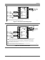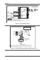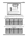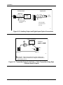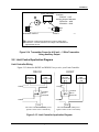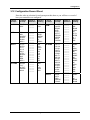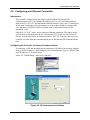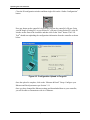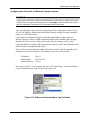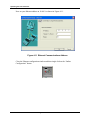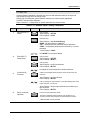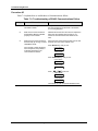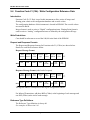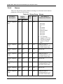
1
UDC2500
Universal Digital Controller
Limit Control Model
Product Manual
51-52-25-118
March 2007
Honeywell Process Solutions
Industrial Measurement and Control
Notices and Trademarks
Copyright 2007 by Honeywell
Revision 5 March 2007
WARRANTY/REMEDY
Honeywell warrants goods of its manufacture as being free of defective materials and faulty
workmanship. Contact your local sales office for warranty information. If warranted goods are
returned to Honeywell during the period of coverage, Honeywell will repair or replace without charge
those items it finds defective. The foregoing is Buyer's sole remedy and is in lieu of all other
warranties, expressed or implied, including those of merchantability and fitness for a
particular purpose. Specifications may change without notice. The information we supply is
believed to be accurate and reliable as of this printing. However, we assume no responsibility for its
use.
While we provide application assistance personally, through our literature and the Honeywell web
site, it is up to the customer to determine the suitability of the product in the application.
Honeywell Process Solutions
Industrial Measurement and Control
512 Virginia Drive
Fort Washington, PA 19034
UDC2500 is a U.S. registered trademark of Honeywell
Other brand or product names are trademarks of their respective owners.
ii
UDC2500 Universal Digital Limit ControllerProduct Manual
3/07
About This Document
Abstract
This document provides descriptions and procedures for the Installation, Configuration, Operation, and Troubleshooting of
your UDC2500 Controller.
Contacts
World Wide Web
The following lists Honeywell’s World Wide Web sites that will be of interest to our customers.
Honeywell Organization
WWW Address (URL)
Corporate
http://www.honeywell.com
Industrial Measurement and Control
http://www.honeywell.com/ps
Technical tips
http://content.honeywell.com/ipc/faq
Telephone
Contact us by telephone at the numbers listed below.
Organization
United States and Canada
3/07
Honeywell
Phone Number
1-800-423-9883
1-800-525-7439
UDC2500 Universal Digital Limit ControllerProduct Manual
Tech. Support
Service
iii
Symbol Definitions
The following table lists those symbols used in this document to denote certain conditions.
Symbol
Definition
This CAUTION symbol on the equipment refers the user to the Product Manual for
additional information. This symbol appears next to required information in the manual.
WARNING
PERSONAL INJURY: Risk of electrical shock. This symbol warns the user of a
potential shock hazard where HAZARDOUS LIVE voltages greater than 30 Vrms, 42.4
Vpeak, or 60 VDC may be accessible. Failure to comply with these instructions
could result in death or serious injury.
ATTENTION, Electrostatic Discharge (ESD) hazards. Observe precautions for
handling electrostatic sensitive devices
Protective Earth (PE) terminal. Provided for connection of the protective earth (green
or green/yellow) supply system conductor.
Functional earth terminal. Used for non-safety purposes such as noise immunity
improvement. NOTE: This connection shall be bonded to protective earth at the source
of supply in accordance with national local electrical code requirements.
Earth Ground. Functional earth connection. NOTE: This connection shall be bonded to
Protective earth at the source of supply in accordance with national and local electrical
code requirements.
Chassis Ground. Identifies a connection to the chassis or frame of the equipment shall
be bonded to Protective Earth at the source of supply in accordance with national and
local electrical code requirements.
iv
UDC2500 Universal Digital Limit ControllerProduct Manual
3/07
Contents
1
INTRODUCTION ................................................................................................... 1
1.1
Overview.........................................................................................................................................1
1.1.1 Function of keys...................................................................................................................3
1.2
Process Instrument Explorer Software............................................................................................4
1.3
CE Conformity (Europe).................................................................................................................6
2
INSTALLATION..................................................................................................... 7
2.1
Overview.........................................................................................................................................7
2.2
Condensed Specifications ...............................................................................................................8
2.3
Model Number Interpretation .......................................................................................................11
2.4
Limit and Alarm Relay Contact Information ................................................................................13
2.5
Mounting.......................................................................................................................................14
2.6
Wiring ...........................................................................................................................................16
2.6.1 Electrical Considerations ...................................................................................................16
2.7
Wiring Diagrams...........................................................................................................................18
2.8
Limit Control Application Diagram..............................................................................................25
3
CONFIGURATION............................................................................................... 26
3.1
Overview.......................................................................................................................................26
3.2
Configuration Prompt Hierarchy ..................................................................................................27
3.3
Configuration Procedure...............................................................................................................28
3.4
Lock Set Up Group .......................................................................................................................29
3.5
Limit Set Up Group ......................................................................................................................30
3.6
Input 1 Set Up Group....................................................................................................................31
3.7
Options Set Up Group...................................................................................................................35
3.8
Communications Set Up Group ....................................................................................................37
3.9
Alarms Set Up Group....................................................................................................................40
3.10
Display Set Up Group ...............................................................................................................44
3.11
P.I.E. Tool Ethernet and Email Configuration Screens.............................................................46
3.12
Configuration Record Sheet ......................................................................................................49
4
OPERATING THE LIMIT CONTROLLER ........................................................... 50
4.1
Overview.......................................................................................................................................50
4.2
Operator Interface .........................................................................................................................51
4.3
Entering a Security Code ..............................................................................................................51
4.4
Lockout Feature ............................................................................................................................52
3/07
UDC2500 Universal Digital Limit ControllerProduct Manual
v
4.5
Monitoring Your Limit Controller................................................................................................53
4.6
Operating Your Limit Controller ..................................................................................................55
4.7
Alarm Setpoints ............................................................................................................................58
4.8
P.I.E. Tool Maintenance Screens ..................................................................................................59
4.9
Configuring your Ethernet Connection.........................................................................................65
5
INPUT CALIBRATION......................................................................................... 70
5.1
Overview.......................................................................................................................................70
5.2
Minimum and Maximum Range Values .......................................................................................71
5.3
Preliminary Information................................................................................................................73
5.4
Input 1 Set Up Wiring...................................................................................................................74
5.5
Input 1 Calibration Procedure.......................................................................................................79
5.6
Restore Input Factory Calibration.................................................................................................80
6
OUTPUT CALIBRATION..................................................................................... 83
6.1
Overview.......................................................................................................................................83
6.2
Auxiliary Output Calibration ........................................................................................................83
6.3
Restore Output Factory Calibration ..............................................................................................85
7
TROUBLESHOOTING/SERVICE........................................................................ 87
7.1
Overview.......................................................................................................................................87
7.2
Troubleshooting Aids....................................................................................................................88
7.3
Power-up Tests..............................................................................................................................90
7.4
Status Tests ...................................................................................................................................90
7.5
Background Tests..........................................................................................................................91
7.6
Controller Failure Symptoms........................................................................................................93
7.7
Troubleshooting Procedures .........................................................................................................94
7.8
Restoring Factory Configuration ................................................................................................100
8
PARTS LIST ...................................................................................................... 101
8.1
Exploded View............................................................................................................................101
8.2
Removing the chassis..................................................................................................................103
9
vi
MODBUS RTU FUNCTION CODES.................................................................. 104
9.1
Overview.....................................................................................................................................104
9.2
General Information....................................................................................................................104
9.3
Function Code 20 (14h) - Read Configuration Reference Data..................................................106
9.3.1 Read Configuration Examples .........................................................................................108
9.4
Function Code 21 (15h) - Write Configuration Reference Data.................................................110
UDC2500 Universal Digital Limit ControllerProduct Manual
3/07
9.4.1
Write Configuration Examples ........................................................................................112
10
MODBUS READ, WRITE AND OVERRIDE PARAMETERS PLUS EXCEPTION
CODES........................................................................................................................ 113
10.1
Overview .................................................................................................................................113
10.2
Reading Control Data..............................................................................................................115
10.3
Miscellaneous Read Onlys ......................................................................................................115
10.3.1
Register Addresses for Read Onlys ..............................................................................115
10.4
Configuration Parameters........................................................................................................116
10.4.1
Lock..............................................................................................................................116
10.4.2
Limit .............................................................................................................................117
10.4.3
Input 1...........................................................................................................................118
10.4.4
Options .........................................................................................................................120
10.4.5
Communications...........................................................................................................121
10.4.6
Alarms ..........................................................................................................................122
10.4.7
Display..........................................................................................................................124
10.5
11
Modbus RTU Exception Codes...............................................................................................125
ETHERNET TCP/IP ........................................................................................... 127
11.1
12
Overview .................................................................................................................................127
FURTHER INFORMATION................................................................................ 128
12.1
Modbus RTU Serial Communications ....................................................................................128
12.2
Modbus Messaging on TCP/IP................................................................................................128
12.3
How to Apply Digital Instrumentation in Severe Electrical Noise Environments..................128
13
INDEX ................................................................................................................ 129
14
SALES AND SERVICE...................................................................................... 132
3/07
UDC2500 Universal Digital Limit ControllerProduct Manual
vii
Tables
Table 2-1 Condensed Specifications _____________________________________________________ 8
Table 2-2 Limit Relay Contact Information _______________________________________________ 13
Table 2-3 Alarm Relay Contact Information ______________________________________________ 13
Table 2-4 Mounting Procedure_________________________________________________________ 15
Table 2-5 Permissible Wiring Bundling__________________________________________________ 17
Table 2-6 Terminals for connecting a UDC to a MDI Compliant Hub or Switch __________________ 23
Table 2-7 Terminals for connecting a UDC directly to a PC utilizing a straight-through cable ________ 23
Table 3-1 Configuration Topics ________________________________________________________ 26
Table 3-2 Configuration Prompt Hierarchy _______________________________________________ 27
Table 3-3 Configuration Procedure _____________________________________________________ 28
Table 3-4 LOCK Group Function Prompts _______________________________________________ 29
Table 3-5 LIMIT Group Function Prompts _______________________________________________ 30
Table 3-6 INPUT 1 Group Function Prompts _____________________________________________ 31
Table 3-7 OPTION Group Function Prompts _____________________________________________ 35
Table 3-8 Communications Group Function Prompts _______________________________________ 37
Table 3-9 ALARMS Group Function Prompts ____________________________________________ 40
Table 3-10 DISPLY Group Function Prompts _____________________________________________ 44
Table 4-1 Procedure to Enter a Security Code _____________________________________________ 52
Table 4-2 Annunciators ______________________________________________________________ 53
Table 4-3 Error Messages_____________________________________________________________ 54
Table 4-4 Using Contact Input Option ___________________________________________________ 57
Table 4-5 Procedure for Displaying Alarm Setpoints _______________________________________ 58
Table 5-1 Voltage, Milliamp and Resistance Equivalents for Input 1 Range Values _______________ 71
Table 5-2 Equipment Needed __________________________________________________________ 73
Table 5-3 Set Up Wiring Procedure for Thermocouple Inputs Using an Ice Bath _________________ 74
Table 5-4 Set Up Wiring Procedure for Thermocouple Inputs using Thermocouple Source _________ 75
Table 5-5 Set Up Wiring Procedure for RTD Inputs ________________________________________ 75
Table 5-6 Wiring Connections for Radiamatic, Thermocouple Differential, Millivolts or Volts (Except 0 to 10
Volts) _________________________________________________________________________ 76
Table 5-7 Set Up Wiring Procedure for 0 to 10 Volts _______________________________________ 77
Table 5-8 Set Up Wiring Procedure for Milliampere Inputs __________________________________ 78
Table 5-9 Input 1 Calibration Procedure _________________________________________________ 79
Table 5-10 Restore Input Factory Calibration _____________________________________________ 81
Table 6-1 Set Up Wiring Procedure for Auxiliary Output ____________________________________ 84
Table 6-2 Auxiliary Output Calibration Procedure _________________________________________ 85
Table 6-3 Restore Factory Calibration ___________________________________________________ 86
Table 7-1 Procedure for Identifying the Software Version ___________________________________ 89
Table 7-2 Procedure for Displaying the Status Test Results __________________________________ 90
Table 7-3 Background Tests___________________________________________________________ 91
Table 7-4 Controller Failure Symptoms__________________________________________________ 93
Table 7-5 Troubleshooting Power Failure Symptoms _______________________________________ 95
Table 7-6 Troubleshooting Latching Output Relay Failure ___________________________________ 96
Table 7-7 Troubleshooting Alarm Relay Output Failure _____________________________________ 96
Table 7-8 Troubleshooting a Keyboard Failure ____________________________________________ 97
Table 7-9 Troubleshooting a RS-485 Communications Failure________________________________ 98
Table 7-10 Troubleshooting Auxiliary Output Failure ______________________________________ 99
Table 7-11 Restoring Factory Configuration _____________________________________________ 100
Table 8-1 Parts Identification _________________________________________________________ 102
viii
UDC2500 Universal Digital Limit ControllerProduct Manual
3/07
Table 8-2 Parts Not Shown___________________________________________________________ 102
Table 9-1 Integer Parameter Type _____________________________________________________ 105
Table 9-2 Floating Point Parameter Type________________________________________________ 105
Table 9-3 Register Address Format for Function Code 20___________________________________ 107
Table 9-4 Register Address Format for Function Code 21___________________________________ 111
Table 10-1 Control Data Parameters ___________________________________________________ 115
Table 10-2 Miscellaneous Read Onlys__________________________________________________ 115
Table 10-3 Set-up Group Lock________________________________________________________ 116
Table 10-4 Set-up Group Limit _______________________________________________________ 117
Table 10-5 Set-up Group – Input 1_____________________________________________________ 118
Table 10-6 Set-up Group – Options ____________________________________________________ 120
Table 10-7 Set-up Group – Communications_____________________________________________ 121
Table 10-8 Set-up Group – Alarms ____________________________________________________ 122
Table 10-9 Set-up Group – Display ____________________________________________________ 124
Table 10-10 Modbus RTU Data Layer Status Exception Codes ______________________________ 126
3/07
UDC2500 Universal Digital Limit ControllerProduct Manual
ix
Figures
Figure 1-1 UDC2500 Operator Interface __________________________________________________ 2
Figure 1-2 Screen capture of Process Instrument Explorer running on a Pocket PC _________________ 4
Figure 1-3 Depiction of infrared communications ___________________________________________ 5
Figure 2-1 Model Number Interpretation _________________________________________________ 12
Figure 2-2 Mounting Dimensions (not to scale)____________________________________________ 14
Figure 2-3 Mounting Method __________________________________________________________ 15
Figure 2-4 Composite Wiring Diagram __________________________________________________ 18
Figure 2-5 Mains Power Supply________________________________________________________ 19
Figure 2-6 Input 1 Connections ________________________________________________________ 20
Figure 2-7 Electromechanical Relay Output ______________________________________________ 21
Figure 2-8 Solid State Relay Output ____________________________________________________ 21
Figure 2-9 Open Collector Output ______________________________________________________ 22
Figure 2-10 RS-422/485 Communications Option Connections _______________________________ 22
Figure 2-11 Ethernet Communications Option Connections __________________________________ 23
Figure 2-12 Auxiliary Output and Digital Inputs Option Connections __________________________ 24
Figure 2-13 Transmitter Power for 4-20 mA — 2 wire Transmitter Using Open Collector Alarm 2 Output24
Figure 2-14 Transmitter Power for 4-20 mA — 2 Wire Transmitter Using Auxiliary Output ________ 25
Figure 2-15 Limit Controller Application Diagram _________________________________________ 25
Figure 3-1 Ethernet Configuration Screen ________________________________________________ 46
Figure 3-2 Email Configuration Screen __________________________________________________ 47
Figure 4-1 Operator Interface __________________________________________________________ 51
Figure 4-2 Maintenance Data Menu_____________________________________________________ 59
Figure 4-2 Loop Data Maintenance Screen _______________________________________________ 60
Figure 4-3 Alarm Details Maintenance Screen ____________________________________________ 61
Figure 4-4 Status Data Maintenance Screen_______________________________________________ 63
Figure 4-5 Ethernet Status Maintenance Screen____________________________________________ 64
Figure 4-6 IR Communications Address _________________________________________________ 65
Figure 4-7 Configuration Upload in Progress _____________________________________________ 66
Figure 4-8 Ethernet Communications Type Selection _______________________________________ 67
Figure 4-9 Ethernet Communications Address ____________________________________________ 68
Figure 4-10 Configuration Upload in Progress ____________________________________________ 69
Figure 5-1 Input 1 Wiring Terminals ____________________________________________________ 73
Figure 5-2 Wiring Connections for Thermocouple Inputs Using an Ice Bath _____________________ 74
Figure 5-3 Wiring Connections for Thermocouple Inputs Using Thermocouple Source ____________ 75
Figure 5-4 Wiring Connections for RTD (Resistance Thermometer Device) _____________________ 75
Figure 5-5 Wiring Connections for Radiamatic, Millivolts, Volts or Thermocouple Differential (Except 0 to 10
Volts) _________________________________________________________________________ 76
Figure 5-6 Wiring Connections for 0 to 10 Volts___________________________________________ 77
Figure 5-7 Wiring Connections for 0 to 20 mA or 4 to 20 mA Inputs ___________________________ 78
Figure 6-1 Wiring Connections for Calibrating Auxiliary Output ______________________________ 84
Figure 8-1 UDC2500 Exploded View __________________________________________________ 101
x
UDC2500 Universal Digital Limit ControllerProduct Manual
3/07
Introduction
1 Introduction
1.1 Overview
Function
UDC2500 Limit Controllers accept input signals from any of several types of external
sensors such as Thermocouples (T/Cs) and Resistance Temperature Detectors (RTDs). It
conditions these signals, as necessary, to derive the equivalent Process Variable (PV)
value that drives various circuits in the controller.
The equivalent PV signal is compared with the Limit control set point and any error
signal from the differential amplifier de-energizes the coil of an electromechanical,
single-pole, dual-throw (SPDT) limit output relay.
When de-energized, the output relay “Locks Out” and remains that way until the PV
input signal drops below the High Limit Set Point or goes above the Low Limit Set Point
and the controller is reset manually via the keyboard or from a remote location (Contact
Input Option).
The contact of the output relay terminates at the rear terminal of the controller to which
you make the appropriate field wiring connections.
A flashing “LIMIT” in the lower display indicates that the output relay is de-energized.
Features
•
90 – 264 Vac or 24 Vac/dc Power Supply
•
Input/Output Isolation
•
Isolated Auxiliary Current Output / Digital Inputs
•
Modbus® RS-485 or Ethernet TCP/IP Communications
High Limit Controller
When the PV input signal is below the limit set point, the output relay energizes. If the
PV signal exceeds the limit set point, the output relay de-energizes and the flashing
“LIMIT” display is turned on.
When the PV signal returns to a value below the limit set point, the controller can be
reset manually using the RESET key or Contact Input Option.
Low Limit Controller
When the PV input signal is above the limit set point, the output relay energizes. If the
PV signal falls below the limit set point, the output relay de-energizes and the flashing
“LIMIT” display is turned on.
3/07
UDC2500 Universal Digital Limit ControllerProduct Manual
1
Introduction
When the PV signal returns to a value above the limit set point, the controller can be reset
manually using the RESET key or Contact Input Option.
Easy to read displays
The dedicated vacuum fluorescent displays with multi-language prompts make the
operator interface easy to read, understand and operate. Programmed sequences of
displays assure quick and accurate entry of all configurable parameters.
Easy to operate
Simple keystrokes let you select input and range configuration, set the operating
parameters that meet you process control needs now, and change them later to meet new
ones.
Mount anywhere
This instrument is intended for industrial control applications. It must be panel mounted
with the wiring terminals enclosed within the panel. The instrument is environmentally
hardened and, when suitably enclosed, can be mounted anywhere in plant or factory, on
the wall, or even on the process machine itself. The front face is NEMA3 and IP55 rated
and can be easily upgraded to NEMA4X and IP66 for the most severe hose-down
applications. It withstands ambient temperatures up to 55°C (133°F) and resists the
effects of vibration and shock.
Figure 1-1 UDC2500 Operator Interface
2
UDC2500 Universal Digital Limit ControllerProduct Manual
3/07
Introduction
1.1.1 Function of keys
Table 1-1 shows each key on the operator interface and defines its function.
Table 1-1 Function of Keys
Key
Setup
Function
Lower
Display
M-A
Reset
SP
Select
Run
Hold
Function
• Places the controller in the Configuration Set Up group select mode.
Sequentially displays Set Up groups and allows the FUNCTION key to
display individual functions in each Set Up group.
• Used in conjunction with the SET UP key to select the individual functions of
a selected Configuration Set Up group.
• Used during field calibration procedure.
• Selects an operating parameter to be shown in the lower display.
MAN-AUTO This function is not available on the Limit Controller.
RESET Reset the Limit Relay.
This key does not function on the Limit Controller
• Acknowledges a latched alarm 1.
• Acknowledges Diagnostic Messages.
• Increases the selected parameter value.
• Decreases the selected parameter value.
3/07
UDC2500 Universal Digital Limit ControllerProduct Manual
3
Introduction
1.2 Process Instrument Explorer Software
Overview
Process Instrument Explorer lets you configure your instrument on a desktop/laptop or
Pocket PC. For details see Process Instrument Explorer manual #51-52-25-131.
Features
•
Create configurations with intuitive software program running on either a Pocket
PC, a Desktop or a laptop computer. ·
•
Create/edit configurations live, just connect software to controller via comm port.·
•
Create/edit configurations offline and download to controller later via comm. port.·
•
Port types available on every UDC2500:·
o infrared,·
o RS 485,
o Ethernet.
•
Same port types on UDC3200 and UDC3500 allow interconnectivity.
•
This software is available in English, Spanish, Italian, German and French.
Figure 1-2 Screen capture of Process Instrument Explorer running
on a Pocket PC
4
UDC2500 Universal Digital Limit ControllerProduct Manual
3/07
Introduction
Infrared communications
The infrared connection provides a non-intrusive wireless connection with the instrument
and maintains NEMA4X AND IP66 integrity.
No need to get access to the back of the controller to communicate with the instrument,
no need to take your screw driver to wire the communication cable, no wiring mistake
possible. You can now duplicate an instrument’s configuration, upload or download a
new configuration in a matter of seconds, just by pointing your Pocket PC in the direction
of the instrument.
It takes just a few seconds to upload a configuration from an instrument. You can then
save the configuration file onto your PC or pocket PC for review, modification or
archiving. Furthermore, this software also gives you important maintenance information
on the controller : instantly, get information on the current operating parameters, digital
inputs and alarm status, identify internal or analog input problems.
Question: What if I have several controllers on the same panel? How can I be sure I am
communicating with the correct one?
Answer: The infrared port of the controller is normally “off”. You activate the infrared
port by pressing any controller’s key. You can now communicate. After 4 minutes, the
port will be shut down again. Also, in the Communications Group “IR ENABLE” may be
disabled to prohibit IR communications.
Figure 1-3 Depiction of infrared communications
3/07
UDC2500 Universal Digital Limit ControllerProduct Manual
5
Introduction
1.3 CE Conformity (Europe)
This product is in conformity with the protection requirements of the following European
Council Directives: 73/23/EEC, the Low Voltage Directive, and 89/336/EEC, the EMC
Directive. Conformity of this product with any other “CE Mark” Directive(s) shall not be
assumed.
Product Classification: Class I: Permanently connected, panel-mounted Industrial
Control Equipment with protective earthing (grounding) (EN61010-1).
Enclosure Rating: This controller must be panel-mounted with the rear terminals
enclosed within the panel. The front panel of the controller is rated at NEMA4X and IP66
when properly installed.
Installation Category (Overvoltage Category): Category II (EN61010-1)
Pollution Degree: Pollution Degree 2: Normally non-conductive pollution with
occasional conductivity caused by condensation. (Ref. IEC 664-1)
EMC Classification: Group 1, Class A, ISM Equipment (EN61326, emissions), Industrial
Equipment (EN61326, immunity)
Method of EMC Assessment: Technical File (TF)
Declaration of Conformity: 51453655
Deviation from the installation conditions specified in this manual, and the special
conditions for CE conformity in Subsection 2.6, may invalidate this product’s conformity
with the Low Voltage and EMC Directives.
ATTENTION
The emission limits of EN61326 are designed to provide reasonable protection
against harmful interference when this equipment is operated in an industrial
environment. Operation of this equipment in a residential area may cause harmful
interference. This equipment generates, uses, and can radiate radio frequency
energy and may cause interference to radio and television reception when the
equipment is used closer than 30 meters (98 feet) to the antenna (e). In special
cases, when highly susceptible apparatus is used in close proximity, the user may
have to employ additional mitigating measures to further reduce the
electromagnetic emissions of this equipment.
WARNING
If this equipment is used in a manner not specified by the manufacturer, the
protection provided by the equipment may be impaired.
6
UDC2500 Universal Digital Limit ControllerProduct Manual
3/07
Installation
2 Installation
2.1 Overview
Introduction
Installation of the UDC2500 consists of mounting and wiring the controller according to
the instructions given in this section. Read the pre-installation information, check the
model number interpretation (Subsection 2.3), and become familiar with your model
selections, then proceed with installation.
What’s in this section?
The following topics are covered in this section.
TOPIC
3/07
See Page
2.1 Overview
7
2.2 Condensed Specifications
8
2.3 Model Number Interpretation
11
2.4 Control and Alarm Relay Contact Information
13
2.5 Mounting
14
2.6 Wiring
16
2.7 Wiring Diagrams
Composite Wiring Diagram
AC Line Voltage
Input 1 Connections
Relay Output
Electromechanical
Solid State
Open Collector
RS-422/485 Communications Option
Ethernet Communications Option
Auxiliary Output and Digital Inputs Option
Transmitter Power using Open Collector Output
Transmitter Power using Auxiliary Output
18
18
19
20
2.8 Limit Control Application Diagram
25
UDC2500 Universal Digital Limit ControllerProduct Manual
21
21
22
22
23
24
24
25
7
Installation
Pre-installation Information
If the controller has not been removed from its shipping carton, inspect the carton for
damage then remove the controller.
•
Inspect the unit for any obvious shipping damage and report any damage due to
transit to the carrier.
•
Make sure a bag containing mounting hardware is included in the carton with the
controller.
•
Check that the model number shown on the inside of the case agrees with what you
have ordered.
2.2 Condensed Specifications
Honeywell recommends that you review and adhere to the operating limits listed in Table
2-1 when you install your controller.
Table 2-1 Condensed Specifications
Analog Inputs
Accuracy:
± 0.25% of full scale typical (± 1 digit for display)
Can be field calibrated to ± 0.05% of full scale typical
16-bit resolution typical
Sampling Rate: Both inputs are sampled six times per second
Temperature Stability: ± 0.01% of Full Scale span / ˚C change—typical
Input Impedance:
4-20 Milliampere Input: 250 ohms
0-10 Volt Input: 200K ohms
All Others: 10 megohms
Maximum Lead Wire Resistance:
Thermocouples: 50 ohms/leg
100 ohm, 200 ohm and 500 ohm RTD: 100 ohms/leg
100 ohm Low RTD: 10 ohms/leg
Analog Input Signal
Failure Operation
Burnout Selections: Upscale, Downscale
Thermocouple Health: Good, Failing, Failure Imminent or Failed
Stray Rejection
Common Mode
AC (50 or 60 Hz): 120 dB (with maximum source impedance of 100 ohms) or ± 1 LSB (least
significant bit) whichever is greater with line voltage applied.
DC: 120 dB (with maximum source impedance of 100 ohms) or a ±1 LSB whichever is
greater with 120 Vdc applied.
DC (to 1 KHz): 80 dB (with maximum source of impedance of 100 ohms) or ±1 LSB
whichever is greater with 50 Vac applied.
Normal Mode
AC (50 or 60 Hz): 60 dB (with 100 % span peak-to-peak maximum)
Digital Inputs (One)
(Optional)
8
+30 Vdc source for external dry contacts or isolated solid state contacts. Digital Inputs are
isolated from line power, earth ground, analog inputs and all outputs except for the Second
Current Output.
UDC2500 Universal Digital Limit ControllerProduct Manual
3/07
Installation
Controller Output
Types
Alarm Outputs
(Optional)
Isolation (Functional)
Electromechanical Relay
SPDT contacts. Both Normally Open and Normally Closed contacts are brought out to the
rear terminals. Internally socketed.
Resistive Load: 5 amps @ 120 Vac or 240 Vac or 30 Vdc
Inductive Load (cosϕ = 0.4): 3 amps @ 130 Vac or 250 Vac
Inductive Load (L/R = 7 msec): 3.5 amps @ 30 Vdc
Motor: 1/6 H.P.
Solid State Relay
Zero-crossing type SPST solid state contacts consisting of a triac N.O. output. Internally
socketed.
Resistive Load: 1.0 amp @ 25°C and 120 or 240 Vac, 0.5 amp @ 55°C and 120 or 240 Vac
Inductive Load: 50 VA @ 120 Vac or 240 Vac
Minimum Load: 20 milliamps
Open Collector Outputs (One or Two)
Socketed assembly replacing a relay. Opto-isolated from all other circuits except current
output and not from each other. Internally powered @ 30 Vdc.
Note: Applying an external power supply to this output will damage the instrument.
Maximum Sink Current: 20 mA
Short-circuit current limit: 100 mA
One or two SPDT Electromechanical relays.
Up to four setpoints are independently set as high or low alarm, two for each relay. Setpoint
can be on Process Variable, Deviation, PV Rate, Communication Shed or Thermocouple
Health. A single adjustable hysteresis of 0.0 to 100.0% is provided.
Alarm Relay Contacts Rating: Resistive Load: 5 amps at 120 Vac or 240 Vac or 30 Vdc
Analog Inputs: are isolated from all other circuits at 850Vdc for 2 seconds, but not from each
other.
Analog Outputs: are isolated from all other circuits at 850Vdc for 2 seconds.
AC Power: is electrically isolated from all other inputs and outputs to withstand a HIPOT
potential of 1900Vdc for 2 seconds per Annex K of EN61010-1.
Relay Contacts: with a working voltage of 115/230 Vac, are isolated from each other and all
other circuits at 345Vdc for 2 seconds.
RS422/485 Modbus
RTU
Communications
Interface (Optional)
Baud Rate: 4800, 9600,19,200 or 38,400 baud selectable
Data Format: Floating point or integer
Length of Link:
2000 ft (600 m) max. with Belden 9271 Twinax Cable and 120 ohm termination resistors
4000 ft. (1200 m) max. with Belden 8227 Twinax Cable and 100 ohm termination resistors
Link Characteristics: Two-wire, multi-drop Modbus RTU protocol, 15 drops maximum or up
to 31 drops for shorter link length.
Ethernet TCP/IP
Communications
Interface (Optional)
Type: 10Base-T
Length of Link: 330 ft. (100 m) maximum
Link Characteristics: Four-wire, single drop, five hops maximum
IP Address: IP Address is 10.0.0.2 as shipped from the Factory
Recommended network configuration: Use Switch rather than Hub in order to maximize
UDC Ethernet performance
Infrared
Communications
(Optional)
Type: Serial Infrared (SIR)
Length of Link: 3 ft. (1 m) maximum for IrDA 1.0 compliant devices
Baud Rate: 19,200 or 38,400 baud selectable
Power Consumption
20 VA maximum (90 to 264 Vac)
15 VA maximum (24 Vac/dc)
Power Inrush Current 10A maximum for 4 ms (under operating conditions), reducing to a maximum of 225 mA (90
to 264 Vac operation) or 750 mA (24 Vac/dc operation) after one second.
CAUTION
When applying power to more than one instrument, make sure that sufficient
power is supplied. Otherwise, the instruments may not start up normally due to voltage drop
from the inrush current.
Weight
3/07
3 lbs. (1.3 kg)
UDC2500 Universal Digital Limit ControllerProduct Manual
9
Installation
Environmental and Operating Conditions
Parameter
Reference
Rated
Operative
Limits
Transportation and
Storage
Ambient Temperature
25 ± 3 °C
77 ± 5 °F
15 to 55 °C
58 to 131 °F
0 to 55 °C
32 to 131 °F
–40 to 66 °C
–40 to 151 °F
Relative Humidity
10 to 55*
10 to 90*
5 to 90*
5 to 95*
Vibration
Frequency (Hz)
Acceleration (g)
0
0
0 to 70
0.4
0 to 200
0.6
0 to 200
0.5
Mechanical Shock
Acceleration (g)
Duration (ms))
0
0
1
30
5
30
20
30
Line Voltage (Vdc)
+24 ± 1
22 to 27
20 to 27
--
120 ± 1
240 ± 2
90 to 240
90 to 264
---
24 ± 1
20 to 27
20 to 27
--
50 ± 0.2
60 ± 0.2
49 to 51
59 to 61
48 to 52
58 to 62
---
Line Voltage (Vac)
90 to 240 Vac
24 Vac
Frequency (Hz)
(For Vac)
* The maximum moisture rating only applies up to 40 °C (104 °F). For higher temperatures, the RH specification is
derated to maintain constant moisture content.
10
UDC2500 Universal Digital Limit ControllerProduct Manual
3/07
Installation
2.3 Model Number Interpretation
Introduction
Write your controller’s model number in the spaces provided below and circle the corresponding
items in each table. This information will also be useful when you wire your controller.
KEY NUMBER - UDC2500 Single Loop Controller
Description
Digital Controller for use with 90 to 264Vac Power
Digital Controller for use with 24Vac/dc Power
TABLE I - Specify Control Output and/or Alarms
Selection Availability
DC2500
DC2501
Availability
DC 2500 2501
Selection
Electro Mechanical Relay (5 Amp Form C)
Solid State Relay (1 Amp)
Open Collector transistor output
E_
A_
T_
No Additional Outputs or Alarms
One Alarm Relay Only
Output #2 and Alarm
E-M Relay (5 Amp Form C) Plus Alarm 1 (5 Amp Form C Relay)
#1 or Alarms 1 and 2
Solid State Relay (1 Amp) Plus Alarm 1 (5 Amp Form C Relay)
Open Collector Plus Alarm 1 (5 Amp Form C Relay)
_0
_B
_E
_A
_T
Output #1
Availability
DC 2500 2501
TABLE II - Communications and Software Selections
Communications
Selection
None
Auxiliary Output/Digital Inputs (1 Aux and 1 DI or 2 DI)
RS-485 Modbus Plus Auxiliary Output/Digital Inputs
10 Base-T Ethernet (Modbus RTU) Plus Auxiliary Output/Digital Inputs
0___
1___
2___
3___
Limit Controller
No Selection
_L__
__0_
None
Infrared Interface Included (Can be used with a Pocket PC)
___0
___R
Software Selections
Reserved
Infrared interface
Availability
DC 2500 2501
TABLE III - Input 1 can be changed in the field using external resistors
Input 1
Input 2
TC, RTD, mV, 0-5V, 1-5V
TC, RTD, mV, 0-5V, 1-5V, 0-20mA, 4-20mA
TC, RTD, mV, 0-5V, 1-5V, 0-20mA, 4-20mA, 0-10V
None
Selection
1__
2__
3__
_ 00
Availability
DC 2500 2501
TABLE IV - Options
Approvals
Tags
Future Options
Selection
CE, UL and CSA (Standard)
CE, UL, CSA and FM
None
Stainless Steel Customer ID Tag - 3 lines w/22 characters/line
None
None
None
0____
1____
_0___
_T___
__0__
___0_
____0
b
b
continued
3/07
UDC2500 Universal Digital Limit ControllerProduct Manual
11
Installation
TABLE V - Product Manuals
Manuals
Certificate
Availability
DC 2500 2501
Selection
Product Information on CD - All Languages
English Manual
(51-52-25-127)
French Manual
(51-52-25-127-FR)
German Manual
(51-52-25-127-DE)
Italian Manual
(51-52-25-127-IT)
Spanish Manual
(51-52-25-127-SP)
None
Certificate of Conformance (F3391)
0_
E_
F_
G_
I_
S_
_0
_C
Limit Controller Restrictions/Comments:
1. FM approved units with communications are limited to read only.
2. FM approved units are restricted to TC and RTD type inputs.
3. UL listed for regulatory use only.
_L_
b
II
c
Input 2 Not Available with Limit Model
Figure 2-1 Model Number Interpretation
12
UDC2500 Universal Digital Limit ControllerProduct Manual
3/07
Installation
2.4 Limit and Alarm Relay Contact Information
Limit Relay
ATTENTION
The Limit relay is designed to operate in a Failsafe mode. This results in momentary
(5 seconds maximum) limit action when power is initially applied, until the unit completes selfdiagnostics. If power is lost to the unit, the Limit Control Relay will still function.
Table 2-2 Limit Relay Contact Information
Unit
Power
Limit
Control
Relay
Wiring
Off
On
Variable NOT in Limit State
Variable in Limit State
Relay
Contact
Indicators
Relay
Contact
Indicators
N.O.
Open
Off
Open
Off
N.C.
Closed
N.O.
Closed
N.C.
Open
Closed
Off
Open
On
Closed
Alarm Relays
ATTENTION
Alarm relays are designed to operate in a failsafe mode (that is, de-energized during alarm
sate). This results in alarm actuation when power is OFF or when initially applied, until the unit
completes self diagnostics. If power is lost to the unit, the alarms will de-energize and thus the
alarm contacts will close.
Table 2-3 Alarm Relay Contact Information
Unit
Power
Alarm Relay
Wiring
Off
On
3/07
Variable NOT in Alarm State
Variable in Alarm State
Relay
Contact
Indicators
Relay
Contact
Indicators
N.O.
Open
Off
Open
Off
N.C.
Closed
N.O.
Closed
N.C.
Open
Closed
Off
Open
On
Closed
UDC2500 Universal Digital Limit ControllerProduct Manual
13
Installation
2.5 Mounting
Physical Considerations
The controller can be mounted on either a vertical or tilted panel using the mounting kit
supplied. Adequate access space must be available at the back of the panel for installation
and servicing activities.
•
Overall dimensions and panel cutout requirements for mounting the controller are
shown in Figure 2-2.
•
The controller’s mounting enclosure must be grounded according to CSA standard
C22.2 No. 0.4 or Factory Mutual Class No. 3820 paragraph 6.1.5.
•
The front panel is moisture rated NEMA3 and IP55 rated and can be easily upgraded
to NEMA4X and IP66.
Overall Dimensions
Max. panel thickness
19,1
9,0
.75
0,35
mm
inches
92,0 + 0,8
- 0,00
3,62 + 0,03
-0,00
90,6
3,57
108,6
4,28
Panel
Cutout
92,0 + 0,8
- 0,00
3,62 + 0,03
-0,00
17,9
0,70
113,1
4,45
Figure 2-2 Mounting Dimensions (not to scale)
14
UDC2500 Universal Digital Limit ControllerProduct Manual
3/07
Installation
Mounting Method
Before mounting the controller, refer to the nameplate on the outside of the case and
make a note of the model number. It will help later when selecting the proper wiring
configuration.
Mounting Clips
Attach screws and
washers here for
water protection
Figure 2-3 Mounting Method
Mounting Procedure
Table 2-4 Mounting Procedure
Step
Action
1
Mark and cut out the controller hole in the panel according to the dimension
information in Figure 2-2.
2
Orient the case properly and slide it through the panel hole from the front.
3
Remove the mounting kit from the shipping container and install the kit as follows:
•
For normal installation two mounting clips are required. Insert the prongs of the
clips into the two holes in the top and bottom center of the case (Figure 2-3).
•
For water-protected installation four mounting clips are required. There are two
options of where to install the mounting clips: 1) Insert the prongs of the clips into
the two holes on the left and right side of the top and bottom of the case or 2) on
the center on each of the four sides (Figure 2-3).
Tighten screws to 2 lb-inch (22 N•cm) to secure the case against the panel.
CAUTION: Over tightening will cause distortion and the unit may not seal properly.
•
4
3/07
For water-protected installations, install four screws with washers into the four
recessed areas in the corners of the bezel (Figure 2-3). Push the point of the screw
through the center piercing the elastomeric material and then tighten screws to 5 lb-in
(56 N•cm).
UDC2500 Universal Digital Limit ControllerProduct Manual
15
Installation
2.6 Wiring
2.6.1 Electrical Considerations
Line voltage wiring
This controller is considered “rack and panel mounted equipment” per EN61010-1,
Safety Requirements for Electrical Equipment for Measurement, Control, and Laboratory
Use, Part 1: General Requirements. Conformity with 72/23/EEC, the Low Voltage
Directive requires the user to provide adequate protection against a shock hazard. The
user shall install this controller in an enclosure that limits OPERATOR access to the rear
terminals.
Mains Power Supply
This equipment is suitable for connection to 90 to 264 Vac or to 24 Vac/dc 50/60 Hz,
power supply mains. It is the user’s responsibility to provide a switch and non-time delay
(North America), quick-acting, high breaking capacity, Type F (Europe), 1/2A, 250V
fuse(s), or circuit-breaker for 90-264 Vac applications; or 1 A, 125 V fuse or circuit
breaker for 24 Vac/dc applications, as part of the installation. The switch or circuitbreaker shall be located in close proximity to the controller, within easy reach of the
OPERATOR. The switch or circuit-breaker shall be marked as the disconnecting device
for the controller.
CAUTION
Applying 90-264 Vac to an instrument rated for 24 Vac/dc will severely
damage the instrument and is a fire and smoke hazard.
When applying power to multiple instruments, make certain that sufficient current is
supplied. Otherwise, the instruments may not start up normally due to the voltage drop
caused by the in-rush current.
Controller Grounding
PROTECTIVE BONDING (grounding) of this controller and the enclosure in which it is
installed shall be in accordance with National and Local electrical codes. To minimize
electrical noise and transients that may adversely affect the system, supplementary
bonding of the controller enclosure to a local ground, using a No. 12 (4 mm2) copper
conductor, is recommended.
Control/Alarm Circuit Wiring
The insulation of wires connected to the Control/Alarm terminals shall be rated for the
highest voltage involved. Extra Low Voltage (ELV) wiring (input, current output, and
low voltage Control/Alarm circuits) shall be separated from HAZARDOUS LIVE (>30
Vac, 42.4 Vpeak, or 60 Vdc) wiring per Permissible Wiring Bundling, Table 2-5.
16
UDC2500 Universal Digital Limit ControllerProduct Manual
3/07
Installation
Electrical Noise Precautions
Electrical noise is composed of unabated electrical signals which produce undesirable
effects in measurements and control circuits.
Digital equipment is especially sensitive to the effects of electrical noise. Your controller
has built-in circuits to reduce the effect of electrical noise from various sources. If there
is a need to further reduce these effects:
•
Separate External Wiring—Separate connecting wires into bundles
(See Permissible Wiring Bundling - Table 2-5) and route the individual bundles
through separate conduit metal trays.
Use Suppression Devices—For additional noise protection, you may want to add
suppression devices at the external source. Appropriate suppression devices are
commercially available.
ATTENTION
For additional noise information, refer to document number 51-52-05-01, How to Apply Digital
Instrumentation in Severe Electrical Noise Environments.
Permissible Wiring Bundling
Table 2-5 Permissible Wiring Bundling
Bundle No.
1
2
3
3/07
Wire Functions
• Line power wiring
• Earth ground wiring
• Line voltage control relay output wiring
• Line voltage alarm wiring
Analog signal wire, such as:
• Input signal wire (thermocouple, 4 to 20 mA, etc.)
• 4-20 mA output signal wiring
Digital input signals
• Low voltage alarm relay output wiring
• Low voltage wiring to solid state type control circuits
• Low voltage wiring to open collector type control circuits
UDC2500 Universal Digital Limit ControllerProduct Manual
17
Installation
2.7 Wiring Diagrams
Identify Your Wiring Requirements
To determine the appropriate diagrams for wiring your controller, refer to the model
number interpretation in this section. The model number of the controller can be found on
the outside of the case.
Wiring the Controller
Using the information contained in the model number, select the appropriate wiring
diagrams from the composite wiring diagram below. Refer to the individual diagrams
listed to wire the controller according to your requirements.
Auxiliary Output
Output
Auxiliary
and
and Digital
Digital Inputs
Inputs
Terminals
Terminals
See Figure
Figure 2-17
2-12
See
ACLine
LineVoltage
Voltage
AC
Terminals
Terminals
See Figure
Figure 2-5
2-5
See
Outputs 3 and 4
Terminals
Outputs
3 and
4
See
Figure
2-7 thru
Terminals
Figure 2-9
See Figures 2-8
through 2-14
10
19
L1
11
20
L2/N
12
21
4
13
22
5
14
23
6
15
24
7
16
25
8
17
26
9
18
27
Limit
Limit Relay
Relay
Terminals
Terminals
See
Figure
2-72-8
thru
See
Figures
Figure
2-9
through 2-14
Not
Used
Input #1
Terminals
See Figure 2-6
Communications
ComTerminals
munications
Terminals
See Figure
2-10 and
See Figures
2-15
and 2-16
Figure
2-11
xxxx
Figure 2-4 Composite Wiring Diagram
18
UDC2500 Universal Digital Limit ControllerProduct Manual
3/07
Installation
1
3
AC/DC
Line
Voltage
2
Ground
10
19
L1
11
20
L2/N
12
21
4
13
22
5
14
23
6
15
24
7
16
25
8
17
26
9
18
Hot
Neutral
27
1 PROTECTIVE BONDING (grounding) of this controller and the enclosure in which it is
installed, shall be in accordance with National and local electrical codes. To minimize
electrical noise and transients that may adversely affect the system, supplementary
2
bonding of the controller enclosure to local ground using a No. 12 (4 mm ) copper
conductor is recommended. Before powering the controller, see “Prelimnary Checks”
in this section of the Product Manual.
2 It is the user’s responsibility to provide a switch and non-time delay (North America),
quick-acting, high breaking capacity, Type F (Europe), 1/2A, 250V fuse(s), or circuitbreaker for 90-264 Vac applications; or 1 A, 125 V fuse or circuit breaker for 24 Vac/dc
applications, as part of the installation.
3 CAUTION Applying 90-264 Vac to an instrument rated for 24 Vac/dc will severely
damage the instrument and is a fire and smoke hazard.
xxxx
Figure 2-5 Mains Power Supply
3/07
UDC2500 Universal Digital Limit ControllerProduct Manual
19
Installation
Input #1
Thermocouple
Millivolt or Volts
except 0-10 Volts
RTD
Use Thermocouple
extension wire only
25 R
25 R
26 +
26 +
27 –
27 –
source
25 R
3
0-10 Volts
0–10
Volt
source
+
1
–
mV or
Volt
source
Milliamps
100K 1
2
100K 3
25 R
26 +
27 –
+
1
250 Ω
Power
+
–
Supply
26 +
–
27 –
Thermocouple Differential
25 R
–
Xmitter
+
26 +
27 –
Use Thermocouple
extension wire only
+
26 +
–
–
+
25 R
2
27 –
1
The 250 ohm resistor for milliamp inputs or the voltage divider for 0-10 Volt inputs are supplied
with the controller when those inputs are specified. These items must be installed prior to start
up when the controller is wired. For 0-20 mA applications, the resistor should be located at the
transmitter terminals if Burnout detection is desired.
2
Splice and tape this junction between the two thermocouples. This junction may be located
anywhere between the thermocouples and the instrument terminals, it does not need to be close
to the other thermocouple junctions. Both thermocouples must be of the same type. For best
accuracy, the two thermocouples should be matched or, preferably, made from the same batch
of wire.
3
This controller does not produce a steady current for burnout detection. For that reason, when a
thermocouple is used in parallel with another instrument, it may be desirable to configure the
burnout selection for this controller to “NOFS” and use the burnout current from the other
instrument to also drive this controller.
xxxx
Figure 2-6 Input 1 Connections
20
UDC2500 Universal Digital Limit ControllerProduct Manual
3/07
Installation
19
L1
Output
Relay#1
N.C.
20
21
L2/N
4
Load
Supply
Power
Relay Load
2
To terminal
4 or 6
5
Relay Load
1
To terminal
7 or 9
Alarm
N.O. Relay#2
8
1
23
24
6
7
Load
Supply
Power
To terminal
19 or 21
22
N.C.
Load
Supply
Power
Relay Load
N.O.
25
N.C.
Alarm
N.O. Relay#1
26
9
27
1 Electromechanical relays are rated at Amps @120 Vac or 30 Vdc and 2.5 Amps at 240 Vac.
Customer should size fuses accordingly. Use Fast Blo fuses only.
xxxx
Figure 2-7 Electromechanical Relay Output
Dummy Resistor
1
19
L1
Output
Relay#1
4
Relay Load
2
To terminal
4 or 6
5
Relay Load
3
To terminal
7 or 9
N.C. Alarm
Relay#2
N.O.
8
9
22
Load
Supply
Power
2
23
24
6
7
Load
Supply
Power
Relay Load
21
L2/N
Load
Supply
Power
20
N.O.
N.C. Alarm
Relay#1
N.O.
25
26
27
1
If the load current is less than the minimum rated value of 20 mA, then there may be residual voltage across both
ends of the load even if the relay is turned off. Use a dummy resistor as shown to counteract this. The total
current through the resistor and the the load must exceed 20 mA. Solid State Relays are zero-crossing type.
2
Solid State relays are rated at 1 Amp at 25°C and derated linearly to 0.5 Amp at 55°C. Customer should size
fuse accordingly. Use Fast Blo fuses only.
3
Electromechanical relays are rated at 5 Amps @120 Vac or 30 Vdc and 2.5 Amps at 240 Vac.
Customer should size fuses accordingly. Use Fast Blo fuses only.
xxxxx
Figure 2-8 Solid State Relay Output
3/07
UDC2500 Universal Digital Limit ControllerProduct Manual
21
Installation
Time Simplex
Customer Supplied
Electromechanical relay
19
L1
L2/N
+
20
Output #1
1 –
21
4
Load
Supply
Power
Relay Load
2
Load
Supply
Power
1
2
5
To terminal
4 or 6
7
N.C. Alarm
Relay#1
N.O.
8
To terminal
7 or 9
22
–
Customer Supplied
Solid-State relay
23
24
6
Relay Load
2
N.C. Alarm
Relay#2
N.O.
+
+
–
9
25
26
27
CAUTION Open collector outputs are internally powered at +30 Vdc. Connecting an external
power supply will damage the controller.
Electromechanical relays are rated at 5 Amps @120 Vac or 30 Vdc and 2.5 Amps at 240 Vac.
Customer should size fuses accordingly. Use Fast Blo fuses only.
xxxx
Figure 2-9 Open Collector Output
COMMUNICATION MASTER
D+ (B) SHLD
1
16 SHLD
D– (A)
2
SHLD
17 D+ (B)
D+
18 D– (A)
D–
120 OHMS
TO OTHER
COMMUNICATION
CONTROLLERS
D–
Connect shield
to ground at one
end only.
D+
120 OHMS ON LAST LEG
1 Do not run the communications lines in the same conduit as AC power.
2 Use shielded twisted pair cables (Belden 9271 Twinax or equivalent).
xxxx
Figure 2-10 RS-422/485 Communications Option Connections
22
UDC2500 Universal Digital Limit ControllerProduct Manual
3/07
Installation
COMMUNICATION MASTER
OR SWITCH
3
TXD+ TXDRXD- RXD–
SHLD TXD–
RXD+ TXD+
RXD+
1
SHLD
1414
SHLD
2
1515
RXD
+
RXD+
–1616
RXD
RXD
1717
TXD
+
TXD+
TXD–1818
TXD
1 Do not run the communications lines in the same conduit as AC
power. Correct connections may require the use of an Ethernet
cross-over cable.
2
Use Shielded twisted-pair, Category 5 (STP CAT5) Ethernet cable.
3
Use Switch rather than Hub to maximize performance.
Figure 2-11 Ethernet Communications Option Connections
Figure 2-11 and Table 2-6 shows how to connect a UDC to a MDI Compliant Hub or
Switch utilizing a straight-through cable or for connecting a UDC to a PC utilizing a
crossover cable.
Table 2-6 Terminals for connecting a UDC to a MDI Compliant Hub or Switch
UDC Terminal
UDC Signal Name
RJ45 Socket Pin #
Switch Signal
Name
Position 14
Shield
Shield
Shield
Position 15
RXD-
6
TXD-
Position 16
RXD+
3
TXD+
Position 17
TXD-
2
RXD-
Position 18
TXD+
1
RXD+
Table 2-7 shows how to connect a UDC directly to a PC utilizing a straight-through cable
(wiring the UDC cable this way makes the necessary cross-over connections)
Table 2-7 Terminals for connecting a UDC directly to a PC utilizing a straightthrough cable
3/07
UDC Terminal
UDC Signal Name
RJ45 Socket Pin #
PC Signal Name
Position 14
Shield
Shield
Shield
Position 15
RXD-
2
TXD-
Position 16
RXD+
1
TXD+
Position 17
TXD-
6
RXD-
Position 18
TXD+
3
RXD+
UDC2500 Universal Digital Limit ControllerProduct Manual
23
Installation
Digital Inputs
Auxiliary Output
12
13
+
_
+
Auxiliary
Load
0 - 1000 Ω
10
11
12
13
Digital
Input #1
_
Connect shield
to ground at one
end only.
Connect shield
to ground at one
end only.
xxxx
Figure 2-12 Auxiliary Output and Digital Inputs Option Connections
2 Wire Transmitter
1
+
5+
6OUTPUT 3
_
250 Ω
Configure:
A2S1TY = NONE
A2S2TY = NONE
26 +
27 INPUT 1
xxxx
1 If necessary, install a zener diode here to reduce voltage at the
transmitter. A 1N4733 will reduce the voltage at the transmitter to
approximately 25 Vdc.
Figure 2-13 Transmitter Power for 4-20 mA — 2 wire Transmitter Using Open
Collector Alarm 2 Output
24
UDC2500 Universal Digital Limit ControllerProduct Manual
3/07
Installation
2 Wire Transmitter
1
_
+
12 +
250 Ω
13 AUXILIARY OUTPUT
Configure:
AUXOUT = OUT
Auxiliary Output Calibration
ZEROVAL = 4095
SPANVAL = 4095
26 +
27 INPUT 1
xxxx
1 If necessary, install a zener diode here to reduce voltage at the
transmitter. A 1N4733 will reduce the voltage at the transmitter to
approximately 25 Vdc.
Figure 2-14 Transmitter Power for 4-20 mA — 2 Wire Transmitter
Using Auxiliary Output
2.8 Limit Control Application Diagram
Limit Controller Wiring
Figure 2-15 shows the RIGHT and WRONG way to wire your Limit Controller.
WRONG
PROCESS
CONTROLLER
LIMIT
CONTROLLER
POWER
RIGHT
PROCESS
CONTROLLER
LIMIT
CONTROLLER
POWER
1
2
CONTROL
RELAY/
SOLENOID
POWER
1
2
CONTROL
RELAY/
SOLENOID
POWER
LOAD
The Limit Controller CANNOT protect
against a failure of the Control Relay
LOAD
The Limit Controller CAN protect
against a failure of the Control Relay
Figure 2-15 Limit Controller Application Diagram
3/07
UDC2500 Universal Digital Limit ControllerProduct Manual
25
Configuration
3 Configuration
3.1 Overview
Introduction
Configuration is a dedicated operation where you use straightforward keystroke
sequences to select and establish (configure) pertinent control data best suited for your
application.
To assist you in the configuration process, there are prompts that appear in the upper and
lower displays. These prompts let you know what group of configuration data (Set Up
prompts) you are working with and also, the specific parameters (Function prompts)
associated with each group.
Table 3-1 shows an overview of the prompt hierarchy as it appears in the controller.
What’s in this section?
The following topics are covered in this section.
Table 3-1 Configuration Topics
TOPIC
3.1
3.2
3.3
3.4
3.5
3.6
3.7
3.8
3.9
3.10
3.11
3.12
26
Overview
Configuration Prompt Hierarchy
Configuration Procedure
Tuning Set Up Group
Limit Set Up Group
Input 1 Set Up Group
Options Set Up Group
Communications Set Up Group
Alarms Set Up Group
Display Set Up Group
P.I.E. Tool Ethernet and Email Configuration Screens
Configuration Record Sheet
UDC2500 Universal Digital Limit ControllerProduct Manual
See Page
26
27
28
29
30
31
35
37
40
44
46
49
3/07
Configuration
3.2 Configuration Prompt Hierarchy
Table 3-2 Configuration Prompt Hierarchy
Set Up Group
Function Prompts
LOCK
SECUR
LOCK
LIMIT
LOorHI
POWRUP
SPMAX
SPMIN
DISPLY
INPUT1
IN1TYP
XMITR1
IN1 HI
IN1 LO
BIAS 1
FILTR1
BRNOUT
EMISS
OPTIONS
DIGIN1
AUXOUT
COM
ComADR
ComSTA
IRENAB
BAUD
SDENAB
SHDTIM
BAUD
TX DLY
WS FLT
UNITS
LOOPBK
A1S1TY
A1S1VA
A1S1HL
A1S1TY
A1S1VA
A1S1HL
A1S1TY
A1S1VA
A1S1HL
A1S1TY
A1S1VA
A1S1HL
ALHYST
ALARM1
BLOCK
DIAGAL
DISPLY
DECMAL
UNITS
FREQ
LWRDSP
TCDIAG
STATUS
VERSON
FAILSF
TESTS
ALARMS
3/07
UDC2500 Universal Digital Limit ControllerProduct Manual
27
Configuration
3.3 Configuration Procedure
Introduction
Each of the Set Up groups and their functions are pre-configured at the factory.
The factory settings are shown in Section 3.12.
If you want to change any of these selections or values, follow the procedure in Table
3-3. This procedure tells you the keys to press to get to any Set Up group and any
associated Function parameter prompt.
Procedure
ATTENTION
The prompting scrolls at a rate of 2/3 seconds when the SET UP or FUNCTION key is held in.
Also,
or
keys will move group prompts forward or backward at a rate twice as fast.
Table 3-3 Configuration Procedure
Step
Operation
Press
1
Enter Set Up
Mode
Setup
2
Select any Set
Up Group
Setup
3
Select a Function
Parameter
Function
Result
Upper Display = SET
Lower Display = LOCK (This is the first Set Up Group title)
Sequentially displays the other Set Up group titles shown in
the prompt hierarchy in Table 3-2 Configuration Prompt
Hierarchy.
You can also use the
or
keys to scan the Set Up
groups in both directions. Stop at the Set Up group title that
describes the group of parameters you want to configure.
Then proceed to the next step.
Upper Display = the current value or selection for the first
function prompt of the selected Set Up
group.
Lower Display = the first Function prompt within that Set Up
group.
Sequentially displays the other function prompts of the Set
Up group you have selected. Stop at the function prompt
that you want to change, then proceed to the next step.
28
4
Change the
Value or
Selection
5
Enter the Value
or Selection
6
Exit Configuration
or
Function
Lower
Display
Increments or decrements the value or selection that
appears for the selected function prompt. If you change the
value or selection of a parameter while in Set Up mode then
decide not to enter it, press M-A/RESET once—the original
value or selection is recalled.
Enters value or selection made into memory after another
key is pressed.
Exits configuration mode and returns controller to the same
state it was in immediately preceding entry into the Set Up
mode. It stores any changes you have made.
If you do not press any keys for 30 seconds, the controller
times out and reverts to the mode and display used prior to
entry into Set Up mode.
UDC2500 Universal Digital Limit ControllerProduct Manual
3/07
Configuration
3.4 Lock Set Up Group
Introduction
The Lock Set Up group contains the Function parameters that will allow your controller
to protect Configuration and Calibration data.
Because this group contains functions that have to do with Security and Lockout, it is
best to configure this group last, after all the other configuration data has been loaded.
Function Prompts
Table 3-4 LOCK Group Function Prompts
Function Prompt
Lower Display
Selection or Range of Setting
Upper Display
Parameter
Definition
SECUR
0 to 4095
When “LOCK” is configured as “NONE”, the
Security Code number is displayed and can
be changed using the raise/lower keys
LOCK
NONE
NONE – all parameters are read/write
CAL
CAL - all parameters are read/write except
Calibration
CONF
CONF – configuration parameters are Read
Only; no writes permitted
+SP
+SP – Only the Lockout group is available for
read/write. Setpoint value is Read Only.
3/07
UDC2500 Universal Digital Limit ControllerProduct Manual
29
Configuration
3.5 Limit Set Up Group
Introduction
This data deals with the type of Limit Control you want, power up Logic, setpoint high
and low limits, and the default display function Prompts
Table 3-5 LIMIT Group Function Prompts
Function Prompt
Lower Display
Selection or Range of Setting
Upper Display
Parameter
Definition
LOW
LOW - Limit Control - latching relay deenergizes when PV goes below configured
setpoint; cannot be reset until PV rises
above configured setpoint and M-A RESET
key is pressed.
HIGH
HIGH - Limit Control - latching relay deenergizes when PV goes above configured
setpoint; cannot be reset until PV drops
below configured setpoint and M-A RESET
key is pressed.
RST
RST - after power down, the controller
latching relay will have to be reset.
NORM
NORM - after power down, the controller will
operate normally in the same mode as
before power was removed unless a limit has
been exceeded. If the limit was latched at
power down, the unit will be in “Limit” at
power up and have to be reset.
SP_MAX
0 % to 100 % of input in
engineering units
HIGH SETPOINT LIMIT - this selection
prevents the setpoint from going above the
value selected here. The setting must be
equal to or less than the upper range of the
input.
SP_MIN
0 % to 100 % of input in
engineering units
LOW SETPOINT LIMIT - this selection
prevents the setpoint from going below the
value selected here. The setting must be
equal to or greater than the lower range of
the input.
DISPLY
PROC
PROC - Process Variable - PV will be
displayed in the upper display.
SP
SP - Setpoint - if configured the setpoint will
be displayed in the upper display. “SP” will
appear in the lower display.
LOorHI
POWRUP
30
UDC2500 Universal Digital Limit ControllerProduct Manual
3/07
Configuration
3.6 Input 1 Set Up Group
Introduction
This data deals with various parameters required to configure Input 1.
Function Prompts
Table 3-6 INPUT 1 Group Function Prompts
Function Prompt
Lower Display
Selection or Range of Setting
Upper Display
IN1TYP
Parameter
Definition
INPUT 1 ACTUATION TYPE – This
selection determines what actuation you are
going to use for Input 1.
B
EH
EL
JH
JM
JL
KH
KM
KL
NNMH
NNML
NICH
NICL
R
S
TH
TL
WH
WL
100H
100L
200
500
RADH
RADI
0-20
4-20
10m
50m
100m
0-5
1-5
0-10
TDIF
PR
B—B Thermocouple
E H—E Thermocouple High
E L—E Thermocouple Low
J H—J Thermocouple High
J M—J Thermocouple Med
J L—J Thermocouple Low
K H—K Thermocouple High
K M—K Thermocouple Med
K L—K Thermocouple Low
NNMH—Ni-Ni-Moly Thermocouple High
NNML—Ni-Ni-Moly Thermocouple Low
NICH—Nicrosil-Nisil Thermocouple High
NICL—Nicrosil-Nisil Thermocouple Low
R—R Thermocouple
S—S Thermocouple
T H—T Thermocouple High
T L—T Thermocouple Low
W H—W5W26 Thermocouple High
W L—W5W26 Thermocouple Low
100H—100 Ohm RTD High
100L—100 Ohm RTD Low
200—200 Ohm RTD
500—500 Ohm RTD
RADH—Radiamatic RH
RADI—Radiamatic RI
0-20—0 to 20 Milliamperes *
4-20—4 to 20 Milliamperes *
10m—0 to 10 Millivolts *
50m—0 to 50 Millivolts *
100m—0 to 100 Millivolts *
0-5—0 to 5 Volts *
1-5—1 to 5 Volts *
0-10—0 to 10 Volts *
TDIF—Thermocouple Differential *
PR—PR40-PR20 Thermocouple
* These input types are not available on
FM Models.
3/07
UDC2500 Universal Digital Limit ControllerProduct Manual
31
Configuration
Function Prompt
Lower Display
XMITR1
IN1 HI
Selection or Range of Setting
Upper Display
B
EH
EL
JH
JM
JL
KH
KM
KL
NNMH
NNML
NICH
NICL
R
S
TH
TL
WH
WL
100H
100L
200
500
RADH
RADI
LIN
SrT
−999 to 9999 floating in
engineering units
Parameter
Definition
TRANSMITTER CHARACTERIZATION—
This selection lets you instruct the controller
to characterize a linear input to represent a
non-linear one. If characterization is
performed by the transmitter itself, then
select LIN (Linear).
ATTENTION Prompt only appears when a
linear actuation is selected at prompt IN1
TYPE.
FOR EXAMPLE:
If input 1 is a 4 to 20 mA signal, but the
signal represents a type K H thermocouple,
then configure K H and the controller will
characterize the 4 to 20 mA signal so that it
is treated as a type K thermocouple input
(high range).
Parameter definitions are the same as in IN1
TYPE.
ATTENTION Not available on FM Models.
INPUT 1 HIGH RANGE VALUE in
engineering units is displayed for all inputs
but can only be configured for linear or
square root transmitter characterization.
Scale the #1 input signal to the display value
you want for 100 %.
EXAMPLE:
Process Variable = Flow
Range of Flow = 0 to 250 Liters/Minute
Actuation (Input 1) = 4 to 20 mA
Characterization (XMITTER) = LINEAR
Set IN1 HI display value to 250
Set IN1 LO display value to 0
Then 20 mA = 250 Liters/Minute
and 4 mA = 0 Liters/Minute
ATTENTION The range of the Limit
setpoint will be limited by the range of units
selected here.
32
UDC2500 Universal Digital Limit ControllerProduct Manual
3/07
Configuration
Function Prompt
Lower Display
IN1 LO
Selection or Range of Setting
Upper Display
−999 to 9999 floating in
engineering units
Parameter
Definition
INPUT 1 LOW RANGE VALUE in
engineering units is displayed for all inputs
but can only be configured for linear or
square root transmitter characterization.
Scale the #1 input signal to the display value
you want for 0 %. See example above.
ATTENTION The control setpoint for Input
1 will be limited by the range of units
selected here.
BIAS 1
−999 to 9999 floating in
engineering units for Non-FM
Models
-10 to 10 floating in engineering
units for FM Models
FILTR1
0 to 120 seconds
0 = No Filter
BIAS ON INPUT 1 — Bias is used to
compensate the input for drift of an input
value due to deterioration of a sensor, or
some other cause. Select the bias value you
want on Input 1.
FILTER FOR INPUT 1—A software digital
filter is provided for Input 1 to smooth the
input signal. You can configure the first order
lag time constant from 1 to 120 seconds. If
you do not want filtering, enter 0.
BURNOUT PROTECTION (SENSOR
BREAK) provides most input types with
upscale or downscale protection if the input
fails.
BRNOUT
UP
UPSCALE BURNOUT will force the Input 1
signal to the full scale value when the sensor
fails. Diagnostic message IN1 FAIL
intermittently flashed on the lower display.
The controller remains in Automatic control
mode and adjusts the controller output signal
in response to the full scale Input 1 signal
developed by the Burnout circuitry.
DOWN
DOWNSCALE BURNOUT will force the
Input 1 signal to the lower range value when
the sensor fails. Diagnostic message IN1
FAIL intermittently flashed on the lower
display.
ATTENTION For Burnout to function
properly on a 0-20 mA input type (or a 0-5V
type that uses a dropping resistor), the
dropping resistor must be remotely located
(across the transmitter terminals).
Otherwise, the input at the UDC terminals
will always be 0 mA (i.e., within the normal
operating range) when the 0-20 mA line is
opened.
3/07
UDC2500 Universal Digital Limit ControllerProduct Manual
33
Configuration
Function Prompt
Lower Display
EMISS
34
Selection or Range of Setting
Upper Display
0.01 to 1.00
Parameter
Definition
EMISSIVITY is a correction factor applied to
the Radiamatic input signal that is the ratio of
the actual energy emitted from the target to
the energy which would be emitted if the
target were a perfect radiator.
Available only for Radiamatic inputs.
UDC2500 Universal Digital Limit ControllerProduct Manual
3/07
Configuration
3.7
Options Set Up Group
Introduction
The Options group lets you configure the remote mode switch (Digital Inputs) to a
specific contact closure response, or configure the Auxiliary Output to be a specific
selection with desired scaling.
Function Prompts
Table 3-7 OPTION Group Function Prompts
Function Prompt
Lower Display
Selection or Range of Setting
Upper Display
Parameter
Definition
AUXILIARY OUTPUT SELECTION
This selection provides an mA output
representing one of several control
parameters. The display for auxiliary output
viewing will be in engineering units for all but
output. Output will be displayed in percent.
AUXOUT
ATTENTION Other prompts affected by
these selections: 4mA VAL and 20mA VAL.
ATTENTION Output cannot be configured
when Three Position Step Control is used.
NONE
NO AUXILIARY OUTPUT
PROC
PROCESS VARIABLE—Represents the
value of the Process Variable. PV = Input
XxRatioX + BiasX
DEV
DEVIATION (PROCESS VARIABLE
MINUS SETPOINT)—Represents –100 %
to +100 % of the selected PV span in
engineering units.
Zero deviation will produce a center scale
(12 mA or 50 %) output. A negative deviation
equal in magnitude to the Auxiliary Output
High Scaling Factor will produce a low end
output (4 mA or 0 %) output. A positive
deviation equal in magnitude to the Auxiliary
Output Low Scaling Factor will produce a
high end output (20 mA or 100 %).
FOR EXAMPLE:
Input 1 = Type T High Thermocouple
PV range = –300 °F to +700 °F
PV span = 1000 °F
Deviation Range = –1000 °F to +1000 °F
Auxiliary Output Low Scale Value = 0.0
Auxiliary Output High Scale Value = 1000
If PV = 500 °F and SP = 650 °F
then Deviation Display = –150 °F, which
is
–7.5% of the Deviation Range, so
Auxiliary Output = 50% – 7.5% = 42.5%
3/07
UDC2500 Universal Digital Limit ControllerProduct Manual
35
Configuration
Function Prompt
Lower Display
0_PCT
Selection or Range of Setting
Upper Display
Parameter
Definition
Value in Engineering Units
AUXILIARY OUTPUT LOW SCALING
FACTOR—Use a value in engineering units
to represent all AUX OUT parameters except
output.
Use value in percent (%) for output. (Output
can be between –5 % and +105 %.)
100 PCT
Value in Engineering Units
AUXILIARY OUTPUT HIGH SCALING
FACTOR—Use a value in engineering units
to represent all AUX OUT parameters except
output.
Use a value in percent (%) for Output.
(Output can be between –5 % and +105 %.)
CRANGE
4-20
0-20
AUXILIARY OUTPUT RANGE allows the
user to easily select 4-20mA output or 020mA output operation without the need for
recalibration of the instrument.
ATTENTION Changing the Auxiliary
Output Range will result in the loss of Field
Calibration values and will restore Factory
Calibration values.
DIGIN1
DIGITAL INPUT 1 SELECTIONS—All
selections are available for Input 1. The
controller returns to its original state when
contact opens, except when overruled by the
keyboard.
EXTERNAL RESET (DIGITAL INPUT) —
resets the latching relay on contact closure.
36
DIS
DIS – Disable
ENAB
ENAB – Enable
UDC2500 Universal Digital Limit ControllerProduct Manual
3/07
Configuration
3.8
Communications Set Up Group
Introduction
The Communications group lets you configure the controller to be connected to a host
computer via Modbus® or Ethernet TCP/IP protocol.
Introduction
A controller with a communications option looks for messages from the host computer. If
these messages are not received within the configured shed time, the controller will
SHED from the communications link and return to stand-alone operation. You can also
set the SHED output mode and setpoint recall, and communication units.
Up to 99 addresses can be configured over this link. The number of units that can be
configured depends on the link length, with 31 being the maximum for short link lengths
and 15 drops being the maximum at the maximum link length.
ATTENTION
FM Models cannot have parameters changed (write transactions) via communications,
parameters can only be changed via the keyboard.
Function Prompts
Table 3-8 Communications Group Function Prompts
Function Prompt
Lower Display
ComADR
Selection or Range of
Setting
Upper Display
1 to 99
COMSTA
IRENAB
COMMUNICATIONS STATION ADDRESS—This
is a number that is assigned to a controller that is
to be used with the communications option. This
number will be its address. This parameter is also
used for the IR communications link.
COMMUNICATIONS SELECTION
DIS
MODB
ETHR
DISABLE—Disables the communications option
MODBUS—Enable Modbus RTU communications
ETHERN—Enable Ethernet Communications
DIS
EnAB
INFRARED COMMUNICATIONS –
Enables/Disables the IR Port.
BAUD RATE is the transmission speed in bits per
second.
BAUD
4800
9600
19200
38400
3/07
Parameter
Definition
4800 BAUD
9600 BAUD
19200 BAUD
38400 BAUD
UDC2500 Universal Digital Limit ControllerProduct Manual
37
Configuration
Function Prompt
Lower Display
TX_DLY
Selection or Range of
Setting
Upper Display
1 to 500 milliseconds
WS_FLT
Parameter
Definition
TX DELAY—Configurable response-delay timer
allows you to force the UDC to delay its response
for a time period of from 1 to 500 milliseconds
compatible with the host system
hardware/software. This parameter is also used for
the IR communications link.
Defines word/byte order of floating point data for
communications. Byte values:
0
1
2
3
seeeeeee emmmmmmm mmmmmmmm mmmmmmmm
Where:
s = sign, e = exponent, m = mantissa bit
FP B
FPBB
FP L
FPLB
0
1
3
2
1
0
2
3
2
3
1
0
3
2
0
1
SDENAB
DIS
EnAB
SHED ENABLE—Disables/enables shed
functionaliy.
SHDTIM
0 to 255 Sample Periods
SHED TIME—The number that represents how
many sample periods there will be before the
controller sheds from communications. Each
period equals 1/3 seconds; 0 equals No shed.
Note: If ComSTA is set to MODBUS and if
SHEDENAB is set to DISABL, Shed Time will not
be configurable.
SHD_SP
SHED SETPOINT RECALL
Note: If SHEDENAB=DISABLE, this prompt will not
be configurable.
UNITS
LSP
TO LSP—Controller will use last local or remote
setpoint used.
CSP
TO CSP—When in “slave” mode, the controller will
store the last host computer setpoint and use it at
the Local setpoint. When in “monitor” mode, the
controller will shed to the last UDC Local or
Remote setpoint used, and the LSP is unchanged.
PCT
EGR
PERCENT
ENGINEERING UNITS
LOOPBK
LOCAL LOOPBACK tests the communications
hardware.
DIS
38
DISABLE—Disables the Loopback test.
UDC2500 Universal Digital Limit ControllerProduct Manual
3/07
Configuration
Function Prompt
Lower Display
Selection or Range of
Setting
Upper Display
ENAB
Parameter
Definition
ENABLE—Allows loopback test. The UDC goes
into Loopback mode in which it sends and receives
its own message. The UDC displays PASS or FAIL
status in the upper display and LOOPBACK in the
lower display while the test is running. The UDC
will go into manual mode when LOOPBACK is
enabled with the output at the Failsafe value. The
test will run until the operator disables it here, or
until power is turned off and on.
ATTENTION The instrument does not have to be
connected to the external communications link in
order to perform this test. If it is connected, only
one instrument should run the loopback test at a
time. The host computer should not be transmitting
on the link while the loopback test is active.
3/07
UDC2500 Universal Digital Limit ControllerProduct Manual
39
Configuration
3.9
Alarms Set Up Group
Introduction
An alarm is an indication that an event that you have configured (for example—Process
Variable) has exceeded one or more alarm limits. There are two alarms available. Each
alarm has two setpoints. You can configure each of these two setpoints to alarm on
various controller parameters.
There are two alarm output selections, High and Low. You can configure each setpoint to
alarm either High or Low. These are called single alarms.
You can also configure the two setpoints to alarm on the same event and to alarm both
high and low. A single adjustable Hysteresis of 0 % to 100 % is configurable for the
alarm setpoint.
See Table 2-3 in the Installation section for Alarm relay contact information.
The prompts for the Alarm Outputs appear whether or not the alarm relays are physically
present. This allows the Alarm status to be shown on the display and/or sent via
communications to a host computer.
Function Prompts
Table 3-9 ALARMS Group Function Prompts
Function Prompt
Lower Display
Selection or Range of Setting
Upper Display
A1S1TY
Parameter
Definition
ALARM 1 SETPOINT 1 TYPE—Select what
you want Setpoint 1 of Alarm 1 to represent.
It can represent the Process Variable,
Deviation, Input 1, Input 2, Output, and if you
have a model with communications, you can
configure the controller to alarm on SHED. If
you have setpoint programming, you can
alarm when a segment goes ON or OFF.
NONE
PROC
DE
SHED
FSAF
PrRT
DI
TC W
TC F
NO ALARM
PROCESS VARIABLE
DEVIATION
SHED FROM COMMUNICATIONS
FAILSAFE
PV RATE OF CHANGE
DIGITAL INPUT 1 ACTUATED
THERMOCOUPLE WARNING (NOTE 1)
THERMOCOUPLE FAILING (NOTE 2)
ATTENTION
NOTE 1. Thermocouple Warning means that
the instrument has detected that the
Thermocouple Input is starting to fail. Not
valid for input types other than
Thermocouple.
NOTE 2. Thermocouple Failing means that
the instrument has detected that the
40
UDC2500 Universal Digital Limit ControllerProduct Manual
3/07
Configuration
Function Prompt
Lower Display
Selection or Range of Setting
Upper Display
Parameter
Definition
Thermocouple Input is in imminent danger of
failing. Not valid for input types other than
Thermocouple.
A1S1VA
Value in engineering units
ALARM 1 SETPOINT 1 VALUE—This is the
value at which you want the alarm type
chosen in prompt A1S1TYPE to actuate. The
value depends on what the setpoint has
been configured to represent. No setpoint is
required for alarms configured for
Communications SHED.
This prompt does not appear for Alarm
Types that do not use values. For example:
A1S1TY = MANUAL.
A1S1HL
ALARM 1 SETPOINT 1 STATE—Select
whether you want the alarm type chosen in
prompt A1S1TYPE to alarm High or Low.
HIGH
LOW
A1S2TY
HIGH ALARM
LOW ALARM
ALARM 1 SETPOINT 2 TYPE—Select what
you want Setpoint 2 of Alarm 1 to represent.
The selections are the same as A1S1TYPE.
A1S2VA
Value in engineering units
ALARM 1 SETPOINT 2 VALUE—This is the
value at which you want the alarm type
chosen in prompt A1S2TYPE to actuate.
The details are the same as A1S1 VAL.
A1S2HL
HIGH
LOW
A2S1TY
ALARM 1 SETPOINT 2 STATE—Same as
A1S1HL.
ALARM 2 SETPOINT 1 TYPE—Select what
you want Setpoint 1 of Alarm 2 to represent.
The selections are the same as A1S1TYPE.
ATTENTION Not applicable with Relay
Duplex unless using Dual Relay PWA.
A2S1VA
Value in engineering units
ALARM 2 SETPOINT 1 VALUE—This is the
value at which you want the alarm type
chosen in prompt A2S1TYPE to actuate.
The details are the same as A1S1 VAL.
A2S1HL
3/07
HIGH
LOW
ALARM 2 SETPOINT 1 STATE—Same as
A1S1HL.
UDC2500 Universal Digital Limit ControllerProduct Manual
41
Configuration
Function Prompt
Lower Display
A2S2TY
Selection or Range of Setting
Upper Display
Value in engineering units
Parameter
Definition
ALARM 2 SETPOINT 2 TYPE—Select what
you want Setpoint 2 of Alarm 2 to represent.
The selections are the same as A1S1TYPE.
ATTENTION Not applicable with Relay
Duplex unless using Dual Relay PWA.
ALARM 2 SETPOINT 2 VALUE—This is the
value at which you want the alarm type
chosen in prompt A2S2TYPE to actuate.
A2S2VA
The details are the same as A1S1 VAL.
A2S1HL
HIGH
LOW
ALARM 2 SETPOINT 1 STATE—Same as
A1S1HL.
ALHYST
0.0 to 100.0 % of span or full
output as appropriate
ALARM HYSTERESIS—A single adjustable
hysteresis is provided on alarms such that
when the alarm is OFF it activates at exactly
the alarm setpoint; when the alarm is ON, it
will not deactivate until the variable is 0.0 %
to 100 % away from the alarm setpoint.
Configure the hysteresis of the alarms based
on INPUT signals as a % of input range
span.
Configure the hysteresis of the alarm based
on OUTPUT signals as a % of the full scale
output range.
ALARM1
LATCHING ALARM OUTPUT 1—Alarm
output 1 can be configured to be Latching or
Non-latching.
NO LAT
LATCH
NO LAT—Non-latching
LATCH—Latching
ATTENTION When configured for latching,
the alarm will stay active after the alarm
condition ends until the RUN/HOLD key is
pressed.
42
UDC2500 Universal Digital Limit ControllerProduct Manual
3/07
Configuration
Function Prompt
Lower Display
Selection or Range of Setting
Upper Display
BLOCK
Parameter
Definition
ALARM BLOCKING—Prevents nuisance
alarms when the controller is first powered
up. The alarm is suppressed until the
parameter gets to the non-alarm limit or
band. Alarm blocking affects both alarm
setpoints.
DIS
AL1
AL 2
AL12
DISABLE—Disables blocking
AL 1—Blocks alarm 1 only
AL 2—Blocks alarm 2 only
AL12—Blocks both alarms
ATTENTION When enabled on power up
or initial enabling via configuration, the alarm
will not activate unless the parameter being
monitored has not been in an alarm condition
for a minimum of one control cycle (167 ms).
DIAGAL
DIAGNOSTIC—Monitors the Current Output
and/or Auxiliary Output for an open circuit
condition. If either of these two outputs falls
below about 3.5 mA, then an Alarm is
activated. This configuration is in addition to
whatever was selected for AxSxTYPE.
DIS
AL 1
AL 2
DISWRN
3/07
DISABLE—Disables Diagnostic Alarm
ALARM 1—Alarm 1 is diagnostic alarm
ALARM 2—Alarm 2 is diagnostic alarm
DISABLE WARNING—Disables Output Fail
message on lower display
UDC2500 Universal Digital Limit ControllerProduct Manual
43
Configuration
3.10 Display Set Up Group
Introduction
This group includes selections for Decimal place, Units of temperature, Language and
Power frequency.
Function Prompts
Table 3-10 DISPLY Group Function Prompts
Function Prompt
Lower Display
Selection or Range of Setting
Upper Display
Parameter
Definition
DECIMAL POINT LOCATION—This
selection determines where the decimal point
appears in the display.
DECMAL
NONE
ONE
TWO
NONE—No Decimal Place—fixed, no autoranging
ONE—888.8
TWO—88.88
ATTENTION Auto-ranging will occur for
selections of one or two decimal places. For
example, should the instrument be
configured for two decimal places and the
PV exceeds 99.99, then the display will
change to a single decimal place so that
values of 100.0 and above can be shown.
TEMPERATURE UNITS—This selection will
affect the indication and operation.
UNITS
F
C
NONE
FREQ
60
50
DEG F—Degrees Fahrenheit
DEG C—Degrees Centigrade
NONE—No display of units
POWER LINE FREQUENCY—Select
whether your controller is operating at 50 or
60 Hertz.
ATTENTION For controllers powered by
+24 Vdc, this configuration should be set to
the AC line frequency used to produce the
+24 Vdc supply.
Incorrect setting of this parameter can cause
normal mode noise problems in the input
readings.
LOWER DISPLY—Select whether the unit
uses single or dual display.
LWRDSP
ENAB
DIS
44
ENAB—Enable Dual Display
DIS—Disable Dual Display (Single Display
Only)
UDC2500 Universal Digital Limit ControllerProduct Manual
3/07
Configuration
Function Prompt
Lower Display
Selection or Range of Setting
Upper Display
THERMOCOUPLE DIAGNOSTICS—Enable
or disable Thermocouple diagnostic
messages.
TCDIAG
ENAB
DIS
3/07
Parameter
Definition
ENAB—Enable Diagnostic Messages
DIS—Disable Diagnostic Messages
UDC2500 Universal Digital Limit ControllerProduct Manual
45
Configuration
3.11 P.I.E. Tool Ethernet and Email Configuration Screens
Introduction
These screens only appear in instruments that have Ethernet Communications. Ethernet
and Email parameters can only be configured via the Process Instrument Explorer (P.I.E.
Tool®). The figures in this section show screen-shots of the Configuration Screens from
the PC version of the P.I.E. Tool®. Pocket PC Configuration Screens are generally
similar in format but smaller.
Ethernet Configuration Screen
This controller is shipped from the factory with the IP Address set to 10.0.0.2, the Subnet
Mask set to 255.255.255.0 and the Default Gateway set to 0.0.0.0. Consult your
Information Technologies (IT) representative as to how these should be configured for
your installation. The MAC address is printed on the product label located on the
instrument’s case.
These settings can be changed via the Ethernet Configuration Screen as shown in Figure
3-1.
See Section 4.9 – Configuring your Ethernet Connection for more information.
Figure 3-1 Ethernet Configuration Screen
46
UDC2500 Universal Digital Limit ControllerProduct Manual
3/07
Configuration
WARNING
After you change the IP Address, you will no longer be able to communicate with the instrument
via Ethernet until you change the P.I.E. Tool’s IP Address setting in the “PC COMM SETUP” to
match the setting that is now in your controller.
Email Configuration Screen
This controller may be configured to support up to two Emails. Each Email can be sent to
a different address. Emails are sent only when the selected alarm transitions from the
OFF to the ON state.
Figure 3-2 Email Configuration Screen
This controller cannot receive Emails, so it is suggested that you configure the “From
Email:” window with a non-Email style address that will make it easy for you to
determine which controller sent the Email. For Email technical reasons, the entry in the
“From Email:” window cannot have spaces. See Figure 3-2.
If you do not know your SMTP IP Address for outgoing Email, then contact your
Information Technologies (IT) representative. If your PC is on the same LAN that will be
used by the controller and which also connects to the Email server, then the SMTP IP
Address may generally be found by opening a DOS shell and typing:
ping smtp.[your domain name and extension], i.e., “ping smtp.your_isp.com”
3/07
UDC2500 Universal Digital Limit ControllerProduct Manual
47
Configuration
The content of the Emails sent by this controller contains the Alarm that triggered the
Email, its settings and the current value (if applicable) of the monitored variable. For
example, the content of an Email triggered by Alarm 1 Setpoint 1 that is configured to
monitor Input 1 would look something like this:
Name: Alarm 1 SP1, Type: INPUT1, Event: HIGH/END, Value = 500.00,
Actual = 712.69
The content of an Email triggered by Alarm 2 Setpoint 1 that is configured to monitor
Digital Input 1 would look something like this:
Name: Alarm 2 SP1, Type: DIG IN1, Event: HIGH/END, Value = 0.00,
Actual = 0.00
ATTENTION
Email will always be time-stamped with the date that the Ethernet Software in the instrument
was last modified.
If the SMTP address on your network is changed, such as can happen when a server is
replaced, then you must reconfigure the Email SMTP IP address in this instrument to match.
48
UDC2500 Universal Digital Limit ControllerProduct Manual
3/07
Configuration
3.12 Configuration Record Sheet
Enter the value or selection for each prompt on this sheet so you will have a record of
how your controller was configured.
Group
Prompt
Function
Prompt
Value or
Selection
Factory
Setting
LOCK
SECUR
LOCK
_______
_______
DIS
CAL
LIMIT
LOW or
HIGH
POWRUP
SP MAX
SP MIN
DISPLY
_______
_______
_______
_______
_______
_______
HIGH
NORM
1000
0
PROC
INPUT1
IN1TYP
XMITR1
IN1 HI
IN1 LO
BIAS 1
FILTR1
BRNOUT
EMIS
FREQ
DISPLY
_______
_______
_______
_______
_______
_______
_______
_______
_______
_______
KH
LIN
2400
1.00
0.0
1.0
UP
1.0
60
SP
OPTIONS
AUXOUT
0 PCT
100 PCT
CRANGE
DIGIN1
_______
_______
_______
_______
_______
DIS
0
100
4-20
DIS
3/07
Group
Prompt
Function
Prompt
Value or
Selection
Factory
Setting
COM
ComADR
ComSTA
IRENAB
BAUD
TX DLY
WS FLT
SDENAB
SHDTIM
UNITS
LOOPBK
_______
_______
_______
_______
_______
_______
_______
_______
_______
_______
3
DIS
ENAB
19200
30
FP_B
ENAB
0
PCT
DIS
ALARMS
A1S1TY
A1S1VA
A1S1HL
A1S2TY
A1S2VA
A1S2HL
A2S1TY
A2S1VA
A2S1HL
A2S2TY
A2S2VA
A2S2HL
ALHYST
ALARM1
BLOCK
DIAGAL
_______
_______
_______
_______
_______
_______
_______
_______
_______
_______
_______
_______
_______
_______
_______
_______
NONE
90
HIGH
NONE
90
HIGH
NONE
90
HIGH
NONE
90
HIGH
0.1
NOL
DIS
DIS
DISPLY
DECML
UNITS
FREQ
LWRDSP
TCDIAG
_______
_______
_______
_______
_______
NONE
F
60
ENAB
ENAB
UDC2500 Universal Digital Limit ControllerProduct Manual
49
Operating the Limit Controller
4 Operating the Limit Controller
4.1 Overview
Introduction
This section gives you all the information necessary to help you monitor your controller
including an Operator Interface overview, how to lockout changes to the controller,
entering a security code, and monitoring the displays.
What's in this section?
The following topics are covered in this section.
TOPIC
50
See Page
4.1 Overview
50
4.2 Operator Interface
51
4.3 Entering A Security Code
51
4.4 Lockout Feature
52
4.5 Monitoring The Limit Controller
53
4.6 How to Operate Your Limit Controller
55
4.7 Alarm Setpoints
58
4.8 P.I.E. Tool Maintenance Screens
59
4.9 Configuring your Ethernet Connection
65
UDC2500 Universal Digital Limit ControllerProduct Manual
3/07
Operating the Limit Controller
4.2 Operator Interface
Introduction
Figure 5-1 is a view of the Operator Interface. A description of the displays and
indicators is included.
Figure 4-1 Operator Interface
4.3 Entering a Security Code
Introduction
The level of keyboard lockout may be changed in the Set Up mode. However, knowledge
of a security code number (0 to 9999) may be required to change from one level of
lockout to another. When a controller leaves the factory, it has a security code of 0,
which permits changing from one lockout level to another without entering any other
code number.
Procedure
If you require the use of a security code, select a number from 0001 to 9999 and enter it
when the lockout level is configured as NONE. Thereafter, that selected number must be
used to change the lockout level from something other than NONE.
Write the number on the Configuration Record Sheet in the configuration section so you will have a
permanent record.
3/07
UDC2500 Universal Digital Limit ControllerProduct Manual
51
Operating the Limit Controller
Table 4-1 Procedure to Enter a Security Code
Step
Operation
Press
1
Enter Set Up
Mode
Setup
Select any Set
Up Group
Function
Security Code
Entry
or
2
3
Result
Upper Display = SET UP
Lower Display = LOCK
Upper Display = 0
Lower Display = SECUR
To enter a four digit number in the upper display
(0001 to 9999)
This will be your security code.
4.4 Lockout Feature
Introduction
The lockout feature in the UDC2500 is used to inhibit changes (via keyboard) of certain
functions or parameters by unauthorized personnel.
Lockout levels
There are different levels of Lockout depending on the level of security required. These
levels are:
•
NONE
No Lockout. All groups Read/Write.
•
CAL
All groups Read/Write except Calibration
•
CONF
Configuration parameters are Read only. No writes permitted.
Calibration Group is not available.
•
+SP
Only the Lockout group is available for Read/Write.
Setpoint value is Read Only.
See Subsection 3.4- Lockout Parameters Set Up Group prompts to select one of the
above.
Key error
When a key is pressed and the prompt “Key Error” appears in the lower display, it will be
for one of the following reasons:
• Parameter not available or locked out
• Not in setup mode, press SET UP key first
52
UDC2500 Universal Digital Limit ControllerProduct Manual
3/07
Operating the Limit Controller
4.5 Monitoring Your Limit Controller
Annunciators
The following annunciator functions have been provided to help monitor the controller:
Table 4-2 Annunciators
Annunciator
ALM 1 2
F or C
Indication
A visual indication of each alarm
Blinking 1 indicates alarm latched and needs to be acknowledged
before extinguishing when the alarm condition ends
A visual indication of the temperature units
F—Degrees Fahrenheit
C—Degrees Celsius
Display Mode
The displays and indicators on the operator interface, as shown in Figure 4-1, let you see
what is happening to your process and how the Limit Controller is responding.
The Limit Controller can be either a single line display device (except when in the
SETUP mode or the LOWER DISPLAY key is pressed or limit has been reached) or it can
be a dual line display device (upper display shows PV and lower display shows SP).
The Single Display Mode can be one of two types:
Single Display Mode 1
The PV is displayed in the upper display and the lower display is blank.
Single Display Mode 2
The setpoint is displayed in the upper display and “SP” is displayed in
the lower display.
Viewing the operating parameters in Single Display Mode
Press the LOWER DISPLAY key to scroll through the operating parameters:
SP*
Setpoint
PV
Process Variable
* You can press
or
to change the value of this parameter.
Timing out from lower display for Single Display Mode
The normal variable display will automatically return in the upper display if the
LOWER DISPLAY key is not pressed for 30 seconds.
3/07
UDC2500 Universal Digital Limit ControllerProduct Manual
53
Operating the Limit Controller
Diagnostic Error Messages
The UDC2500 performs background tests to verify data and memory integrity. If there is
a malfunction, an error message will be displayed. In the case of more than one
simultaneous malfunction, the messages will be displayed sequentially on the lower
display. If any of these error messages in Table 4-3 occur, refer to Section 7 Troubleshooting for information to correct the failure.
Table 4-3 Error Messages
Prompt
EE FAIL
IN1FL
Description
Unable to write to nonvolatile memory.
Two consecutive failures of input 1 integration.
CNFERR
Configuration Errors—Low limit greater than high limit for PV or SP
IN1RNG
Input 1 Out-of-Range
Out-of-range criteria:
Linear range: ±10% out-of-range
Characterized range: ±1% out-of-range
PV LIM
PV Out-of-Range
PV = PV + PV bias
FAILSF
Failsafe — conditions for Failsafe are:
… EEROM Test Failed
… Scratch Pad RAM Test Failed
… Configuration Test Failed
Check the “Status” group.
TCWARN
TCFAIL
OUT2 FL
Thermocouple sensor is starting to burnout.*
Thermocouple sensor is in imminent danger of burning out.*
Current Output 2 failure is less than 3.5 mA.**
* The Thermocouple Error messages can be disabled by the TCDIAG configuration in
the DISPLAY setup group.
** The Current Output 2 Error message can be disabled by the DIAGAL configuration
in the ALARM setup group.
High and Low Limit Indication
When the high or low limit is exceeded, the lower display indicates the word “LIMIT”
(blinking). The PV is indicated in the upper display. This will continue until the Out-ofLimit condition exists and you reset the latching relay using the M-A RESET key or
through the Optional External Reset feature.
The Limit Relay cannot be reset while a Limit condition exists.
54
UDC2500 Universal Digital Limit ControllerProduct Manual
3/07
Operating the Limit Controller
4.6
Operating Your Limit Controller
Operating Principles
The Limit Controller accepts signals from such sources as Thermocouples (T/Cs),
Resistance Temperature Detectors (RTDs), and Radiamatics. The equivalent PV signal is
compared with the Limit set point. If above (Hi Limit) or below (Lo Limit), a limit output
relay is de-energized. When de-energized, the output relay locks out and remains in this
state until the PV input signal drops below the high limit setpoint or rises above the low
limit setpoint, and the controller is reset manually from the front of the controller or
through an optional external switch.
Check the configuration
Make sure the Limit Controller has been configured to handle your process needs. Refer
to Section 3 - Configuration for prompts and parameters.
•
Input Parameters
•
Alarm Set Points and type
•
Limit Control Type - high or low
•
External Reset (Contact Input) - enable or disable
•
Power-up Logic - Reset (relay on) or Normal (same as before power down)
•
Lockout selection
Power Up Logic
Configurable power-up logic lets you select the latching output relay to require “RESET”
or to provide normal operation at power-up. If power to the limit controller fails and
power is reapplied, the controller goes through power up tests then starts in one of the
following configurable conditions:
•
If you configured RST at setup group “LIMIT”, the lower display will blink
“LIMIT” at power up. This will require reset via the M-A RESET key or external
switch to obtain normal operation.
•
If you configured NORM at setup group “LIMIT”, the display and limit controller
will function normally at power up, (that is, no reset of the latching relay is
required unless a limit has been exceeded). If the limit was latched when power
went down, the unit will be in limit at power-up.
Refer to Section 3 - Configuration, subsection 3.4 Limit Parameters Set Up Group under
SET UP prompt “LIMIT” and make your selection at FUNCTION prompt “POWRUP.”
3/07
UDC2500 Universal Digital Limit ControllerProduct Manual
55
Operating the Limit Controller
How to set a limit setpoint
Step
Operation
1
Display
setpoint
2
Enter the Limit
Setpoint
3
Store the limit
setpoint
Lower
Display
4
If the display
flashes "Limit"
M-A
Reset
56
Press
Lower
Display
or
Result
Press the "Lower Display" key till SP appears.
Set the SP, using the Up & Down arrow keys, to the desired Limit
Setpoint
Press the "Lower Display" to store the value.
Press the Auto-Man/ Reset key.
UDC2500 Universal Digital Limit ControllerProduct Manual
3/07
Operating the Limit Controller
How to Reset the Latching Relay
The latching relay cannot be reset until the PV input signal drops below the high set
point (High Limit) or rises above the low set point (Low Limit) value.
Press the M-A RESET key or make contact closure of an external switch if the External
Reset option is present.
Using the Digital Input Option (External Reset)
The Contact Input option detects the state of external contacts. On contact closure, the
controller will reset the latching relay if the controller has External Reset enabled. To
allow External Reset (contact input) use the procedure in Table 4-4.
Table 4-4 Using Contact Input Option
Step
Operation
Press
1
Select Options
Set-up Group
Setup
Result
Until you see:
Upper Display = SET
Lower Display = OPTIONS
2
Access the
External Reset
Prompt
Function
Until you see:
Upper Display = ENAB
DIS
Lower Display = DIGIN1
3
3/07
Change a value
or
To select ENAB in the upper display
UDC2500 Universal Digital Limit ControllerProduct Manual
57
Operating the Limit Controller
4.7 Alarm Setpoints
Introduction
An alarm consists of a relay contact and an operator interface indication. The alarm relay
is de-energized if setpoint 1 or setpoint 2 is exceeded.
The alarm relay is energized when the monitored value goes into the allowed region by
more than the hysteresis.
The relay contacts can be wired for normally open (NO) energized or normally closed
(NC) de-energized using internal jumper placement. See Table 2-3 in the Section 2 –
Installation for alarm relay contact information.
There are four alarm setpoints, two for each alarm. The type and state (High or Low) is
selected during configuration. See Subsection 3– Configuration for details.
Alarm Setpoints Display
Table 4-5 Procedure for Displaying Alarm Setpoints
Step
Operation
Press
1
Select Alarm
Set-up Group
Setup
Result
Until you see:
Upper Display = SET
Lower Display = ALARMS
58
2
Access the Alarm
Setpoint Values
Function
3
Change a value
or
4
Return to Normal
Display
Lower
Display
To successively display the alarm setpoints and their values.
Their order of appearance is shown below.
Upper Display = (the alarm setpoint value)
Range values are within the range of the selected
parameters:
DE (Deviation) value = within Input 1 Span
PV (Process variable) value = Within Input 1 range
To change any alarm setpoint value in the upper display
UDC2500 Universal Digital Limit ControllerProduct Manual
3/07
Operating the Limit Controller
4.8 P.I.E. Tool Maintenance Screens
Introduction
This controller uses special P.I.E. Tool® Maintenance Screens which allow remote access
and access to functions not accessible via the controller’s display and keyboard. The
figures in this section show screen-shots of the Maintenance Screens from the PC version
of the P.I.E. Tool®. Pocket PC Maintenance Screens are generally similar in format but
smaller.
ATTENTION
Your instrument may not have all of the screens and parameters shown in this section.
Loop Data
Select “Loop Data” from the “Maintenance Data” menu.
Figure 4-2 Maintenance Data Menu
The Loop Data screen allows you to see the current status of the process loop.
“OP1, 2 and 3” windows indicate the status of the current outputs. If a current output is
not installed, the OP status for that output is always “OK.”
The “Alarms” and “Digital Inputs” buttons allow you to see the current status of each
alarm setpoint and digital input.
3/07
UDC2500 Universal Digital Limit ControllerProduct Manual
59
Operating the Limit Controller
Figure 4-3 Loop Data Maintenance Screen
60
UDC2500 Universal Digital Limit ControllerProduct Manual
3/07
Operating the Limit Controller
Loop Data – Alarm Details
This screen appears when you click on the “Alarm” button on the Loop Data
Maintenance Screen and shows the status of each alarm setpoint. “NONE” in the Type
column indicates that the alarm is disabled. Highlighted alarms are currently active. An
asterisk (*) indicates that the alarm has changed state since the last communications
transaction.
For this instrument, the “Alarm On” and “Alarm Off” columns will always be blank.
See Section 3.9 for other information about configuring Alarms.
Figure 4-4 Alarm Details Maintenance Screen
3/07
UDC2500 Universal Digital Limit ControllerProduct Manual
61
Operating the Limit Controller
Loop Data – Digital Input Details
This screen appears when you click on the “Digital Inputs” button on the Loop Data
Maintenance Screen and shows the status of each Digital Input. “NONE” in the Type
column indicates that the Digital Input is disabled. Highlighted Digital Inputs are
currently active. An asterisk (*) indicates that the alarm has changed state since the last
communications transaction.
This instrument has a maximum of two Digital Inputs.
Figure 4-5 Digital Input Details Screen
62
UDC2500 Universal Digital Limit ControllerProduct Manual
3/07
Operating the Limit Controller
Status Data
Select “Status Data” from the “Maintenance Data” menu.
The Status Data screen lets you see the current status of the controller’s diagnostics. If
the controller has detected a problem, this screen will show the detected problem. If the
controller is equipped with the Real Time Clock Option, then pressing the “Diagnostics”
button will show the time and dates that the problem occurred and when it was cleared.
Figure 4-6 Status Data Maintenance Screen
3/07
UDC2500 Universal Digital Limit ControllerProduct Manual
63
Operating the Limit Controller
Ethernet Status
Select “Ethernet Status” from the “Maintenance Data” menu.
This screen only appears in instruments that have the Ethernet Communications option.
Essentially, this screen shows the same Ethernet diagnostic messages as available on the
controller via the lower display window. See Section 7.5 for details.
The Ethernet Status screen shows the network status of the Ethernet Link. This may be
accessed either via Ethernet or via Infrared communications. Not all diagnostic messages
are available via Ethernet Communications. For example, if the Ethernet cable is
unplugged, then the instrument cannot send up the “EUNPLGED” diagnostic message
via Ethernet.
Figure 4-7 Ethernet Status Maintenance Screen
64
UDC2500 Universal Digital Limit ControllerProduct Manual
3/07
Operating the Limit Controller
4.9 Configuring your Ethernet Connection
Introduction
This controller is shipped from the factory with the address for Infrared (IR)
communications set to 3, the Ethernet IP Address set to 10.0.0.2, the Ethernet Subnet
Mask set to 255.255.255.0 and the Ethernet Default Gateway set to 0.0.0.0. Consult your
Information Technologies (IT) representative as to how these should be configured for
your installation. The MAC address is printed on the product label located on the
instrument’s case.
Only the P.I.E. Tool® can be used to configure Ethernet parameters. The figures in this
section show screen-shots from the PC version of the P.I.E. Tool® Screens. Pocket PC
Screens are generally similar in format but smaller. The P.I.E. Tool can connect to your
controller via either Ethernet communications port or the Infrared (IR) communications
port.
Configuring the Controller via Infrared Communications
If connecting via IR and assuming that the instrument’s IR address has not been changed
from its factory setting of 3, then configure your Communications Type as “Infrared” and
your IR address to 3 as shown below.
Select “PC COMM Setup”, then, select “Infrared”.
Figure 4-8 IR Communications Address
3/07
UDC2500 Universal Digital Limit ControllerProduct Manual
65
Operating the Limit Controller
Close the IR configuration window and then single click on the “Online Configuration”
button.
Press any button on the controller’s keyboard to activate the controller’s IR port. Point
your IR dongle (if using PC) or your Pocket PC’s IR port (if using Pocket PC) at the IR
window on the front of the controller and then click on the “Start” button. The P.I.E.
Tool® should start uploading the configuration information from the controller as shown
below:
Figure 4-9 Configuration Upload in Progress
Once the upload is complete, click on the “Ethernet & Email” Group. Configure your
Ethernet and Email parameters per Section 3.11.
Once you have changed the Ethernet settings and downloaded them to your controller,
you will be able to communicate with it via Ethernet.
66
UDC2500 Universal Digital Limit ControllerProduct Manual
3/07
Operating the Limit Controller
Configuring the Controller via Ethernet Communications
WARNING
Configuring the Controller via Ethernet Communications requires that you change your PC’s IP
settings. If you have never done this before, then it is strongly recommended that you consult
with your Information Technologies (IT) representative before proceeding.
First, write down the current Local Area Network (LAN) configuration values for your
PC for its IP Address, Subnet Mask and Default Gateway settings. Put these someplace
where you can find them later.
Connecting to the Ethernet Port in the Controller requires that you have either an
Ethernet crossover cable or a MDI-compliant Switch or Hub available with a straightthrough cable. The crossover cable can be used to directly connect your PC to the
Controller while the Switch or Hub can be used to connect your PC and Controller to the
Hub or Switch via straight-through cables.
Once you have made an Ethernet connection between your PC and the controller, then,
change the Local Area Network (LAN) settings on your PC to be as follows:
IP Address:
10.0.0.3
Subnet Mask:
255.255.255.0
Default Gateway: 10.0.0.1
Now open your P.I.E. Tool® program and select “PC Comm Setup” and select Ethernet
as your “Communication Type” as shown in Figure 4-10.
Figure 4-10 Ethernet Communications Type Selection
3/07
UDC2500 Universal Digital Limit ControllerProduct Manual
67
Operating the Limit Controller
Now set your Ethernet address to 10.0.0.2 as shown in Figure 4-11.
Figure 4-11 Ethernet Communications Address
Close the Ethernet configuration window and then single click on the “Online
Configuration” button.
68
UDC2500 Universal Digital Limit ControllerProduct Manual
3/07
Operating the Limit Controller
Then, click on the “Start” button. The P.I.E. Tool® should start uploading the
configuration information from the controller as shown in Figure 4-12.
Figure 4-12 Configuration Upload in Progress
Once the upload is complete, click on the “Ethernet & Email” Group. Configure your
Ethernet and Email parameters per Section 3.11.
Once you have changed the Ethernet settings and downloaded them to your controller,
you will no longer be able to communicate with it until you change the IP address in the
P.I.E. Tool® to be per the controller’s new IP Address.
You will also need to re-configure the Local Area Network (LAN) settings on your PC
back to their original settings. On some PCs and LANs, it is possible to simply allow the
PC to get these settings automatically via the DHCP server. Contact your Information
Technologies (IT) representative to see if this is available on your PC.
3/07
UDC2500 Universal Digital Limit ControllerProduct Manual
69
Input Calibration
5 Input Calibration
WARNING—SHOCK HAZARD
INPUT CALIBRATION MAY REQUIRE ACCESS TO HAZARDOUS LIVE CIRCUITS, AND
SHOULD ONLY BE PERFORMED BY QUALIFIED SERVICE PERSONNEL. MORE THAN
ONE SWITCH MAY BE REQUIRED TO DE-ENERGIZE UNIT BEFORE CALIBRATION.
5.1 Overview
Introduction
This section describes the field calibration procedures for Input 1.
•
All input actuations in every UDC2500 controller are fully factory-calibrated and are
ready for configuration by the user.
•
Field Calibration can improve the accuracy of the Controller if necessary for a
particular application.
CAUTION
The field calibration will be lost if a change in input type configuration is implemented at a later
time. The original factory calibration data remains available for later use after a field calibration
is done. See subsection 5.6 if you want to restore factory calibration values.
What's in this section?
The following topics are covered in this section.
TOPIC
70
See Page
5.1 Overview
70
5.2 Minimum and Maximum Range Values
71
5.3 Preliminary Information
73
5.4 Input #1 Set Up Wiring
74
5.5 Input #1 Calibration Procedure
79
5.6 Restore Input Factory Calibration
80
UDC2500 Universal Digital Limit ControllerProduct Manual
3/07
Input Calibration
Calibration Steps
Use the following steps when calibrating an input.
Step
Action
1
Find the minimum and maximum range values for your PV input range from Table 5-1.
2
Disconnect the field wiring and find out what equipment you will need to calibrate.
3
Wire the calibrating device to your controller according to the set up wiring instructions
for your particular input (Subsection 5.4).
4
Follow the calibration procedure given for Input #1 (Subsection 5.5).
5.2 Minimum and Maximum Range Values
Select the Range Values
Calibrate the controller for the minimum (0 %) and maximum (100 %) range values of
your particular input type. Two input controllers will need to have each input calibrated
separately.
Select the Voltage, Current or Resistance equivalents for 0 % and 100 % range values
from Table 5-1. Use these values when calibrating your controller.
Table 5-1 Voltage, Milliamp and Resistance Equivalents for Input 1 Range Values
Sensor Type
PV Input Range
°F
Range Values
°C
0%
100 %
0 to 3300
–18 to 1816
–0.100 mV
13.769 mV
E
–454 to 1832
–270 to 1000
–9.835 mV
76.373 mV
E (low)
–200 to 1100
–129 to 593
–6.472 mV
44.455 mV
0 to 1600
–18 to 871
–0.886 mV
50.060 mV
Thermocouples
(per ITS-90)
B
J
J (med)
20 to 900
–7 to 482
–0.334 mV
26.400 mV
J (low)
20 to 550
–7 to 288
–0.334 mV
15.650 mV
K
0 to 2400
–18 to 1816
–0.692 mV
52.952 mV
K (med)
–20 to 1200
–29 to 649
–1.114 mV
26.978 mV
K (low)
–20 to 750
–29 to 399
–1.114 mV
16.350 mV
NiMo-NiCo (NNM)
32 to 2500
0 to 1371
0.000 mV
71.773 mV
NM90 (low)
32 to 1260
0 to 682
0.000 mV
31.825 mV
Nicrosil-Nisil (Nic)
0 to 2372
–18 to 1300
–0.461 mV
47.513 mV
Nic (low)
0 to 1472
–18 to 800
-0.461 mV
28.455 mV
R
0 to 3100
–18 to 1704
–0.090 mV
20.281 mV
3/07
UDC2500 Universal Digital Limit ControllerProduct Manual
71
Input Calibration
Sensor Type
PV Input Range
°F
S
0 to 3100
Range Values
°C
0%
100 %
–18 to 1704
–0.092 mV
17.998 mV
T
-300 to 700
–184 to 371
–5.341 mV
19.097 mV
T (low)
-200 to 500
–129 to 260
–4.149 mV
12.574 mV
W5W26
0 to 4200
–18 to 2315
–0.234 mV
37.075 mV
W5W26 (low)
0 to 2240
–18 to 1227
–0.234 mV
22.283 mV
RP20-RP40
32 to 3216
0 to 1880
0.000 mV
4.933 mV
Thermocouple
Differential *
–50 to 150
–46 to 66
–1.54 mV
4.62 mV
–18 to 1871
0 to 9999
0.00 mV
0.00 mV
57.12 mV
60.08 mV
25.202 ohms
25.202 ohms
50.404 ohms
126.012 ohms
329.289 ohms
156.910 ohms
658.578 ohms
1646.445 ohms
Honeywell
Radiamatic
Type RH
Type RI **
0 to 3400
0 to 9999
RTD
Alpha = 0.00385 per
IEC-60751 (1995)
100 ohms
100 ohms (low)
200 ohms
500 ohms
–300
–300
–300
–300
to 1200
to 300
to 1200
to 1200
–184
–184
–184
–184
to 649
to 149
to 649
to 649
Linear
Milliamps
4 to 20 mA
0 to 20 mA
4.00 mA
0.00 mA
20.00 mA
20.00 mA
Millivolts
0 to 10 mV
0 to 50 mV
0 to 100 mV
0.00 mV
0.00 mV
0.00 mV
10.00 mV
50.00 mV
100.00 mV
Volts
1 to 5 Volts
0 to 5 Volts
0 to 10 Volts
1.00 Volts
0.00 Volts
0.00 Volts
5.00 Volts
5.00 Volts
10.00 Volts
* The Factory Calibrated millivolt values for the Thermocouple Differential Input are for a pair
of J thermocouples at an ambient temperature mean of 450°F / 232°C. Other thermocouple
types and ambient temperature means may be accomplished via Field Calibration of the input,
with the range value limits being –4 mV to +16 mV for the zero and span values. See Table
5-7 for procedure.
** The range values for Radiamatic Type RI are customer configurable.
72
UDC2500 Universal Digital Limit ControllerProduct Manual
3/07
Input Calibration
5.3 Preliminary Information
Disconnect the Field Wiring
Tag and disconnect any field wiring connected to the input terminals on the rear of the
controller.
R
Input 1
+
Connections _
25 R
26 +
27 –
Input 1
Figure 5-1 Input 1 Wiring Terminals
Equipment Needed
Table 5-2 lists the equipment you will need to calibrate the specific types of inputs that
are listed in the table. You will need a screwdriver to connect these devices to your
controller.
Table 5-2 Equipment Needed
Type of Input
Thermocouple
Inputs (Ice Bath)
Thermocouple
Inputs (T/C Source)
RTD (Resistance
Thermometer
Device)
Milliampere,
Millivolt, Volts, and
Radiamatic
3/07
Equipment Needed
•
A calibrating device with at least ± 0.02 % accuracy for use as a
signal source such as a millivolt source.
•
Thermocouple extension wire that corresponds with the type of
thermocouple that will be used with the controller input.
•
Two insulated copper leads for connecting the thermocouple
extension wire from the ice baths to the mV source.
•
Two containers of crushed ice.
•
A calibrating device with at least ± 0.02 % accuracy for use as a
signal source such as a millivolt source.
•
Thermocouple extension wire that corresponds with the type of
thermocouple that will be used with controller input.
•
A decade box, with at least ± 0.02 % accuracy, capable of providing
stepped resistance values over a minimum range of 0 to 1400 ohms
with a resolution of 0.1 ohm.
•
Three insulated copper leads of equal length for connecting the
decade box to the controller.
•
A calibrating device with at least ± 0.02 % accuracy for use as a
signal source.
•
Two insulated copper leads for connecting the calibrator to the
controller.
•
Place current source at zero before switching ON.
•
Do not switch current sources OFF/ON while connected to the
UDC2500 input.
UDC2500 Universal Digital Limit ControllerProduct Manual
73
Input Calibration
5.4 Input 1 Set Up Wiring
Thermocouple Inputs Using an Ice Bath
Refer to Figure 5-2 and wire the controller according to the procedure given in Table 5-3.
Table 5-3 Set Up Wiring Procedure for Thermocouple Inputs
Using an Ice Bath
Step
Action
1
Connect the copper leads to the calibrator.
2
Connect a length of thermocouple extension wire to the end of each copper lead and
insert the junction points into the ice bath.
3
Connect the thermocouple extension wires to the terminals for Input #1.
See Figure 5-2.
Millivolt
Source
+
_
+
_
26
27
Ice Bath
Copper Leads
Thermocouple
Extension Wire
Figure 5-2 Wiring Connections for Thermocouple Inputs Using an Ice Bath
74
UDC2500 Universal Digital Limit ControllerProduct Manual
3/07
Input Calibration
Thermocouple Inputs Using a Thermocouple Source
Refer to Figure 5-3 and wire the controller according to the procedure given in Table
5-4..
Table 5-4 Set Up Wiring Procedure for Thermocouple Inputs using
Thermocouple Source
Step
1
Action
Connect the thermocouple extension wires to the terminals for Input #1 as shown in
Figure 5-3.
+
_
Thermocouple +
_
Source
26
27
Thermocouple
Extension Wire
Figure 5-3 Wiring Connections for Thermocouple Inputs Using
Thermocouple Source
RTD Inputs
Refer to Figure 5-4 and wire the controller according to the procedure given in Table 5-5.
Table 5-5 Set Up Wiring Procedure for RTD Inputs
Step
1
Action
Connect the copper leads from the calibrator to the Input #1 terminals as shown in
Figure 5-4.
25R
26+
27-
Decade
Resistance
Box
Copper Leads
Equal Length
Figure 5-4 Wiring Connections for RTD (Resistance Thermometer Device)
3/07
UDC2500 Universal Digital Limit ControllerProduct Manual
75
Input Calibration
Radiamatic, Millivolts, Volts or Thermocouple Differential Inputs
Refer to Figure 5-5 and wire the controller according to the procedure given in Table 5-6.
Table 5-6 Wiring Connections for Radiamatic, Thermocouple Differential,
Millivolts or Volts (Except 0 to 10 Volts)
Step
Action
1
Connect the copper leads from the calibrator to the Input #1 terminals as shown in
Figure 5-5.
2
Place current/voltage source at zero before switching on.
3
Do not switch current/voltage source ON/OFF while connected to the instrument.
ATTENTION
For Radiamatic inputs only, set Emissivity value to 1.0. See Subsection 3.6 – Configuration Set
Up prompt INPUT1, function prompt EMISS.
Millivolt or
Volt Source
26+
+
_
27-
Figure 5-5 Wiring Connections for Radiamatic, Millivolts, Volts or
Thermocouple Differential (Except 0 to 10 Volts)
Table 5-7 Procedure to determine calibration voltages for Thermocouple
Differential input types other than the Factory Setting
Step
76
Action
1
Obtain a copy of the ITS-90 Standard for the Thermocouple Type you will be using.
2
Find the thermoelectric voltage for the desired operating temperature.
3
Find the thermoelectric voltages for the temperatures –50°F and +150°F away from the
desired operating temperature.
4
The zero calibration voltage will be thermoelectric voltage for the –50°F temperature
minus the thermoelectric voltage for the desired operating temperature. This will be a
negative voltage.
5
The span calibration voltage will be thermoelectric voltage for the +150°F temperature
minus the thermoelectric voltage for the desired operating temperature. This will be a
positive voltage.
UDC2500 Universal Digital Limit ControllerProduct Manual
3/07
Input Calibration
For example: Determine the calibration voltage values for a pair of J-type thermocouples
at an operating temperature of 450°F (this is equivalent to the Factory setting).
•
The ITS-90 standard for the J thermocouple shows that the thermoelectric
voltage for 450°F is 12.568 millivolts.
•
The –50°F point would be 400°F. The ITS-90 standard shows that the
thermoelectric voltage for 400°F is 11.025 millivolts.
•
The +150°F point would be 600°F. The ITS-90 standard shows that the
thermoelectric voltage for 600°F is 17.188 millivolts.
•
The zero calibration voltage is thus 11.025 minus 12.568 millivolts or –1.543
millivolts (this can be rounded off to –1.54 millivolts without significant loss of
accuracy).
•
The span calibration voltage is thus 17.188 minus 12.568 millivolts or +4.62
millivolts.
•
Use –1.54 millivolts for the Zero calibration value and +4.62 millivolts for the
Span calibration value.
0 to 10 Volts
Refer to Figure 5-6 and wire the controller according to the procedure given in Table 5-8.
Table 5-8 Set Up Wiring Procedure for 0 to 10 Volts
Step
Action
1
Connect the copper leads from the calibrator to the Input #1 terminals as shown in
Figure 5-6.
2
Place voltage source at zero before switching on.
3
Do not switch voltage source ON/OFF while connected to the instrument.
+
Volt
Source
_ 100K pair
1
2
3
26+
27-
Figure 5-6 Wiring Connections for 0 to 10 Volts
3/07
UDC2500 Universal Digital Limit ControllerProduct Manual
77
Input Calibration
Milliamperes
Refer to Figure 5-5 and wire the controller according to the procedure given in Table 5-6.
Table 5-9 Set Up Wiring Procedure for Milliampere Inputs
Step
Action
1
Connect the copper leads from the calibrator to the Input #1 terminals as shown in
Figure 5-7.
2
Place current source at zero before switching on.
3
Do not switch current source ON/OFF while connected to the instrument.
Milliampere
Source
+
_
250 ohms
26+
27-
Figure 5-7 Wiring Connections for 0 to 20 mA or 4 to 20 mA Inputs
78
UDC2500 Universal Digital Limit ControllerProduct Manual
3/07
Input Calibration
5.5 Input 1 Calibration Procedure
Preliminary Steps
•
Apply power and allow the controller to warm up for 30 minutes before you calibrate.
•
Please read Subsection 5.4 – Input 1 Set Up Wiring before beginning the procedure.
•
Make sure you have LOCK set to NONE. See Subsection 3.4.
•
See Table 5-1 for Voltage vs. Resistance equivalents or 0 % and 100 % range values.
CAUTION
For linear inputs, avoid step changes in inputs. Vary smoothly from initial value to final 100 % value.
Procedure
The calibration procedure for Input #1 is listed in Table 5-10. The numeric codes are also
listed.
Table 5-10 Input 1 Calibration Procedure
Step
Operation
Press
1
Enter Calibration
Mode
Setup
Result
Upper Display = CAL
Lower Display = INPUT1
until you see
Function
You will see:
Upper Display = DIS
Lower Display = CALIN1
The calibration sequence is enabled and you will see:
Upper Display = BEGN
Lower Display = CALIN1
At the completion of the sequence, the selection
automatically reverts to disable.
2
Calibrate 0 %
Function
You will see:
Upper Display = APLY
Lower Display = IN1ZRO
3
Calibrate 100 %
Function
•
Adjust your calibration device to an output signal equal
to the 0 % range value for your particular input sensor.
See Table 5-1 for Voltage, Degrees, or Resistance
equivalents for 0 % range values.
•
Wait 15 seconds, then go to the next step.
You will see:
Upper Display = APLY
3/07
UDC2500 Universal Digital Limit ControllerProduct Manual
79
Input Calibration
Step
Operation
Press
Result
Lower Display = IN1SPN
•
Adjust your calibration device to an output signal equal
to the 100 % range value for your particular input
sensor. See Table 5-1 for Voltage, Degrees, or
Resistance equivalents for 100 % range values.
•
Wait 15 seconds, and
If …
Then …
you are calibrating a Thermocouple input go to step 4
you are calibrating other than a
Thermocouple input
4
Check the Cold
Junction
Temperature
Function
go to step 5
The calculations for zero and span are now stored and you
will see:
Upper Display = The cold junction temperature at the rear
terminals
Lower Display = CJTEMP
The value in the upper display is in tenths of a degree. It is
the current reading of the temperature as measured at the
thermocouple terminals and recognized by the controller.
You can change this value, if it is in error, using
the
or
keys.
WARNING: The accuracy of the controller is directly
affected by the accuracy of this value. It is recommended
that this value not be changed under normal circumstances.
5
Exit the
Calibration Mode
Function
The controller stores the calibration constants and exits the
calibration mode.
then
Lower
Display
5.6 Restore Input Factory Calibration
Introduction
The factory calibration constants for all the input actuation types that can be used with
the controller are stored in its non-volatile memory. Thus, you can quickly restore the
“Factory Calibration” for a given input actuation type by simply changing the actuation
type to another type and then changing it back to the original type.
Refer to Table 5-11 Restore Input Factory Calibration for procedure.
80
UDC2500 Universal Digital Limit ControllerProduct Manual
3/07
Input Calibration
ATTENTION
A restored factory calibration overwrites any previous field calibration done for the input and
may change the High and Low Range Limits.
Protect your field calibration from accidental overwrites by configuring the appropriate
LOCKOUT selection after calibration.
See the Section 3 - Configuration for specific instructions to set the lockout.
Table 5-11 Restore Input Factory Calibration
Step
Operation
Press
1
Set LOCKOUT to
NONE
Setup
Function
Result
until you see:
Upper Display = SET UP
Lower Display = LOCK
Until you see:
Upper Display = one of the following:
NONE – all parameters are read/write
CAL – all parameters are read/write except Calibration
CONF – configuration parameters are Read Only; no writes
permitted
Lower Display = LOCK
or
2
Enter INPUT 1
Setup Group
Setup
Function
or
3
Scroll through
Functions
Function
Until NONE is in the upper display
until you see:
Upper Display = SET UP
Lower Display = INPUT 1
until you see:
Upper Display = the current selection
Lower Display = IN1TYP
to change the current selection to another selection
until the lower display rolls through the rest of the functions and
returns to:
Upper Display = the new selection
Lower Display = INxTYP
or
until you change the input selection in the upper display back to the
proper selection. You will see:
Upper Display = Original Input Selection that matches your
type of sensor.
Lower Display = INxTYP
4
Return to Normal
Operation
Lower
Display
to return to Normal operating mode.
The factory calibration will be restored. If the problem is not
corrected, contact the Honeywell Technical Assistance Center.
1-800-423-9883 USA and Canada
3/07
UDC2500 Universal Digital Limit ControllerProduct Manual
81
Output Calibration
6 Output Calibration
6.1 Overview
Introduction
This section describes the field calibration procedures for the Auxiliary Output.
What's in this section?
The following topics are covered in this section.
TOPIC
See Page
6.1 Overview
83
6.2 Auxiliary Output Calibration
83
6.3 Restore Output Factory Calibration
85
WARNING—SHOCK HAZARD
OUTPUT CALIBRATION MAY REQUIRE ACCESS TO HAZARDOUS LIVE CIRCUITS, AND
SHOULD ONLY BE PERFORMED BY QUALIFIED SERVICE PERSONNEL. MORE THAN
ONE SWITCH MAY BE REQUIRED TO DE-ENERGIZE UNIT BEFORE CALIBRATION.
6.2 Auxiliary Output Calibration
Introduction
Calibrate the controller so that the auxiliary output provides the proper amount of current
over the desired range. The controller can provide an auxiliary current output range of
from 0 mA to 20 mA and can be calibrated at 4 mA for 0 % of output and 20 mA for
100 % of output or any other values between 0 mA and 21 mA.
Equipment Needed
You will need a calibrating device with whatever accuracy is required, capable of
measuring 0 to 20 mA.
Calibrator Connections
Refer to Figure 6-1 and wire the controller according to the procedure given in Table 6-1.
3/07
UDC2500 Universal Digital Limit ControllerProduct Manual
83
Output Calibration
Table 6-1 Set Up Wiring Procedure for Auxiliary Output
Step
Action
1
Apply power and allow the controller to warm up 30 minutes before you calibrate.
2
Set LOCK in the Tuning Set Up group to NONE.
3
Tag and disconnect the field wiring, at the rear of the controller, from terminals 12 (+)
and 13 (–). See Figure 6-1.
4
Connect a milliammeter across these terminals.
Milliammeter
+
12
13
+
_
_
xxxx
Figure 6-1 Wiring Connections for Calibrating Auxiliary Output
84
UDC2500 Universal Digital Limit ControllerProduct Manual
3/07
Output Calibration
Procedure
The procedure for calibrating the auxiliary output is listed in Table 6-2. The numeric
codes are also listed.
Make sure “LOCK” in the Lock Set Up group is set to “NONE” (see Subsection 3.4).
Table 6-2 Auxiliary Output Calibration Procedure
Step
Operation
Press
1
Enter Calibration
Mode
Setup
Result
Upper Display = CAL
Lower Display = AUXOUT
until you see
2
Calibrate 0 %
Function
You will see:
Upper Display = A Value
Lower Display = ZROVAL
or
3
Calibrate 100 %
Function
until the desired 0 % output is read on the milliammeter,
use the values shown below depending on the action of
your controller.
To store the 0 % value you will see:
Upper Display = A Value
Lower Display = SPNVAL
or
4
Exit the
Calibration Mode
Function
Lower
Display
until the desired 100 % output is read on the milliammeter.
The controller stores the span value.
To exit the calibration mode.
6.3 Restore Output Factory Calibration
Introduction
The factory calibration constants for the Auxiliary Outputs are stored in its non-volatile
memory. Thus, you can quickly restore the “Factory Calibration” for those outputs by
simply changing the ARANGE to the other setting and then changing it back to the
original type.
Refer to Table 6-3 Restore Factory Calibration for procedure
3/07
UDC2500 Universal Digital Limit ControllerProduct Manual
85
Output Calibration
ATTENTION
A restored factory calibration overwrites any previous field calibration done for the output.
Protect your field calibration from accidental overwrites by configuring the appropriate
LOCKOUT selection after calibration.
See Section 3 - Configuration for specific instructions to set the lockout.
Table 6-3 Restore Factory Calibration
Step
Operation
Press
1
Set LOCKOUT to
NONE
Setup
Function
Result
until you see:
Upper Display = SET
Lower Display = TUNING
Until you see:
Upper Display = one of the following:
NONE – all parameters are read/write
CAL – all parameters are read/write except Calibration
CONF – configuration parameters are Read Only; no writes
permitted
VIEW – Tuning and Setpoint Ramp parameters are
read/write. No other parameters can be viewed.
ALL – Tuning and Setpoint Ramp parameters are available
for read only. No other parameters can be viewed.
Lower Display = LOCK
or
2
Enter OUTPUT
or OPTIONS
Setup Group
Setup
Function
or
3
Scroll through
Functions
Function
Until NONE is in the upper display
until you see:
Upper Display = SET
Lower Display = OPTION (for the Auxiliary Output)
until you see:
Upper Display = the current selection
Lower Display = ARANGE (for the Auxiliary Output)
to change the range configuration to the other selection
until the lower display rolls through the rest of the functions and
returns to:
Upper Display = the new selection
Lower Display = ARANGE (for the Auxiliary Output)
or
to change the range selection in the upper display back to the
proper selection. You will see:
Upper Display = Original range selection
Lower Display = ARANGE (for the Auxiliary Output)
4
86
Return to Normal
Operation
Lower
Display
to return to Normal operating mode.
The factory calibration will be restored. If the problem is not
corrected, contact the Honeywell Technical Assistance Center at 1800-423-9883 USA and Canada
UDC2500 Universal Digital Limit ControllerProduct Manual
3/07
Troubleshooting/Service
7 Troubleshooting/Service
7.1 Overview
Introduction
Instrument performance can be adversely affected by installation and application
problems as well as by hardware problems. We recommend that you investigate the
problems in the following order:
• installation related problems
• application related problems
• hardware and software related problems
and use the information presented in this section to solve them.
What's in this section?
The following topics are covered in this section.
TOPIC
See Page
7.1
Overview
87
7.2
Troubleshooting Aids
• Overall Error Messages
• Controller Failure Symptoms
• Customer Support
• Determining the Software Version Number
88
7.3
Power-up Tests
90
7.4
Status Tests
90
7.5
Background Tests
91
7.6
Controller Failure Symptoms
93
7.7
Troubleshooting Procedures
• Power Failure
• Alarm Relay Output Failure
• Keyboard Failure
94
7.8
Restore Factory Configuration
100
Installation related problems
Read the Installation section in this manual to make sure the UDC2500 has been properly
installed. The installation section provides information on protection against electrical
3/07
UDC2500 Universal Digital Limit ControllerProduct Manual
87
Troubleshooting/Service
noise, connecting external equipment to the controller, and shielding and routing external
wiring.
ATTENTION
System noise induced into the controller will result in diagnostic error messages recurring. If the diagnostic
error messages can be cleared, it indicates a “soft” failure and is probably noise related.
If system noise is suspected, completely isolate the controller from all field wiring. Use calibration sources
to simulate PV and check all controller functions; i.e. Gain, Rate, Reset, Output, Alarms, etc.
Application related problems
Review the application of the controller; then, if necessary, direct your questions to the
local sales office.
Hardware and software related problems
Use the troubleshooting error message prompts and controller failure symptoms to
identify typical failures which may occur in the controller. Follow the troubleshooting
procedures to correct them.
7.2 Troubleshooting Aids
Overall error messages
An error message can occur:
• At power-up. See Subsection 7.3.
• When the Status Tests are requested. See Subsection 7.4.
• During continuous background tests while in normal operation. See Subsection 7.5.
Controller failure symptoms
Other failures may occur that deal with the Power, Output, or Alarms. Refer to the
controller failure symptom in Table 7-4 to determine what is wrong and the
troubleshooting procedures to use to correct the problem.
Check installation
If a set of symptoms still persists, refer to Section 2 - Installation and ensure proper
installation and proper use of the controller in the system.
Customer support
If you cannot solve the problem using the troubleshooting procedures listed in this
section, you can get technical assistance by dialing 1-800-423-9883 USA and Canada.
An engineer will discuss your problem with you. Please have your complete model
number, serial number, and Software version available. The model and serial
numbers can be found on the chassis nameplate. The software version can be viewed
under Setup Group “Status.” See Table 7-1.
88
UDC2500 Universal Digital Limit ControllerProduct Manual
3/07
Troubleshooting/Service
If it is determined that a hardware problem exists, a replacement controller or part will be
shipped with instructions for returning the defective unit.
Do not return your controller without authorization from Honeywell’s Technical
Assistance Center or until the replacement has been received.
Check out Honeywell’s web site at http://www.honeywell.com/imc.
Determining the software version
Table 7-1 lists the procedure for identifying the software version number.
Table 7-1 Procedure for Identifying the Software Version
Step
1
2
Operation
Press
Select
STATUS
Set Up Group
Setup
Read the software
version
Function
Result
Upper Display = READ
Lower Display = STATUS
You will see:
Upper Display = Software version number
26xx
Lower Display = VERSION
Please give this number to the Customer Support person. It
will indicate which version of UDC2500 you have and help
them determine a solution to your problem.
3/07
UDC2500 Universal Digital Limit ControllerProduct Manual
89
Troubleshooting/Service
7.3 Power-up Tests
What happens at power-up
When power is applied, the controller will run three diagnostic tests. After these tests are
completed, “TEST DONE” is displayed.
Test Failures
If one or more of these tests fail, the controller will go to the Failsafe Manual Mode, and
FAILSF will flash in the lower display and a message indicating which test failed will
appear in the lower display. Then, “DONE” will appear in the lower display.
7.4
Status Tests
Introduction
When required, the results of these tests can be checked to determine the reason the
controller has gone to Failsafe.
How to check the status tests
The procedure in Table 7-2 tells you how to display the results of the status tests.
Table 7-2 Procedure for Displaying the Status Test Results
Step
1
2
Operation
Press
Select
STATUS
Set Up Group
Setup
Read the test
results
Function
Result
Upper Display = READ
Lower Display = STATUS
You will see:
Upper Display = NO or YES YES indicates a failure
Lower Display = FAILSAFE
Function
90
Upper Display = PASS or FAIL
Lower Display = TEST
UDC2500 Universal Digital Limit ControllerProduct Manual
3/07
Troubleshooting/Service
7.5
Background Tests
Introduction
The UDC2500 performs ongoing background tests to verify data and memory integrity.
If there is a malfunction, a diagnostic message will be displayed (blinking) in the lower
display.
In the case of simultaneous malfunctions, the messages will appear in sequence in the
lower display. Table 7-3 lists these background tests, the reason for their failure, and
how to correct the problem.
Diagnostic messages may be suppressed (stop the blinking) by pressing the RUN/HOLD
key. The messages will still be available for viewing by pressing the LOWER
DISPLAY key.
Table 7-3 Background Tests
Lower
Display
Reason for Failure
How to Correct the Problem
E FAIL
Unable to write to non-volatile
memory. Anytime you change a
parameter and it is not accepted, you
will see E FAIL.
1. Check the accuracy of the parameter and reenter.
2. Try to change something in configuration.
3. Run through Read STATUS tests to re-write
to EEPROM.
FAILSF
This error message shows whenever
the controller goes into a failsafe
mode of operation. This will happen if:
• RAM test failed
• Configuration test failed
• Calibration test failed
• Burnout configured for none
and the input failed.
1. Run through STATUS check to determine the
reason for the failure.
2. Press the SET UP key until STATUS appears
in the lower display.
3. Press the FUNCTION key to see whether the
tests pass or fail, then run through the
STATUS codes a second time to see if the
error cleared.
IN1RNG
Input 1 out of range. The process
input is outside the range limits.
1. Make sure the range and actuation are
configured properly.
2. Check the input source.
3. Restore the factory calibration. (See
Subsection 5.6.)
4. Field calibrate. See Section 5 - Input
Calibration.
IN1_FL
3/07
Two consecutive failures of input 1
integration; i.e., cannot make analog
to digital conversion. This will happen
if:
• Upscale or Downscale
burnout is selected and the
input is open
• Input not configured correctly
for the sensor being used
1. Make sure the actuation is configured
correctly. See Section 3 - Configuration.
2. Make sure the input is correct and that it has
not burned-out (opened).
3. Check for gross over-ranging with a
multimeter.
4. Restore factory calibration. See Subsection
5.6.
UDC2500 Universal Digital Limit ControllerProduct Manual
91
Troubleshooting/Service
Lower
Display
PV LIM
Reason for Failure
PV out of range.
PV = INP1 x RATIO1+ INP1 BIAS
How to Correct the Problem
1. Make sure the input signal is correct.
2. Make sure the Ratio and Bias settings are
correct.
3. Recheck the calibration. Use Bias of 0.0
TCWARN
The Thermocouple is starting to
burnout.
This is a warning message that the controller
has detected that the thermocouple is starting to
burnout. This error message may also be
created if the resistance of the wires used to
connect the thermocouple to the instrument is
above 100 ohms.
TCFAIL
The Thermocouple is in imminent
danger of burning out.
This is a warning message that the controller
has detected that the thermocouple will soon fail.
User should consider replacing the
thermocouple as soon as possible.
OUT2FL
Auxiliary Output is less than 3.5 mA.
The auxiliary output is open circuit. Check the
field wiring. See Procedure #9.
92
UDC2500 Universal Digital Limit ControllerProduct Manual
3/07
Troubleshooting/Service
7.6 Controller Failure Symptoms
Introduction
In addition to the error message prompts, there are failure symptoms that can be
identified by noting how the controller displays and indicators are reacting.
Symptoms
Compare your symptoms with those shown in Table 7-4.
Table 7-4 Controller Failure Symptoms
Upper
Display
Lower
Display
Indicators
Controller
Output
Probable
Cause
Troubleshooting
Procedure
Upper
Display
Lower
Display
Indicators
Controller
Output
Probable
Cause
Troubleshooting
Procedure
Blank
Blank
Off
None
Power Failure
1
OK
Displayed
Output
disagrees with
controller output
OK
Controller
Output
disagrees with
displayed output
Relay Output
2
OK
OK
OK
External Alarm
function does
not operate
properly
Malfunction in
alarm output
3
Keyboard
Malfunction
4
Communications
Failure
5
Auxiliary Output
6
Display does not change when a key is pressed
Controller fails to go into “Slave” operation during communications
OK
Displayed
Output
disagrees with
Auxiliary Output
OK
Controller
Auxiliary Output
disagrees
with Displayed
Auxiliary Output
Other symptoms
If a set of symptoms or prompts other than the one you started with appears while
troubleshooting, re-evaluate the symptoms. This may lead to a different troubleshooting
procedure.
If the symptom still persists, refer to the installation section in this manual to ensure
proper installation and proper use of the controller in your system.
3/07
UDC2500 Universal Digital Limit ControllerProduct Manual
93
Troubleshooting/Service
7.7 Troubleshooting Procedures
Introduction
The troubleshooting procedures are listed in numerical order as they appear in Table 7-4.
Each procedure lists what to do if you have that particular failure and how to do it or
where to find the data needed to accomplish the task.
WARNING—SHOCK HAZARD
TROUBLESHOOTING MAY REQUIRE ACCESS TO HAZARDOUS LIVE
CIRCUITS, AND SHOULD ONLY BE PERFORMED BY QUALIFIED SERVICE
PERSONNEL. MORE THAN ONE SWITCH MAY BE REQUIRED TO DEENERGIZE UNIT BEFORE SERVICING.
Equipment needed
You will need the following equipment in order to troubleshoot the symptoms listed in
the tables that follow:
• Multimeter – Capable of measuring millivolts, milliamps and resistance.
• Calibration sources – T/C, mV, Volt, etc.
94
UDC2500 Universal Digital Limit ControllerProduct Manual
3/07
Troubleshooting/Service
Procedure #1
Table 7-5 explains how to troubleshoot power failure symptoms.
Table 7-5 Troubleshooting Power Failure Symptoms
Step
1
What to do
Check the AC line voltage.
How to do it
Use a voltmeter to measure the AC voltage
across terminals L1 and L2 on the rear
terminal panel of the controller.
Check the earth ground connection.
3/07
2
Make sure the chassis plugs
into the rear of the case
properly.
Withdraw the chassis and visually inspect the
controller board and the inside of the case.
3
Check the system for Brownouts, heavy load switching, etc.,
and conformance to installation
instructions.
Refer to Section 2 - Installation.
4
Change Power board.
Installation instructions supplied with new
board.
UDC2500 Universal Digital Limit ControllerProduct Manual
95
Troubleshooting/Service
Procedure #2
Table 7-6 explains how to troubleshoot Latching Output Relay failure.
Table 7-6 Troubleshooting Latching Output Relay Failure
Step
What to do
How to do it
1
Make sure all the configurable
data stored in the controller is
correct. Reconfigure, if
necessary.
Refer to Section 3 - Configuration to check all this
data and how to reconfigure.
2
Check that the Latching Relay
actuates properly.
Move the setpoint above or below the PV value,
depending on the type of Limit Control configured.
Listen for the click of the relay as the setpoint is
moved above or below the PV.
3
Check the Latching Relay
jumper position (NO or NC).
Refer to Section 2.4 Limit Control and Alarm Relay
Contact Information for Relay Contact information.
Procedure #3
Table 7-7 explains how to troubleshoot Alarm Relay Output failure.
Table 7-7 Troubleshooting Alarm Relay Output Failure
Step
What to do
How to do it
1
Check the alarm configuration
data. If it is correct, check the
field wiring.
Reconfigure if necessary.
Refer to Section 3 - Configuration for
details.
2
Check that the applicable alarm
relay actuates properly
depending on what you have set
at prompt AxSxTY.
If the alarm type is set for PV, place the
controller in manual mode. Vary the input
to raise and lower the PV around the
setpoint. Listen for a click from the relay
as the PV moves in either direction and
note that the proper ALM1 or ALM2 is lit.
If it does, check the field wiring.
3
Check the contacts.
Make sure the NO or NC contact wiring is
correct.
Refer to Section 2 - Installation for relay
contact information.
96
4
Change the relay and/or the
current output board.
Installation instructions supplied with the
new relay or board.
5
Change MCU board.
Installation instructions supplied with the
new board.
UDC2500 Universal Digital Limit ControllerProduct Manual
3/07
Troubleshooting/Service
Procedure #4
Table 7-8 explains how to troubleshoot a Keyboard failure.
Table 7-8 Troubleshooting a Keyboard Failure
Step
What to do
How to do it
1
Make sure the keyboard is
connected properly to the
MCU/output and power/input
boards.
Withdraw the chassis from the case
and visually inspect the connection.
2
Controller Keyboard or specific keys
may be LOCKED OUT via the
security code.
Use your four-digit security code
number to change the lockout level.
Refer to Section 3 – Configuration.
3
Run the keyboard test.
Press the SET UP key and hold in,
then press the FUNCTION key at the
same time. The controller will run a
display test. Then you will see:
Upper Display
KEYS
Lower Display
TRY ALL
Press each key. If it works, the key
name will appear in the lower display.
4
3/07
Replace the display/keyboard if any
keys are shorted out.
Refer to “Parts Replacement
Procedures” in this section.
UDC2500 Universal Digital Limit ControllerProduct Manual
97
Troubleshooting/Service
Procedure #5
Table 7-8 explains how to troubleshoot a Communications failure.
Table 7-9 Troubleshooting a RS-485 Communications Failure
Step
What to do
How to do it
1
Check the field wiring and
termination resistor.
Using an ohm meter, check the resistance across
the communications rear terminals. See Section
2.7 for wiring diagrams.
2
Make sure the Communications
Printed Wiring Board is installed
properly in the controller.
Withdraw the chassis from the case and inspect the
board. See the exploded view (Figure 8-1) for
location of the board. Return the chassis to the
case.
3
Disconnect the communications cable from the rear
Determine if the Communications
board is faulty by running a LOCAL terminals. Run the Local Loopback Test.
LOOPBACK TEST.
Press SET UP key until you see:
Upper Display
If the test fails, replace the board.
If the test passes, the problem is
SET UP
most likely elsewhere in the
Lower Display
communications network.
COM
Press FUNCTION key until you see:
Upper Display
DISABLE
Lower Display
LOOPBACK
Press
or
you will see:
Upper Display
ENABLE
Lower Display
LOOPBACK
The test will run until the operator disables it here.
98
UDC2500 Universal Digital Limit ControllerProduct Manual
3/07
Troubleshooting/Service
Procedure #6
Table 7-10 explains how to troubleshoot AuxiliaryProportional Output failure symptoms.
Table 7-10 Troubleshooting Auxiliary Output Failure
Step
What to do
How to do it
1
Make sure the controller is
configured for Auxiliary Output
and the proper range (4 to 20 or
0 to 20) is configured.
Make Options Set Up group function prompt
AUX OUT any selection other than NONE. If
this prompt does not show up, check if DIG IN
2 is enabled. If so, then as Auxiliary Ouptut
and Digital Input 2 are mutually exclusive, you
must chose which one of these features you
wish to use.
Make the Options Set UP group function
prompt CRANGE = 4–20 or 0–20 per your
application.
Refer to Section 3 - Configuration.
3/07
2
Check the field wiring.
Output impedance must be less than or equal
to 1000 ohms.
3
Check the output.
Change the AUX OUT selection to OUTPUT.
Put the controller into Manual mode and
change the output from 0 % to 100 % (4-20
mA). Use a DC milliammeter at the rear
terminals to verify the output.
4
Recalibrate the Auxiliary output.
Refer to Section 6 - Output Calibration for
details.
5
Change Auxiliary Output board.
Installation instructions provided with new
board.
6
Change Controller
UDC2500 Universal Digital Limit ControllerProduct Manual
99
Troubleshooting/Service
7.8 Restoring Factory Configuration
Introduction
This procedure restores the configuration of the instrument back to the Factory Settings
per Section 3.12.
ATTENTION: Restoring the factory configuration overwrites all user-entered
configuration changes. This procedure cannot be undone, it is a one-way process.
Table 7-11 explains how to restore Factory Configuration.
Table 7-11 Restoring Factory Configuration
Step
100
What to do
1
Turn off the power to the instrument for at least five seconds.
2
Turn the power back on and simultaneously press the “FUNCTION” and
This must be done while “TEST DONE” is being displayed.
3
If step 2 was performed correctly, the instrument will now display “UDC” [Upper]
“UPDATE” [Lower].
4
Press the Function Key. The instrument will now display “CFG” “RESTORE”
5
Press the Function Key. The instrument will now display “DOIN” “RESTORE”
6
When the instrument finishes the restore operation, it automatically resets itself and
restarts in the product mode. The instrument configuration will now be the same as it
was when the instrument left the factory and all user-entered configurations since that
time have been overwritten.
UDC2500 Universal Digital Limit ControllerProduct Manual
buttons.
3/07
Parts List
8 Parts List
8.1
Exploded View
Introduction
Figure 8-1 is an exploded view of the UDC2500 Controller. Each part is labeled with a
key number. The part numbers are listed by key number in Table 8-1. Parts not shown
are listed in Table 8-2.
8
6
7
5
4
3
2
1
Figure 8-1 UDC2500 Exploded View
3/07
UDC2500 Universal Digital Limit ControllerProduct Manual
101
Parts List
Table 8-1 Parts Identification
Key
Number
Part Number
1
51453143-501
Bezel Assembly and Bezel Gasket
2
51452758-502
Display/Keyboard (with IR)
3
51452822-502
Power/Output PWA (90-264 Vac Operation)
51452822-503
Power/Output PWA (24 Vac/dc Operation)
51452810-501
Auxiliary Output/Digital Input/RS-422/485 Communications PWA
51452816-501
Auxiliary Output/Digital Input/Ethernet Communications PWA
51452801-504
MCU/Inputs PWA (with IR) for Limit Controllers
4
5
Output 1
6
30755306-501
30756679-501
30756725-501
7
Description
51452759-501
8
• Electro-Mechanical Relay
• Open Collector Output PWA
• Solid State Relay
Case Assembly (including Mounting Kit with four brackets)
Alarm 2
30755306-501
30756679-501
30756725-501
• Electro-Mechanical Relay
• Open Collector Output PWA
• Solid State Relay
Table 8-2 Parts Not Shown
Part Number
102
Description
30731996-506
4-20 mA Input Resistor Assembly (250 ohm)
30754465-501
0-10 Volt Input Resistor Assembly (100K pair)
51452763-501
Mounting Kits (12 brackets)
UDC2500 Universal Digital Limit ControllerProduct Manual
3/07
Parts List
8.2
Removing the chassis
Insert thin screwdriver under
tabs and twist slightly and
gently to disengage front
Using a thin screwdriver, gently twist the screwdriver to pry the side tabs from the front
face. Pry just enough to release it, otherwise you’ll bend or break the tab. If you break or
bend the tab and can’t reattach the front snugly, you’ll need to reattach the front using the
4 NEMA4 screws provided. See Figure 2-3 on page 15.
3/07
UDC2500 Universal Digital Limit ControllerProduct Manual
103
Modbus RTU Function Codes
9 Modbus RTU Function Codes
9.1 Overview
This section describes the function codes needed to upload and download the
configuration from a host computer into this instrument.
What's in this section?
The following topics are covered in this section.
TOPIC
See Page
9.1 Overview
104
9.2 General Information
104
9.3 Function Code 20
106
9.4 Function Code 21
110
9.2 General Information
This instrument uses a subset of the standard Modbus RTU function codes to provide
access to process-related information. Several MODICON function codes are
implemented. It is appropriate to define instrument-specific "user-defined" function
codes. Where differences occur between the two protocols it will be noted. Several
standard Modbus RTU function codes are supported.
Configuration ID Tags
Function codes 20 and 21 use the RS422/485 tag IDs for accessing configuration and
process-related data. These tags are fully explained in Section 10.
The tag IDs represent the register addresses used in the Request Message.
Other Modbus Codes
For Modbus codes other than for accessing configuration and process-related data for
this controller, refer to the Modbus RTU Serial Communications User Manual # 51-5525-66.
104
UDC2500 Universal Digital Limit ControllerProduct Manual
3/07
Modbus RTU Function Codes
Register Address Structure
Table 9-1 Integer Parameter Type
Register
Numbers
(Dec)
1
2
3
4
5
6
7
8
9 to 13
Name
Access
Type = 1
Attribute
NOT SUPPORTED
NOT SUPPORTED
Value (16 bit integer)
Not Used
Low Range (16 bit integer)
Not Used
High Range (16 bit Integer)
Not Used
Description Text (ASCII string)
Read / Write
NOT SUPPORTED
NOT SUPPORTED
NOT SUPPORTED
NOT SUPPORTED
NOT SUPPORTED
NOT SUPPORTED
Notes
16-bit Unsigned Integer
1 = Read Only,
2 = Read/Write
Table 9-2 Floating Point Parameter Type
Register
Numbers
(Dec)
1
2
3
4
5
6
7
8
9 to 13
Name
Access
Type = 2
Attribute
NOT SUPPORTED
NOT SUPPORTED
Value (float high word)
Value (float low word)
Low Range (float high word)
Low Range (float low word)
High Range (float high word)
High Range (float low word)
Description Text (ASCII string)
Read / Write
NOT SUPPORTED
NOT SUPPORTED
NOT SUPPORTED
NOT SUPPORTED
NOT SUPPORTED
NOT SUPPORTED
Notes
IEEE Floating Point
1 = Read Only,
2 = Read/Write
Register Count
The register count depends on the data format of the registers being read or written.
Integer data is represented in sixteen bits and is transferred high byte first.
Floating point data is transferred in IEEE 32-bit format.
The register count definitions are:
0001 = Integer Data
0002 = Floating Point Data
3/07
UDC2500 Universal Digital Limit ControllerProduct Manual
105
Modbus RTU Function Codes
9.3 Function Code 20 (14h) - Read Configuration Reference Data
Description
Function code 20 (14 Hex) is used in this instrument to read information stored in its
configuration database. Each configuration item is explicitly addressed by a file number
and register address. IEEE 32-bit floating point and 16-bit integer formats are supported.
Request and Response Formats
The Request and Response formats for Function code 20 (14 Hex) are shown below.
Details for each block reference follow.
Request Message Format
Slave
Address
Function
Code 14
Byte
Count
Reference
Type
Reference
Type
Type
File
Number
Register
Address
Register
Count
File
Number
Register
Address
CRC
Data
Register
Count
CRC
Data
Response Message Format
Slave
Address
Function
Code 14
Byte
Count
Data
Byte
Count
Reference
Type
Data
Data
Reference
Data
Type
Data
Byte
Count
Reference
Type
Data
Data
Data
Data
CRC
Data
CRC
Data
Data
For Infrared Transactions, add three BOFs (C0hex) at the beginning of each message and
one EOF (FFhex) at the end of each message.
Byte Count
The Byte Count equals the number of bytes transmitted in either the request or response
message and will be the minimum number required to transmit all requested data.
106
UDC2500 Universal Digital Limit ControllerProduct Manual
3/07
Modbus RTU Function Codes
Data Byte Count
The Data Byte Count is the number of data bytes of the sub response including the
Reference Type but not including itself. A floating point sub response has four bytes of
data and one byte representing the reference type making the data byte count equal to
five.
Reference Type Definitions
The Reference Type definition is always 06.
See examples in Subsection 9.3.1
File Number
The file number word contains the register number from the register address structure
tables on page 3. Although the register address structure tables indicate up to 13 data
registers are available for access, only register address 3 is currently supported.
Register Address
The register address word represents the tag ID number for the parameter(s) being
accessed. The register address word is made up of two bytes—the MSB = 00 always. The
LSB contains the tag ID number. The tag ID numbers represent the parameter’s register
address(es). See Section 3 for the tag ID numbers.
Table 9-3 Register Address Format for Function Code 20
3/07
Register
Address(es)
(Decimal)
Register
Address(es)
(Hex)
Format
001 to 125
0001 to 007D
analog formatted data
(2 registers – IEEE 32-bit floating point)
128 to 255
0080 to 00FF
integer formatted data
(1 register – 16-bit integer)
UDC2500 Universal Digital Limit ControllerProduct Manual
107
Modbus RTU Function Codes
9.3.1 Read Configuration Examples
Example #1
The following is an example of a request to read the Gain 1 value using Function code
20.
Request Message (Read (Gain 1) = ID Tag 001)
02 14 07 06 00 03 00 01 00 02 (CRC16)
Where:
02
=
14
=
07
=
06
=
00,03 =
00,01 =
00 02 =
(CRC16)
Address
Function Code 20 (14 hex)
Byte Count
Reference Type
File Number (Access Data Value)
Register Address (Standard Access Gain 1 - Tag ID #1)
Register Count (Floating Point Data)
This is the response to the above request.
Response Message
02 14 06 05 06 3F C0 00 00 (CRC16)
Where:
02
14
06
05
06
3F C0 00 00
(CRC16)
108
= Address
= Function Code 20 (14 Hex)
= Byte Count
= Sub Message Length
= Reference Type (IEEE Floating Point)
= 1.50 (Value of Proportional Band)
UDC2500 Universal Digital Limit ControllerProduct Manual
3/07
Modbus RTU Function Codes
Example #2
The following is another example of a request and response message using Function code
20.
Request Message (Read LSP #1 = ID Tag 39 and LSP #2 = ID Tag 53)
02 14 0E 06 00 03 00 27 00 02 06 00 03 00 35 00 02 (CRC16)
Where:
02
=
14
=
0E
=
06
=
00,03 =
00,27 =
00,02 =
06
=
00,03 =
00,35 =
00,02 =
(CRC16)
Address
Function Code 20 (14 Hex)
Byte Count
Reference Type (IEEE Floating Point)
File Number (Access Data Value)
Register Address (Standard Access LSP #1 - ID Tag 39)
Register Count to read (Floating Point Data)
Reference Type (IEEE Floating Point)
File Number (Access Data Value)
Register Address (Standard Access LSP #2 - ID Tag 53)
Register Count to read (Floating Point Data)
This is the response to the above request.
Response Message
02 14 0C 05 06 43 C8 00 00 05 06 44 60 00 00 (CRC16)
Where:
02
14
0C
05
06
43 C8 00 00
05
06
44 60 00 00
(CRC16)
3/07
=
=
=
=
=
=
=
=
=
Address
Function Code 20 (14 Hex)
Byte Count
Data Byte Count (Sub Message Length)
Reference Type (IEEE Floating Point)
400.0 (Value of Local Setpoint #1)
Data Byte Count (Sub Message Length)
Reference Type (IEEE Floating Point)
896.0 (Value of Local Setpoint #2)
UDC2500 Universal Digital Limit ControllerProduct Manual
109
Modbus RTU Function Codes
9.4 Function Code 21 (15h) - Write Configuration Reference Data
Introduction
Function Code 21 (15 Hex) is used in this instrument to allow writes of integer and
floating point values to the configuration database and override values.
The configuration database of this instrument is located in EEROM. The override values
are stored in RAM.
Integer format is used to write to “Digital” configuration items. Floating Point format is
used to write to “Analog” configuration items as defined by the configuration ID tags.
Write Restrictions
Care should be taken not to exceed the 100,000 write limit of the EEROM.
Request and Response Formats
The Request and Response formats for Function code 21 (15 Hex) are shown below.
Details for each block reference follow.
Request Message Format
Slave
Address
Data
Function
Code 15
Data
Byte
Count
Reference
Type
File
Number
Data
Data
File
Number
Register
Address
Register
Count
CRC
Data
CRC
Data
Response Message Format (echo back of request)
Slave
Address
Data
Function
Code 15
Data
Byte
Count
Reference
Type
File
Number
Data
Data
File
Number
Register
Address
Register
Count
CRC
Data
CRC
Data
The register address is interpreted as the tag ID configuration number.
For Infrared Transactions, add three BOFs (C0hex) at the beginning of each message and
one EOF (FFhex) at the end of each message.
Reference Type Definitions
The Reference Type definition is always 06.
See examples in Subsection 9.4.1
110
UDC2500 Universal Digital Limit ControllerProduct Manual
3/07
Modbus RTU Function Codes
File Number
The file number word contains the register number from the register address structure
shown in Table 9-1 and Table 9-2. Although the register address structure tables indicate
up to 13 data registers are available for access, only register address 3 is currently
supported.
Register Address
The register address is used to designate the tag ID number for the parameter being
accessed. The register address is made up of two bytes—the MSB = 00 always. The LSB
contains the RS422 tag ID number. The tag ID numbers represent the parameter’s
register address(es). See Section 10 for the tag ID numbers.
Table 9-4 Register Address Format for Function Code 21
Register
Address(es)
(Dec)
Register
Address(es)
(Hex)
001 to 125
0001 to 007D
Format
analog formatted data
(2 registers – IEEE 32-bit floating point)
128 to 215
0080 to 00D7
& 255
& 00FF
integer formatted data
(2 registers – IEEE 32-bit floating point)
Unrestricted Registers
As mentioned previously, all register data is stored in the EEROM of this instrument with
some exceptions. These exceptions were made to allow write access to override
information. The registers, which are designated as Override values, are listed below.
These registers do not have restrictions on the number of writes.
ID Tag
125
Register Number
(7Dh)
UDC Usage
Computer Setpoint
Restrictions on Parameter Numbers in One Message
The maximum number of writeable parameters per write request is 1.
3/07
UDC2500 Universal Digital Limit ControllerProduct Manual
111
Modbus RTU Function Codes
9.4.1 Write Configuration Examples
Example #1
The following is an example of a request to write the Gain 1 value using Function code
21 (15 Hex).
Request Message (Write Gain 1= 1.5 “ID Tag 1”)
02 15 0B 06 00 03 00 01 00 02 3F C0 00 00 (CRC16)
Where:
02
=
15
=
0B
=
06
=
00 03
=
00 01
=
00 02
=
3F C0 00 00 =
(CRC16)
Address
Function Code 21 (15 Hex)
Byte Count
Reference Type (IEEE Floating Point)
File Number (Access Data Value)
Register Address (Standard Access - Gain 1 - ID Tag 1)
Register Count (Floating Point Data)
1.50
This is the response to the above request.
Response Message (The response is an echo of the request)
02 15 0B 06 00 01 00 02 00 02 3F C0 00 00 (CRC16)
112
UDC2500 Universal Digital Limit ControllerProduct Manual
3/07
Modbus Read, Write and Override Parameters plus Exception Codes
10 Modbus Read, Write and Override Parameters plus
Exception Codes
10.1 Overview
Introduction
This section contains information concerning Reading, Writing, and Overriding
parameters in this instrument. There are two types of parameters:
•
Data Transfer—These parameters include reading control data, option status, and
reading or changing setpoints.
•
Configuration Data—All the configuration data is listed in the order in which it
appears in the controller.
Each type of parameter has the identifying codes listed with it.
What's in this section?
The following topics are covered in this section.
TOPIC
See Page
10.1
Overview
113
10.2
Reading Control Data
115
10.3
Miscellaneous Read Onlys
115
10.4
Configuration Parameters
116
10.5
Modbus RTU Exception Codes
125
General Information
Non-volatile Memory Retention
•
3/07
This controller uses non-volatile memory to store configuration data. These
memories are guaranteed to retain data for a minimum of ten years as long as the data
is not written and erased more than 10,000 times. In order not to exceed this number,
it is strongly recommended that configurations which change rapidly such as
Computer Setpoint use the Override feature which does not affect non-volatile
memory.
UDC2500 Universal Digital Limit ControllerProduct Manual
113
Modbus Read, Write and Override Parameters plus Exception Codes
Analog Parameters
•
Whenever analog register addresses 0001 through 0074 (those that can be changed
via communications) are changed, a Write cycle occurs after receipt of the message
and the response is returned.
Override Parameters
•
Override analog register address 007D (computer setpoint) is not stored in nonvolatile memory. It can be changed as frequently as desired with no effect on nonvolatile memory retentivity, but the controller must remain in the slave mode.
Digital Parameters
•
Whenever digital configuration register addresses 0080 through 00FA are updated via
communications, the non-volatile memory is updated as soon as the message is
received.
Communications Transfer Rates
•
Reads minimum 20mS and writes minimum 200mS
Supported Function Codes
•
IR port 20 and 21
•
RS485 and Ethernet ports 1,2,3,4,6,16,17,20,21
Communications Modes of Operation
•
114
When the Shed Timer is enabled and a write or override occurs the controller will
enter Slave Mode. The keypad is locked from the operator. The purpose of this mode
is that if communications is lost and the shed timer times out then the controller will
enter a known state of operation. The configuration of the “Shed Mode and Output”
and Shed Setpoint Recall are used to configure the controller’s shed state. While in
Slave Mode pushing the MAN/AUTO key enters Emergency Manual mode. The
local operator then has control of the output. The controller is in Monitor Mode if the
Shed timer is disabled.
UDC2500 Universal Digital Limit ControllerProduct Manual
3/07
Modbus Read, Write and Override Parameters plus Exception Codes
10.2 Reading Control Data
Overview
The following control data can be read from this instrument:
•
Input 1
Register Addresses
Use the identifying codes listed in Table 10-1 to read the specific items.
A Write request for these codes will result in an Error message.
Table 10-1 Control Data Parameters
Parameter
Description
Register
Address
Hex
Data
Type
Access
Data Range or
Enumerated Selection
Decimal
Input #1
7B
123
FP
RD
In Engineering Units or
Percentage
LSP1
27
30
FP
R/W
In Engineering Units
Within Set point Limits
10.3 Miscellaneous Read Onlys
10.3.1
Register Addresses for Read Onlys
The identifying register addresses listed in Table 10-2 represent some information that is
Read only. No Writes allowed.
Table 10-2 Miscellaneous Read Onlys
Parameter
Description
Register
Address
Hex
Data
Type
Access
Data Range or
Enumerated Selection
Decimal
Software Type
008B
139
INT
RD
READ only
38 = UDC2500 Limit
Software Version
00A7
167
INT
RD
READ only
Value less than 255
3/07
UDC2500 Universal Digital Limit ControllerProduct Manual
115
Modbus Read, Write and Override Parameters plus Exception Codes
10.4 Configuration Parameters
Overview
Listed on the next pages are the identifying codes for the parameters in the various Set-up
Groups in this instrument. Most of the parameters are configurable through the hosts.
Some are Read Only and are indicated as such and cannot be changed.
Reading or Writing
Do a Read or Write, depending on your requirements, using the identifying code and
format code listed in the tables. The range or selection available for each range is listed in
the tables.
10.4.1
Lock
The identifying register addresses listed in Table 10-3 lists all the register addresses and
ranges or selections for the function parameters in Set-up Group Lock.
Table 10-3 Set-up Group Lock
Parameter
Description
Register
Address
Hex
Data
Type
Access
Data Range or
Enumerated Selection
Decimal
Security Value
00
80
FP
R/W
0 to 9999
Lockout
0084
132
INT
R/W
0 = None
1 = Calibration
2=Configuration
3= Set Point
116
UDC2500 Universal Digital Limit ControllerProduct Manual
3/07
Modbus Read, Write and Override Parameters plus Exception Codes
10.4.2
Limit
The identifying register addresses listed in Table 10-4 lists all the register addresses and
ranges or selections for the function parameters in Set-up Group Limit.
Table 10-4 Set-up Group Limit
Parameter
Description
Register
Address
Hex
Data
Type
Access
Data Range or
Enumerated Selection
Decimal
High/Low Limit
0088
136
INT
R/W
0 = Low Limit
1 = High Limit
Power Up
Selections
0089
137
INT
R/W
0 = Normal
1 = Reset
Limit Relay
Latched
00C4
196
INT
R
0 = Not Latched
1 = Latched if in Limit Condition
Set Point Max
0007
7
FP
R/W
Set Point Min
0008
8
FP
R/W
Display
00B1
177
INT
R/W
0 to 100% of PV
(Engineering Units)
0 to 100% of PV
(Engineering Units)
0 = PV
1= Set Point
3/07
UDC2500 Universal Digital Limit ControllerProduct Manual
117
Modbus Read, Write and Override Parameters plus Exception Codes
10.4.3
Input 1
Table 10-5 lists all the register addresses and ranges or selections for the function
parameters in Set-up Group Input 1.
Table 10-5 Set-up Group – Input 1
Parameter
Description
Register
Address
Hex
Input 1 Type
009F
Data
Type
Access
Data Range or
Enumerated Selection
Decimal
159
INT
R/W
1 = B TC
2 = E TC H
3 = E TC L
4 = J TC H
5 = J TC M
6 = J TC L
7 = K TC H
8 = K TC M
9 = K TC L
10 = NNM H
11 = NNM L
12 = Nicrosil H TC
13 = Nicrosil L TC
14 = R TC
15 = S TC
16 = T TC H
17 = T TC L
18 = W TC H
19 = W TC L
20 = 100 PT RTD
21 = 100 PT LO RTD
22 = 200 PT RTD
23 = 500 PT RTD
24 = Radiamatic RH
25 = Radiamatic RI
26 = 0-20 mA
27 = 4-20 mA
28 = 0-10 mV
29 = 0-50 mV
30 = 100 mV
31 = 0-5 Vdc
32 = 1-5 Vdc
33 = 0-10 Vdc
34 = Unused
35 = Unused
36 = Thermocouple Differential
37 = PR40-PR20 Thermocouple
ATTENTION
Changing the Input Type will result in the loss of Field Calibration
values and will restore the Factory Calibration values.
118
UDC2500 Universal Digital Limit ControllerProduct Manual
3/07
Modbus Read, Write and Override Parameters plus Exception Codes
Parameter
Description
Register
Address
Hex
Data
Type
Access
Data Range or
Enumerated Selection
Decimal
Input 1
00A9
Transmitter
Characterization
169
INT
R/W
0 = B TC
1 = E TC H
2 = E TC L
3 = J TC H
4 = J TC M
5 = J TC L
6 = K TC H
7 = K TC M
8 = K TC L
9 = NNM H
10 = NNM L
11 = Nicrosil H TC
12 = Nicrosil L TC
13 = R TC
14 = S TC
15 = T TC H
16 = T TC L
17 = W TC H
18 = W TC L
19 = 100 PT RTD
20 = 100 PT LO RTD
21 = 200 PT RTD
22 = 500 PT RTD
23 = Radiamatic RH
24 = Radiamatic RI
25 = Linear
26 = Square Root
Input 1 High
Range Value
001D
029
FP
R/W
–999. to 9999. Engineering
Units (Linear types only)
Input 1 Low
Range Value
001E
030
FP
R/W
–999 to 9999. Engineering
Units (Linear types only)
Input 1 Ratio
006A
106
FP
R/W
–10.00 to 10.00
Input 1 Bias
0069
105
FP
R/W
-10 to 10
Input 1 Filter
002A
042
FP
R/W
0 to 120 seconds
Burnout (Open
Circuit
Detection)
0085
133
INT
R
0 = Downscale
1 = Upscale
Emissivity
0017
023
FP
R/W
0.01 to 1.00
3/07
UDC2500 Universal Digital Limit ControllerProduct Manual
119
Modbus Read, Write and Override Parameters plus Exception Codes
10.4.4
Options
Table 10-7 lists all the register addresses and ranges or selections for the function
parameters in Set-up Group Options.
Table 10-6 Set-up Group – Options
Parameter
Description
Register
Address
Hex
Data
Type
Access
Data Range or
Enumerated Selection
Decimal
Auxiliary
Output
009E
158
INT
R/W
0 = None
1 = Not Used
2 = Not Used
3 = PV
Low Scaling
Factor
0031
049
FP
R/W
Within the range of the
selected variable in ID 134
158
High Scaling
Factor
0032
050
FP
R/W
Within the range of the
selected variable in ID 134
158
Auxiliary
Output Range
00EC
236
INT
R/W
0 = 4-20 mA
1 = 0-20 mA
Digital Input
#1 (External
Reset)
00BA
186
INT
R/W
0 = None
1 = Enable
2 = External Reset Only
120
UDC2500 Universal Digital Limit ControllerProduct Manual
3/07
Modbus Read, Write and Override Parameters plus Exception Codes
10.4.5
Communications
Table 10-7 lists all the register addresses and ranges or selections for the function
parameters in Set-up Group Communications.
Table 10-7 Set-up Group – Communications
Parameter
Description
Register
Address
Hex
Data
Type
Access
Data Range or
Enumerated Selection
Decimal
Communication
Address
004D
77
FP
R/W
1 - 99
Communications
Type
00E7
231
INT
R/W
0 = None
1 = Disable
2 = RS-485 Modbus
3 = Ethernet
IR Port Enable
00F1
241
INT
R/W
0 = Disable
1 =- Enable
Baud Rate
00E8
232
INT
R/W
0 = 4800
1 = 9600
2 = 19200
3 = 38400
Transmit Delay
004E
78
FP
R/W
Response Delay in ms
(1 to 500) +6ms
Floating Point
Byte Order
00E9
233
INT
R/W
0 = Big Endian
1 = Big Endian Byte Swap
2 = Little Endian
3 = Little Endian Byte Swap
Shed Enable
00EA
234
INT
R/W
0 = Enable
1 = Disable
Shed Time
004F
79
INT
R/W
0 = No Shed
1 = 255 sample periods
Comm Data
Units
00A1
161
INT
R/W
0 = Percent
1 = Engineering Units
3/07
UDC2500 Universal Digital Limit ControllerProduct Manual
121
Modbus Read, Write and Override Parameters plus Exception Codes
10.4.6
Alarms
Table 10-8 lists all the register addresses and ranges or selections for the function
parameters in Set-up Group Alarms.
Table 10-8 Set-up Group – Alarms
Parameter
Description
Register
Address
Hex
Data
Type
Access
Data Range or
Enumerated Selection
Decimal
Alarm 1 Setpoint 1
Type
008C
140
INT
R/W
0 = None
1 = Not Used
2 = Not Used
3 = PV
4 = Deviation
5 = Not Used
6 = Alarm on Shed
7 = Not Used
8 = Not Used
9 = Not Used
10 = T/C Warning
11 = Failsafe or T/C Fail
12 = PV Rate of Change
13 = Alarm on Digital
Input
Alarm 1 Setpoint 1
Value
0009
009
FP
R/W
Within the range of
selected parameter or PV
span for deviation alarm
Alarm 1 Setpoint 2
Type
008E
142
INT
R/W
Same as 140
Alarm 1 Setpoint 2
Value
000A
010
FP
R/W
Within the range of
selected parameter or PV
span for deviation alarm
Alarm 2 Setpoint 1
Type
0090
144
INT
R/W
Same as 140
Alarm 2 Setpoint 1
Value
000B
011
FP
R/W
Within the range of
selected parameter or PV
span for deviation alarm
Alarm 2 Setpoint 2
Type
0092
146
INT
R/W
Same as 140
Alarm 2 Setpoint 2
Value
000C
012
FP
R/W
Within the range of
selected parameter or PV
span for deviation alarm
122
UDC2500 Universal Digital Limit ControllerProduct Manual
3/07
Modbus Read, Write and Override Parameters plus Exception Codes
Parameter
Description
Register
Address
Hex
Data
Type
Access
Data Range or
Enumerated Selection
Decimal
Alarm 1 Setpoint 1
Event
008D
141
INT
R/W
0 = Low Alarm
1 = High Alarm
Alarm 1 Setpoint 2
Event
008F
143
INT
R/W
0 = Low Alarm
1 = High Alarm
Alarm 2 Setpoint 1
Event
0091
145
INT
R/W
0 = Low Alarm
1 = High Alarm
Alarm 2 Setpoint 2
Event
0093
147
INT
R/W
0 = Low Alarm
1 = High Alarm
Alarm Hysteresis
0029
041
FP
R/W
0.0 to 100% of output or
span
Alarm Latching for 00C8
Output 1
200
INT
R/W
0 = Non Latching
1 = Latching
Alarm States
00C9
201
INT
R/W
State = 0 = Not in Alarm
State = 1 = In Alarm
Bit 0 = Alarm 11 State
Bit 1 = Alarm 12 State
Bit 2 = Alarm 21 State
Bit 3 = Alarm 22 State
Alarm 1 Blocking
00CA
202
INT
R/W
0 = Disable
1 = AL1
2 = AL 2
3 = AL 1 2
Diagnostic Alarm
009A
154
INT
R/W
0 = Disable
1 = Alarm 1
2 = Alarm 2
3/07
UDC2500 Universal Digital Limit ControllerProduct Manual
123
Modbus Read, Write and Override Parameters plus Exception Codes
10.4.7
Display
Table 10-9 lists all the register addresses and ranges or selections for the function
parameters in Set-up Group Display.
Table 10-9 Set-up Group – Display
Parameter
Description
Register
Address
Hex
Data
Type
Access
Data Range or
Enumerated Selection
Decimal
Decimal Point
Location
009B
155
INT
R/W
0 = XXXX – Fixed
1 = XXX.X – Floating
decimal point to one
2 = XX.XX – Floating
decimal point to two
Temperature
Units
0081
129
INT
R/W
0 = °F
1 = °C
2 = None
Power
Frequency
00A6
166
INT
R/W
0 = 60 Hertz
1 = 50 Hertz
Lower Display
00AE
174
INT
R/W
0 = Enable
1 = Disable
TC Diagnostics 009F
159
INT
R/W
0 = Enable
1 = Disable
124
UDC2500 Universal Digital Limit ControllerProduct Manual
3/07
Modbus Read, Write and Override Parameters plus Exception Codes
10.5 Modbus RTU Exception Codes
Introduction
When a master device sends a query to a slave device it expects a normal response. One
of four possible events can occur from the master’s query:
•
Slave device receives the query without a communication error and can handle the
query normally.
It returns a normal response.
•
Slave does not receive the query due to a communication error.
No response is returned. The master program will eventually process a time-out
condition for the query.
•
Slave receives the query but detects a communication error (parity, LRC or CRC).
No response is returned. The master program will eventually process a time-out
condition for the query.
•
Slave receives the query without a communication error but cannot handle it (i.e.,
request is to a non-existent coil or register).
The slave will return with an exception response informing the master of the nature of
the error (Illegal Data Address.)
The exception response message has two fields that differentiate it from a normal
response:
Function Code Field:
In a normal response, the slave echoes the function code of the original query in the
function code field of the response. All function codes have a most-significant bit
(MSB) of 0 (their values are below 80 hex). In an exception response, the slave sets
the MSB of the function code to 1. This makes the function code value in an
exception response exactly 80 hex higher than the value would be for a normal
response.
With the function code’s MSB set, the master’s application program can recognize
the exception response and can examine the data field for the exception code.
Data Field:
In a normal response, the slave may return data or statistics in the data field. In an
exception response, the slave returns an exception code in the data field. This defines
the slave condition that caused the exception.
3/07
UDC2500 Universal Digital Limit ControllerProduct Manual
125
Modbus Read, Write and Override Parameters plus Exception Codes
Query
Example: Internal slave error reading 2 registers starting at address 1820h from slave at slave address 02.
02 03 18 20 00 02 CRC CRC
Response
Example: Return MSB in Function Code byte set with Slave Device Failure (04) in the data field.
02 83 04 CRC CRC
Table 10-10 Modbus RTU Data Layer Status Exception Codes
Exception
Code
Description
01
Illegal Function
The message received is not an allowable action for
the addressed device.
02
Illegal Data Address
The address referenced in the function-dependent data
section of the message is not valid in the addressed
device.
03
Illegal Data Value
The value referenced at the addressed device location
is no within range.
04
Slave Device Failure
The addressed device has not been able to process a
valid message due to a bad device state.
Slave Device Busy
The addressed device has ejected a message due to a
busy state. Retry later.
07
NAK,
Negative Acknowledge
The addressed device cannot process the current
message. Issue a PROGRAM POLL to obtain devicedependent error data.
09
Buffer Overflow
The data to be returned for the requested number of
registers is greater than the available buffer space.
Function Code 20 only.
05, 06
126
Definition
UDC2500 Universal Digital Limit ControllerProduct Manual
3/07
Ethernet TCP/IP
11 Ethernet TCP/IP
11.1 Overview
Ethernet parameters can only be configured via the Process Instrument Explorer
software.
Ethernet IP Address is 10.0.0.2 as shipped from the Factory.
The MAC address is printed on the case label of each instrument.
When constructing a network, it is recommended that a Switch be used to connect UDCs
to a LAN rather than using a Hub. This is because a Switch passes only those messages
for IP addresses that are connected to the Switch while a Hub passes all message traffic.
Using a Switch thus improves the overall throughput of the traffic to and from the UDCs.
3/07
UDC2500 Universal Digital Limit ControllerProduct Manual
127
Further information
12 Further information
12.1 Modbus RTU Serial Communications
Refer to Honeywell document 51-52-25-66 Modbus RTU Serial Communications User
Manual.
12.2 Modbus Messaging on TCP/IP
Refer to Honeywell document 51-52-25-121 MODBUS Messaging on TCP/IP
Implementation Guide.
12.3 How to Apply Digital Instrumentation in Severe Electrical Noise
Environments
Refer to Honeywell document 51-52-05-01 How to Apply Digital Instrumentation in
Severe Electrical Noise Environments.
128
UDC2500 Universal Digital Limit ControllerProduct Manual
3/07
Index
13 Index
A
Alarm Blocking, 43
Alarm Hysteresis, 123
Alarm Outputs, 9
Alarm Relay Output Failure, 96
Alarm Relays, 13
Alarm Setpoints, 58
Alarm Setpoints, 58
Alarms Set Up Group, 40
Ambient Temperature, 10
Analog Input Signal Failure Operation, 8
Analog Inputs, 8
Analog Parameters, 114
Annunciators, 53
Application Related Problems, 88
Auxiliary Output, 35
Auxiliary Output Calibration, 83
Auxiliary Output Calibration Procedure, 85
Auxiliary Output Failure, 99
B
Background Tests, 91
Baud Rate, 121
Baud Rate, 37
Bias, 33
Blocking, 123
Burnout Protection, 33
Byte Count, 106
C
Calibration Mode, 81, 86
Calibration Steps, 71
CE Conformity (Europe), 6
Communicationaddress, 121
Communications Failure, 98
Communications Modes Of Operation, 114
Communications Set Up Group, 37
Communications Station Address, 37
Communications Transfer Rates, 114
Communications Type, 121
Composite Wiring Diagram, 18
Configuration, 26
Configuration Parameters, 116
Configuration Procedure, 28
Configuration Prompt Hierarchy, 27
Configuration Record Sheet, 49
Contact Input, 57
Control Relays, 13
3/07
Control/Alarm Circuit Wiring, 16
Controller Failure Symptoms, 93
Controller Grounding, 16
Controller Output Types, 9
Customer Support, 88
D
Decimal Point, 44
Deviation, 35
Diagnostic Alarm, 123
Digital Input Option, 57
Digital Inputs, 8, 35
Digital Parameters, 114
Dimensions, 14
Display, 30
Display Mode, 53
Display Set Up Group, 44
E
Electrical Considerations, 16
Electrical Noise Precautions, 17
Electromechanical Relay Output, 21
Email Configuration Screen, 47
Emissivity, 34
Environmental And Operating Conditions, 10
Equipment You Will Need To Calibrate, 73
Error Messages, 54
Ethernet Communications Address, 67, 68
Ethernet Communications Option Connections, 23
Ethernet Configuration Screen, 46
Ethernet Connection, 65
Ethernet Ip Address, 127
Ethernet Status, 64
Ethernet Tcp/Ip, 37, 127
Ethernet Tcp/Ip Communications Interface, 9
External Interface Option Connections, 22, 24
External Reset, 57
External Wiring, 17
F
Factory Calibration, 80, 85
Factory Configuration, 100
Failsafe Manual Mode, 90
Features, 1
Field Calibration, 70
Field Wiring, 73
File Number, 107, 111
Filter, 33
Floating Point Byte Order, 121
UDC2500 Universal Digital Limit ControllerProduct Manual
129
Index
Floating Point Parameter Type, 105
Frequency, 10
Function Code 20, 106
Function Code 21, 110
Function Codes 20 And 21, 104
Function Prompts, 27
Loop Data – Digital Input Details, 62
Loop Data Screen, 59
Loopback, 38
Low Limit Controller, 1
Low Setpoint Limit, 30
M
H
High And Low Limit Indication, 54
High Limit Controller, 1
High Setpoint Limit, 30
I
Ice Bath, 73
Infrared Communications, 5
Infrared Communications, 9
Infrared Communications, 37
Input 1 Actuation Type, 31
Input 1 And Input 2 Wiring Terminals, 73
Input 1 Calibration Procedure, 79
Input 1 Connections, 20
Input 1 High Range Value, 32
Input 1 Low Range Value, 33
Input 1 Set Up Group, 31
Input 1 Set Up Wiring, 74
Input Calibration, 70
Installation, 7
Installation Related Problems, 87
Integer Parameter Type, 105
IR Port Enable, 121
Isolation, 9
K
N
Non-Volatile Memory Retention, 113
O
Open Collector Relay Output, 22
Operating Principles, 55
Operating The Limit Controller, 50
Operating Your Limit Controller, 55
Operator Interface, 2, 51
Options Set Up Group, 35
Output Calibration, 83
Override Parameters, 114
P
Key Error, 52
Key Functions, 3
Keyboard Failure, 97
L
Latching Output Relay Failure, 96
Limit, 117
Limit And Alarm Relay Contact Information, 13
Limit Control Application Diagram, 25
Limit Controller Wiring, 25
Limit Set Up Group, 30
Limit Setpoint, Setting, 56
Line Voltage, 10
Line Voltage Wiring, 16
Link Length, 37
Local Area Network (Lan) Settings, 67
Lock Set Up Group, 29
Lockout Feature, 52
Lockout Levels, 52
Loop Data – Alarm Details, 61
130
Mains Power Supply, 16, 19
Mechanical Shock, 10
Minimum And Maximum Range Values, 71
Modbus, 37
Modbus Read, Write And Override Parameters, 113
Modbus Rtu Function Codes, 104
Model Number Interpretation, 11
Monitoring Your Limit Controller, 53
Mounting, 14
Mounting Method, 15
Mounting Procedure, 15
P.I.E. Tool, 65
P.I.E. Tool Ethernet And Email Configuration
Screens, 46
P.I.E. Tool Maintenance Screens, 59
Parts Identification, 102
Parts List, 101
Permissible Wiring Bundling, 17
Physical Considerations, 14
Power Consumption, 9
Power Failure Symptoms, 95
Power Inrush Current, 9
Power Line Frequency, 44
Power Up, 30
Power Up Logic, 55
Power-Up Tests, 90
Pre-Installation Information, 8
Process Instrument Explorer, 4
UDC2500 Universal Digital Limit ControllerProduct Manual
3/07
Index
R
T
Read Onlys, 115
Reading Control Data, 115
Register Address, 107, 111
Register Address Structure, 105
Register Addresses, 116
Register Count, 105
Relative Humidity, 10
Relay Contacts, 58
Removing The Chassis, 103
Reset The Latching Relay, 57
Resistance Thermometer Device, 73
Restore Input Factory Calibration, 80
Restore Output Factory Calibration, 85
RsS422/485 Modbus Rtu Comm Interface, 9
RTD Inputs, 75
T/C Source, 73
Temperature Units, 44
Test Failures, 90
Thermocouple Failing, 40
Thermocouple Inputs Using A Thermocouple
Source, 75
Thermocouple Inputs Using An Ice Bath, 74
Thermocouple Warning, 40
Timing Out From Lower Display, 53
Transmit Delay, 121
Transmitter Characterization, 32
Troubleshooting Aids, 88
Troubleshooting Procedures, 94
Troubleshooting/Service, 87
TX Delay, 38
S
U
Security Code, 51
Security Code Entry, 52
Set Up Group, 27
Set Up Wiring Procedure For Auxiliary Output, 84
Shed Enable, 121
Shed Enable, 38
Shed Setpoint Recall, 38
Shed Time, 37
Shed Time, 121
Shed Time, 38
Software Type, 115, 116, 117
Software Version, 115, 117
Software Version Number, 89
Solid State Relay Output, 21
Specifications, 8
Status Data, 63
Status Tests, 90
Stray Rejection, 8
Suppression Devices, 17
UDC2500 Limit Controllers, 1
3/07
V
Vibration, 10
Viewing The Operating Parameters, 53
Voltage And Resistance Equivalents For 0% And
100% Range Values, 71
W,X,Y,Z
Weight, 9
Wiring, 16
Wiring Bundling, 17
Wiring Connections For Calibrating Auxiliary
Output, 84
Wiring Connections For Radiamatic, Milliampere,
Millivolts, Or Volts (Except 0 To 10 Volts), 76, 78
Wiring Connections For Rtd (Resistance
Thermometer Device), 75
Wiring Diagrams, 18
Wiring The Controller, 18
UDC2500 Universal Digital Limit ControllerProduct Manual
131
Sales and Service
14 Sales and Service
For application assistance, current specifications, pricing, or name of the nearest Authorized Distributor, contact one of the offices below.
ASIA PACIFIC
Control Products
Asia Pacific
Headquarters
Phone: +(65) 6355-2828
Fax: +(65) 6445-3033
Malaysia
Honeywell Engineering
Sdn Bhd
Phone: +(60-3) 79504776
Fax: +(60-3) 7958-8922
Asia Pasific Global
Technical Support
Field Instruments
Phone: +65 6580 3156
Fax: +65 6445-3033
Process Instruments
Phone: (603) 76950 4777
Fax: (603) 7958 8922
New Zealand
Honeywell Limited
Phone: +(64-9) 623-5052
Fax: +(64-9) 623-5060
Toll Free (0800) 202-088
Australia
Honeywell Limited
Phone: +(61) 7-3846
1255
FAX: +(61) 7-3840 6481
Toll Free 1300-36-39-36
Toll Free Fax:
1300-36-04-70
Singapore
Honeywell Pte Ltd.
Phone: +(65) 6580 3278
Fax: +(65) 6445-3033
China – PRC - Beijing
Honeywell China Inc.
Phone: +(86-10) 84583280
Fax: +(86-10) 8458-4650
South Korea
Honeywell Korea Co Ltd
Phone: +(822) 799 6315
Fax: +(822) 792 9015
China – PRC - Shanghai
Honeywell China Inc.
Phone: (86-21) 52574568
Fax: (86-21) 6237-2826
Thailand
Honeywell Systems
(Thailand) Ltd.
Phone: +(662) 693-3099
FAX: +(662) 693-3089
China – PRC - Chengdu
Honeywell China Inc.
Phone: +(86-28) 86786348
Fax: +(86-28) 8678-7061
Taiwan R.O.C.
Honeywell Taiwan Ltd.
Phone: +(886-2) 22451000
FAX: +(886-2) 2245-3241
China – PRC - Xi’an
Honeywell China Ltd Xi’an.
Phone: +(86-29) 88337490
Fax: +(86-29) 8833-7489
SE Asia Countries
see Honeywell Pte Ltd
(Singapore)
for:
Pakistan
Cambodia
Guam
Laos
Myanmar
Vietnam
East Timor
China – PRC ShenzhenHoneywell China Inc.
Phone: +(86) 755-25181226
Fax: +(86) 755-25181221
Indonesia
PT Honeywell Indonesia
Phone: +(62) 21-5358833
FAX: +(62) 21-5367 1008
India Automation India
Honeywell Ltd.
Phone:+(91) 5603-9400
Fax: +(91) 5603-9600
Japan Honeywell Inc.
Phone: +(81) 3 6730
7150
Fax: +(81) 3 6730 7228
132
Philippines
Honeywell Systems
(Philippines) Inc.
Phone: +(63-2) 6332830-31/
636 1661-62
Fax: +(63-2) 638-4013
SE Asia Countries
see Honeywell
Automation
India Ltd for:
Bangladesh
Nepal
Sri Lanka
EUROPE
Austria
Honeywell Austria GmbH
Phone: +43 (316)400123
FAX: +43 (316)40017
Belgium
Honeywell SA/NV
Phone: +32 (0) 2 728 24
07
FAX: +32 (0) 2 728 22 45
Bulgaria
Honeywell EOOD
Phone: +(359) 2 40 20
900
FAX: +(359) 2 40 20 990
Russian Federation
(RF),
ZAO "Honeywell"
Phone: +7 (095) 796 98
00
FAX: +7 (495) 797 99 64
Czech Republic
Honeywell spol. s.r.o.
Phone: +420 242 442
232
FAX: +420 242 442 131
Slovak Republic
Honeywell s.r.o.
Phone: +421-2-58247
410
FAX: +421-2-58247 415
Denmark
Honeywell A/S
Phone: +(45) 39 55 55 55
FAX: +(45) 39 55 55 58
Spain
Honeywell S.A.
Phone: +34 (0)91313 61
00
FAX: +34 (0)91313 61 30
Finland
Honeywell OY
Phone: +358 (0) 20752
2753
FAX: +358 (0) 20752
2751
Sweden
Honeywell AB
Phone: +(46) 8 775 55 00
FAX: +(46) 8 775 56 00
France
Honeywell SA
Phone: +33 (0)1
60198075
FAX: +33 (0)1 60198201
Germany
Honeywell AG
Phone: +49 (69)8064336
FAX: +49 (69)806497336
Hungary
Honeywell Kft.
Phone: +36-1-451 4300
FAX: +36-1-451 4343
Italy
Honeywell S.p.A.
Phone: +39 02 92146
307/
395
FAX: +39 0292146377
The Netherlands
Honeywell B.V.
Phone: +31 (0) 20
5656200
FAX: +31 (0) 20 5656210
Norway
Honeywell A/S
Phone: (45) 39 55 55 55
Poland
Honeywell Sp. zo.o
Phone: +48-22-6060900
FAX: +48-22-6060901
Portugal
Honeywell Portugal Lda
Phone: +351 21 424
5000
FAX: +351 21 424 50 99
Romania
Honeywell Bucharest
Phone: +40 (0) 21
2316437
FAX: +40 (0) 21 2316439
Switzerland
Honeywell AG
Phone: +41 18552448
FAX: +(41) 1 855 24 45
Turkey
Honeywell Turkey A.S.
Phone: +90 216 578 71
00
FAX: +90 216 575 66 35
Ukraine
Honeywell
Tel: +380-44-201 44 74
Fax: +380-44-201-44-75
United Kingdom
Honeywell Control
Systems
Ltd.
Phone: +44 (0)1344
655251
FAX: +44 (0) 1344
655554
MIDDLE EAST
Abu Dhabi U A E
Middle East
Headquarters
Honeywell Middle East
Ltd.
Phone: +971 2 4041246
FAX: +971 2 4432536
Sultanate of Oman
Honeywell & Co Oman
LLC
Phone: +968 24 701153/
Ext.33
FAX +968 24 787351
Saudia Arabia
Honeywell Turki Arabia
Ltd
Jubail Office
Phone: +966-3-341-0140
Fax: +966-3-341-0216
Honeywell - ATCO
Dammam Office
Phone: 0096638304584
Fax:
0096638338059Kuwait
Honeywell Kuwait KSC
Phone: +965 242 1327 to
3 Fax: +965 242 8315
and
UDC2500 Universal Digital Limit ControllerProduct Manual
Phone: +965 326
2934/1821
Fax: +965 326 1714
AFRICA
Mediterranean &
African
Distributors
Honeywell SpA
Phone: +39 (02) 250 10
604
FAX: +39 (02) 250 10
659
South Africa (Republic
of) and sub saharan
Honeywell Southern
Africa
Honeywell S.A. Pty. Ltd.
Phone: +27 11 6958000
FAX +27 118051504
NORTH AMERICA
Canada
Honeywell LTD
Phone: 1-800-737-3360
FAX: 1-800-565-4130
USA
Honeywell Process
Solutions,
Phone: 1-800-343-0228
FAX: 1-717-771-8251
Email:sc-cp-appssales@
honeywell.com
LATIN AMERICA
Argentina
Honeywell S.A.I.C.
Phone: +(54-11) 43833637
FAX: +(54-11) 4325-6470
Brazil
Honeywell do Brasil &
Cia
Phone: +(55-11) 72661900
FAX: +(55-11) 7266-1905
Chile
Honeywell Chile, S.A.
Phone: +(56-2) 233-0688
FAX: +(56-2) 231-6679
Mexico
Honeywell S.A. de C.V.
Phone: +(52) 55 52591966
FAX: +(52) 55 5570-2985
Puerto Rico
Honeywell Inc.
Phone: +(809) 792-7075
FAX: +(809) 792-0053
Trinidad Honeywell Inc.
Phone: +(868) 624-3964
FAX: +(868) 624-3969
Venezuela Honeywell CA
Phone: +(58-2) 238-0211
FAX: +(58-2) 238-3391
3/07
Honeywell Process Solutions
Industrial Measurement and Control
512 Virginia Drive
Fort Washington, PA 19034
51-52-25-118 Rev. 5 3 07 Printed in USA
www.honeywell.com/ps