1
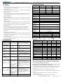
BEIJING EPSOLAR TECHNOLOGY CO., LTD. 7. Protection Tel: +86-10-82894112 / 82894962 9. Technical Specifications PV Reverse Polarity Item Fully protection against PV reverse polarity, no damage to the controller will result. Correct the miswire to resume normal operation. Battery Reverse Polarity Fully protection against battery reverse polarity, no damage to the controller will result. Correct the miswire to resume normal operation. Battery Over Voltage When the battery voltage reaches to the set point of Over Voltage Disconnect Voltage, the controller will stop charging the battery to protect the battery from being over charged to break down. Battery Over Discharge When the battery voltage reaches to the set point of Low Voltage Disconnect Voltage, the controller will stop discharging the battery to protect the battery from being over discharged. Battery Overheating The controller detect the environment temperature through the external temperature sensor. If the environment temperature exceeds 65 ºC, the controller will automatically start the overheating protection to stop working, and recover below 50 ºC. Load Short Circuit Load will be switched off when load short circuit (≥4 times rated current) happens. Controller will automatically attempt to reconnect load for 5 times. If short circuit protection still exist after controller’s 5 times attempts, user have to clear short circuit ,then disconnect and restart the controller or wait for one night-day cycle (night time>3 hours). Damaged Local Temperature Sensor If the temperature sensor short-circuited or damaged, the controller will be charging or Nominal system voltage Rated charge current Max. PV open circuit voltage Battery input voltage range Max. output power Max. output Current Output voltage range Load open circuit voltage Maximum output efficiency Output current control accuracy Battery Type Self-consumption Charge Circuit Voltage Drop Temperature compensation coefficient Communication distance of IR Communication angle of IR Working environment temperature Enclosure Overall dimension LS101240EPLI LS102460EPLI LS2024100EPLI 12VDC 12/24VDC Auto 12/24VDC Auto 10A 10A 20A 30V 50V 50V 9~16V 9~32V 40W 2.6A 30W/12V;60W/24V 2.0A Mounting dimension discharging at the default temperature 25℃ to prevent the battery damaged from PV is protected against small high voltage surge. In lightning prone areas, additional external suppression is recommended. PV array disconnection Battery LED indicator green Fast Flashing Battery over voltage Battery indicator red Battery over discharged Powering on normally, the load is off The dimming function is invalid Parameter settings fail Net weight ≤30mA Sealed(Default) / Gel / Flooded / User ≤9.1mA(12V);≤7.0mA(24V) ≤0.16V -3mV/℃/2V ≤6m ≤15° -35℃~+55℃ IP68(1.5m,72h) 107x68x20mm 108.5x88x25.6 mm 100mm 100.5mm Φ5 PV/BAT:12AWG(4.0mm2) LOAD:18AWG(1.0mm2) 0.23kg Battery charging setting Possible reasons Min.9V can start up the controller. All the LED indicator flashing(battery red indicator flashing) 96% 0.39kg 24V system) No LED indicator Battery Status LED indicator red flashing 60V Battery Voltage Parameters (parameters is in 12V system at 25℃, please use X 2 in 8. Troubleshooting LED Max. Battery Voltage +2V~60V PV/BAT:14AWG(2.5mm2) LOAD: 18AWG(1.0mm2) Power cable High Voltage Transients 9~32V 50W/12V;100W/24V 3.3A Φ4 Mounting hole size overcharging or over discharged. Faults Charging LED indicator off during daytime when sunshine falls on PV modules properly Website:www.epsolarpv.com/www.epever.com Battery Overheating System voltage error ① The connecting wires are error or virtual connection ② Load mode is wrong ③ The controller does not match with the LED light. ④ Output short circuit The controller does not match with the LED light source. This product is a step-up current control, If input voltage is lower than the rated voltage, it is not working. Infrared communication error Troubleshooting Confirm that PV and battery wire connections are correct and tight Measure battery voltage with multi-meter. Min.9V can start up the controller. ① Disconnect the solar array and measure the battery voltage whether is too high; ②Change the controller; ③ Change the battery When the battery voltage is restored to or above setpoint (low voltage reconnect voltage), the load work The controller will automatically stop working. When the temperature is below 50 ºC, the controller will resume to work. Check whether the battery voltage match with the controller working voltage. Please change to a suitable battery or reset the working voltage Over Voltage Disconnect Voltage Charging Limit Voltage Over Voltage Reconnect Voltage Equalize Charging Voltage Boost Charging Voltage Float Charging Voltage Boost Reconnect Charging Voltage Low Voltage Reconnect Voltage Under Voltage Warning Reconnect Voltage Under Voltage Warning Voltage Low Voltage Disconnect Voltage Discharging Limit Voltage Equalize Duration Boost Duration Sealed Gel Flooded User 16.0V 16.0V 16.0V 9~17V 15.0V 15.0V 15.0V 9~17V 15.0V 15.0V 15.0V 9~17V 14.6V 14.4V 13.8V —— 14.2V 13.8V 14.8V 14.6V 13.8V 9~17V 9~17V 9~17V 13.2V 13.2V 13.2V 9~17V 12.6V 12.6V 12.6V 9~17V 12.2V 12.2V 12.2V 9~17V 12.0V 12.0V 12.0V 9~17V 11.1V 11.1V 11.1V 9~17V 10.6V 120min 10.6V —— 10.6V 120min 9~17V 0~180min 120min 120 min 120min 10~180min NOTE: ①Check the connecting cables ②Check the load mode and parameter ③The voltage of LED light source is not in the output voltage range of controller ④Check the connecting cables and LED light source 1) The default battery type is Sealed, For Sealed, Gel, Flooded battery type, the voltage point is fixed, unable to modify it. The adjusting range of equalize duration is 0 to180min and boost duration is 10 to180min. 2) User type is the user defined battery type. The default value is the same as sealed type. When modify it, please follow the below logistic relation: a ) Over Voltage Disconnect Voltage>Charging Limit Voltage ≥Equalize Charging Voltage ≥Boost Charging Voltage ≥ Float Charging Voltage >Boost Reconnect Charging ①Replace the LED light ②Reduce system rated voltage grade and replace the product model For example 24V system change to 12V system, and replace the corresponding controller. See handheld the user device manual Voltage. b ) Over Voltage Disconnect Voltage>Over Voltage Reconnect Voltage. c) Low Voltage Reconnect Voltage>Low Voltage Disconnect Voltage ≥ Discharging Limit Voltage. d ) Under Voltage Warning Reconnect Voltage>Under Voltage Warning Voltage ≥ Discharging Limit Voltage. e ) Boost Reconnect Charging voltage>Low Voltage Disconnect Voltage. Any changes without prior notice! 3 4 Version number:V2.2