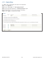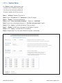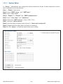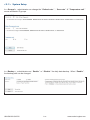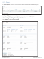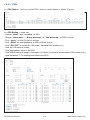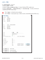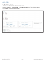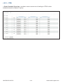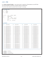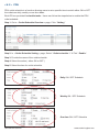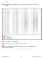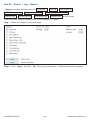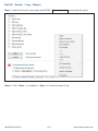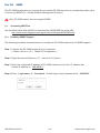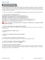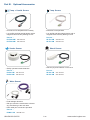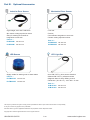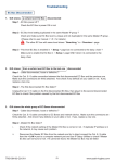
1
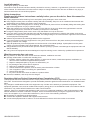
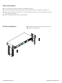
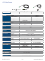
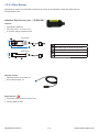
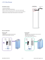
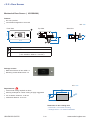
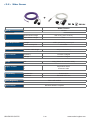
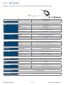
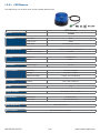
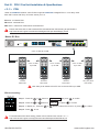
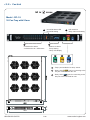
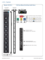
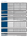
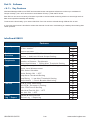
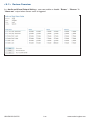
Rack Sensor System
User Manual
IGM-03 Environmental Sensor Management Software
Designed and manufactured by Austin Hughes
UM-IGM-03-Q415V2
www.austin-hughes.com
Legal Information
First English printing, October 2002
Information in this document has been carefully checked for accuracy; however, no guarantee is given to the correctness
of the contents. The information in this document is subject to change without notice. We are not liable for any injury or
loss that results from the use of this equipment.
Safety Instructions
Please read all of these instructions carefully before you use the device. Save this manual for
future reference.
■
■
■
■
■
■
■
■
■
■
■
Unplug equipment before cleaning. Don’t use liquid or spray detergent; use a moist cloth.
Keep equipment away from excessive humidity and heat. Preferably, keep it in an air-conditioned environment with
temperatures not exceeding 40º Celsius (104º Fahrenheit).
When installing, place the equipment on a sturdy, level surface to prevent it from accidentally falling and causing dam
age to other equipment or injury to persons nearby.
When the equipment is in an open position, do not cover, block or in any way obstruct the gap between it and the
power supply. Proper air convection is necessary to keep it from overheating.
Arrange the equipment’s power cord in such a way that others won’t trip or fall over it.
If you are using a power cord that didn’t ship with the equipment, ensure that it is rated for the voltage and current
labelled on the equipment’s electrical ratings label. The voltage rating on the cord should be higher than the one listed
on the equipment’s ratings label.
Observe all precautions and warnings attached to the equipment.
If you don’t intend on using the equipment for a long time, disconnect it from the power outlet to prevent being dam
aged by transient over-voltage.
Keep all liquids away from the equipment to minimize the risk of accidental spillage. Liquid spilled on to the power
supply or on other hardware may cause damage, fire or electrical shock.
Only qualified service personnel should open the chassis. Opening it yourself could damage the equipment and invali
date its warranty.
If any part of the equipment becomes damaged or stops functioning, have it checked by qualified service personnel.
What the warranty does not cover
■
■
■
Any product, on which the serial number has been defaced, modified or removed.
Damage, deterioration or malfunction resulting from:
Accident, misuse, neglect, fire, water, lightning, or other acts of nature, unauthorized product modification, or
failure to follow instructions supplied with the product.
Repair or attempted repair by anyone not authorized by us.
Any damage of the product due to shipment.
Removal or installation of the product.
Causes external to the product, such as electric power fluctuation or failure.
Use of supplies or parts not meeting our specifications.
Normal wear and tear.
Any other causes which does not relate to a product defect.
Removal, installation, and set-up service charges.
□
□
□
□
□
□
□
□
Regulatory Notices Federal Communications Commission (FCC)
This equipment has been tested and found to comply with the limits for a Class B digital device, pursuant to Part 15 of the
FCC rules. These limits are designed to provide reasonable protection against harmful interference in a residential installation.
Any changes or modifications made to this equipment may void the user’s authority to operate this equipment. This
equipment generates, uses, and can radiate radio frequency energy and, if not installed and used in accordance with the
instructions, may cause harmful interference to radio communications.
However, there is no guarantee that interference will not occur in a particular installation. If this equipment does cause
harmful interference to radio or television reception, which can be determined by turning the equipment off and on, the
user is encouraged to try to correct the interference by one or more of the following measures:
■ Re-position or relocate the receiving antenna.
■ Increase the separation between the equipment and receiver.
■ Connect the equipment into an outlet on a circuit different from that to which the receiver is connected.
UM-IGM-03-Q415V2
www.austin-hughes.com
Before Installation
■
■
■
■
It is very important to locate the equipment in a suitable environment.
The surface for placing and fixing the equipment should be stable and level or mounted into a suitable rack.
Make sure the place has good ventilation, is out of direct sunlight, away from sources of excessive dust, dirt, heat,
water, moisture and vibration.
Position the equipment with respect to related facilities.
EC Box Installation
UM-IGM-03-Q415V2
■
■
Suggest the installation at the rear top mounting of rack
M6 screws set not provided.
www.austin-hughes.com
Content
Part I. Hardware
P. 1
< 1.1 > Package Contents
< 1.2 > InfraGuard Features & Specifications
< 1.3 > Daisy Chain Group
< 1.4 > EC Box
< 1.5 > EC Box Level Setting
< 1.6 > EC Box Daisy Chain
Part II. Sensor Installation & Specifications
P. 8
< 2.1 > Overview
< 2.2 > Door Sensor
< 2.3 > Temp. & Humidity Sensor
< 2.4 > Smoke Sensor
< 2.5 > Shock Sensor
< 2.6 > Water Sensor
< 2.7 > LED Light Bar
< 2.8 > LED Beacon
Part III. PDU / Fan Unit Installation & Specifications
P. 21
< 3.1 > PDU
< 3.2 > Fan Unit
UM-IGM-03-Q415V2
www.austin-hughes.com
Content
Part IV. Software
P.29
< 4.1 > Key Features
< 4.2 > Master IP Configuration
< 4.3 > Hardware Requirements of The Management PC
< 4.4 > Supported OS Platform & Language
< 4.5 > Software Download
< 4.6 > First Time Start-up Setting
< 4.7 > Change Port No. of Web Server
Part V. System Setup & Remote Access
P.37
< 5.1 > System Setup
< 5.2 > Remote Access
Part VI. Device Monitoring & Setting
P. 44
< 6.1 > Device Overview
< 6.2 > Sensors
< 6.3 > PDU
< 6.4 > Fan Unit
< 6.5 > Door
Part VII. Events / Log / Report
P. 57
Part VIII. SNMP
P. 64
Part IX. FAQ
P. 66
Part X. Troubleshooting
P. 68
Part XI. Optional Accessories
P. 72
UM-IGM-03-Q415V2
www.austin-hughes.com
Part I. Hardware
< 1.1 > Package Contents
Unpacking
The equipment comes with the standard parts shown on the package contents. Check and make sure they are included and in good
condition. If anything is missing, or damage, contact the supplier immediately.
- EC-300M Master EC Box x 1
EC-300 Slave EC Box x 1
OR
- 6’ Power cord x 1
- 6’ Power cord x 1
< 1.2 > InfraGuard Features & Specifications
EC-300M
EC-300
( Master Box )
( Slave Box )
1st Level
2nd - 16th Level
via Master Box
Temp-Humid Sensor
2
2
Smoke / Shock Sensor
2
2
Water Sensor
2
2
Door Sensor
4
4
LED Light Bar
2
2
LED Flashing Beacon
1
1
Alarm Board
1
1
Integrated PDU
4 ( daisy chain )
4 ( daisy chain )
Integrated Fan Unit
4 ( daisy chain )
4 ( daisy chain )
Product Dimension ( W x D x H )
400 x 135 x 39.7 mm / 15.7 x 5.3 x 1.6 inch
Packing Dimension ( W x D x H )
557 x 367 x 98 mm
Net Weight
1.06 kgs / 2.3 lbs
Gross Weight
2.2 kgs
Power Consumption
Auto-sensing 100 to 240VAC, 50 / 60Hz, Max. 48 Watt
Operating Temperature
0 to 55ºC Degree
Storage Temperature
-5 to 60ºC Degree
Relative Humidity
5~90%, non-condensing
Mounting
1U Rackmount
Safety Regulatory
FCC & CE certified
Environmental
RoHS & REACH compliant
Daisy Chain
SNMP
LAN Port
Daisy Chain Port - LINK
Daisy Chain Port - OUT
Dual Power Input Option
Temperature LED
UM-IGM-03-Q415V2
P.1
/ 21.9 x 14.4 x 3.9 inch
/ 4.8 lbs
www.austin-hughes.com
< 1.3 > Daisy Chain Group
EC 300M as the 1st level master EC box
The EC box can be cascaded up to 16 levels
Only 1 x IP for 16 x EC box remote access
Daisy chain by Cat5/6 cable
Max. distance between 2 EC box is 20M
Max. distance in a daisy chain group up to 300M
One InfraGuard network can expand up to 30 daisy chain groups ( master IP group ).
Each daisy chain group supports up to 16 EC Boxes
Each InfraGuard network can monitor 480 EC Boxes
Each EC Box supports PDU x 4 & fan unit x 4
Up to 1920 PDUs & 1920 fan units can be installed under one InfraGuard network
UM-IGM-03-Q415V2
P.2
www.austin-hughes.com
< 1.3 > Installation Diagram
One Box One Rack
Front Door
5
3
4
1
6
2
7
8
9
10
Item
Qty.
Location
1
EC Box
1
rackmount on rear top
2
LED Light Bar
2
front & rear top inside
3
Smoke Sensor
1
rear inside top
4
Door Sensor
2
top corner of door
5
Flashing LED Beacon
1
front rack roof
6
Temp. & Humid. Sensor
2
any inside position
7
Shock Sensor
1
upper inside
8
Fan Unit
4
door mount or rackmount
9
PDU
4
vertical or rackmount
10
Water Sensor
1
surrounding rack on floor
UM-IGM-03-Q415V2
P.3
www.austin-hughes.com
< 1.3 > Installation Diagram
One Box Two Racks
Front Door
Front Door
5
3
4
4
1
3
6
6
2
2
7
8
8
9
7
9
10
10
Rack 2
Rack 1
* either smoke sensor or shock sensor
Item
Rack 1
Rack 2
1
EC Box
1
-
2
LED Light Bar
1
1
3
Smoke Sensor
1
4
Door Sensor
2
2
5
Flashing LED Beacon
1
-
6
Temp. & Humid. Sensor
1
1
7
Shock Sensor
1
8
Fan Unit
2
2
9
PDU
2
2
10
Water Sensor
1
1
UM-IGM-03-Q415V2
*
*
P.4
1
1
*
*
www.austin-hughes.com
< 1.4 > EC Box
EC-300M, Master Box
6
( 1st level )
7
Power
8
9
Smoke / Shock
1 - Lamp - 2
10
11
Beacon
Door
1
2
3
4
ON
Alarm
DIP
12VDC
T1
1
2
T2
1
2
3
4
5
6
7
8
LAN
Out
Box Level
3
4
5
T1
T2
12
PDU
Fan
1 - Water - 2
13
14
15
1
Power input
6
Temp. LED display x 2
2
Dual power input ( option )
7
Door sensor port x 4
8
Smoke / Shock sensor port x 2
9
LED Light Bar port x 2
3
LAN port ( RJ-45 connect to network device )
4
OUT port ( RJ-45 connect to level 2nd slave EC box )
10
Port for 3rd party alarm board x 1
5
Dip switch ( level setting )
11
LED beacon port x 1
12
Temp. & Humid. sensor port x 2
PDU port x 1
13
( RJ-45, up to PDU daisy chain level x 4 )
Fan unit port x 1
14
( RJ-45, up to fan unit daisy chain level x 4 )
Water sensor port x 2
15
EC-300, Slave Box
( From 2nd - 16th level )
Power
Door
Beacon
1
2
3
4
ON
Smoke / Shock
1 - Lamp - 2
Alarm
DIP
12VDC
T1
T2
1
Link
Out
2
3
4
5
6
7
8
Box Level
16
T1
T2
PDU
Fan
1 - Water - 2
Only for Slave EC Box
16
Link & Out port
( RJ-45 for daisy chain connection )
UM-IGM-03-Q415V2
P.5
www.austin-hughes.com
< 1.5 > EC Box Level Setting
Steps :
■
■
■
■
Only Master EC Box built-in IP remote access module.
Master EC Box MUST be set on the 1st daisy chain level according to the table below.
For the 2nd - 16th levels ( slave EC box ), please make the level setting according to the table below.
For the cabling connection, please refer to the next page.
ON
OFF
Daisy chain level setting
Using the
dip switch no. 1, 2, 3, & 4
to setup each EC box level level as below :
Cascaded EC boxes
1st level Master EC box
2nd level Slave EC box
3rd level Slave EC box
4th level Slave EC box
5th level Slave EC box
6th level Slave EC box
7th level Slave EC box
8th level Slave EC box
9th level Slave EC box
10th level Slave EC box
11th level Slave EC box
12th level Slave EC box
13th level Slave EC box
14th level Slave EC box
15th level Slave EC box
16th level Slave EC box
1
On
Off
On
Off
On
Off
On
Off
On
Off
On
Off
On
Off
On
Off
2
On
On
Off
Off
On
On
Off
Off
On
On
Off
Off
On
On
Off
Off
3
On
On
On
On
Off
Off
Off
Off
On
On
On
On
Off
Off
Off
Off
Dip switch no.
4
5
On
Off
On
Off
On
Off
On
Off
On
Off
On
Off
On
Off
On
Off
Off
Off
Off
Off
Off
Off
Off
Off
Off
Off
Off
Off
Off
Off
Off
Off
6
Off
Off
Off
Off
Off
Off
Off
Off
Off
Off
Off
Off
Off
Off
Off
Off
7
Off
Off
Off
Off
Off
Off
Off
Off
Off
Off
Off
Off
Off
Off
Off
Off
8
Off
Off
Off
Off
Off
Off
Off
Off
Off
Off
Off
Off
Off
Off
Off
Off
** No. 5, 6, 7 & 8 dip switch reserved
UM-IGM-03-Q415V2
P.6
www.austin-hughes.com
< 1.6 > EC Box Daisy Chain
Remarks :
■
■
■
■
■
Each Master IP group supports 16 daisy chain levels.
The 1st level EC box must be Master EC box.
1 x Master EC box allows access to 16 levels.
For remote access of EC boxes, simply connect 1 x Master EC box.
The 2nd - 16th level EC boxes must be slave EC box.
1st level
Master EC box
LAN
2nd level
Slave EC box
OUT
LINK
Cat5 / 6 cable
max. 20 meters
3rd level
Slave EC box
OUT
LINK OUT
Cat5 / 6 cable
max. 20 meters
Max. distance in a daisy chain group up to 300M
To LINK port of next
level slave EC box
(max level: 16)
To Network Device
for IP Access via WAN
UM-IGM-03-Q415V2
P.7
www.austin-hughes.com
Part II. Sensor Installation & Specifications
< 2.1 > Overview
EC Box
Power
Door
Beacon
1
2
3
4
ON
Smoke / Shock
1 - Lamp - 2
Alarm
DIP
12VDC
T1
T2
1
LAN
UM-IGM-03-Q415V2
Out
P.8
2
3
4
5
6
7
Box Level
8
T1
T2
PDU
Fan
1 - Water - 2
www.austin-hughes.com
< 2.1 > Overview
Door
Sensor
LED Beacon
LED Light Bar
Smoke
Sensor
EC Box
TH
Sensor
Shock
Sensor
Water
Sensor
UM-IGM-03-Q415V2
P.9
www.austin-hughes.com
< 2.2 > Door Sensor
Inductive Door Sensor
Mechanical Door Sensor
IG-DSI-2M
IG-DSW-2M
3.00 mm
Operating Force
/
/
/
Sensing distance
Max. 3mm
/
/
Part no.
Sensitivity
Actuation
Travelling Distance
Sensing object
Power Requirement
Voltage
100mA
Plastic
Color
Black
Cable Length
Environmental
Operating
Storage
/
/
12VDC, powered by sensor port
Material
Connection
sensor w/ 2m cable ( standard )
sensor w/ 4m cable ( option )
-20 to 60°C Degree
-20 to 60°C Degree
Relative Humidity
Dimensions
3.5±1 N
Ferrous metal
Current Consumption
Housing
9.25 mm
-30 to 70°C Degree
5~90%, non-condensing
Product
32.5L x 12.2W x 9.2H mm
52W x 22.5L mm
( with metal plate )
Packing
/
/
6g
14g ( with metal plate )
Weight
Net / Gross
Supply includes
1
Inductive door sensor
with 2m cable
Mechanical door sensor
2
2mm Adhesive tape
Metal plate
3
/
2m cable
InfraGuard only
Compatibility
FCC & CE certified
Safety Regulatory
Environmental
UM-IGM-03-Q415V2
RoHS2 & REACH compliant
P.10
www.austin-hughes.com
< 2.2 > Door Sensor
Optional door sensor is an essential accessories as users can be alerted by visual and audio alarm for
unauthorized access.
Inductive Door Sensor, pair ( IG-DSI-2M )
Features
light weight / adhesive
mini size ( 32.5 x 12.2 x 9.2 mm )
no custom cutting required on door
Front View
12.2 mm
2
1
32.5 mm
3
4
9.2 mm
Side View
1
Sensor area
2
Red LED ( light up while door opening )
3
2m cable
4
Cable jack ( connect to EC box )
5
2mm adhesive tape
5
Package content
Inductive sensor w/ 2m cable x 2
2mm adhesive tape x 6
Requirements
rack frame made of ferrous metal ( iron )
sensing distance 3mm
UM-IGM-03-Q415V2
P.11
www.austin-hughes.com
< 2.2 > Door Sensor
Suggested
sensor position
Installation steps
to EC box
- connect to the EC box
- guide & fix the cable with cable clips
- place the sensor at the top of the door, close to the opening side
- adjust the sensor with adhesive tape to ensure the sensing distance
between door to frame within 3mm while door in close status
Sensor Operation
DOOR OPEN
- open door
- inductive sensor lose detection with rack frame
- Red LED of sensor light up
- DOOR OPEN SIGNAL sends out
DOOR CLOSE
- close door
- inductive sensor detects the rack frame
- DOOR CLOSE SIGNAL sends out
Door
frame
Rack
frame
Door
frame
CLOSED
Rack
frame
OPENED
Sensing distance
< 3mm
UM-IGM-03-Q415V2
Sensing distance
> 3mm
P.12
www.austin-hughes.com
< 2.2 > Door Sensor
Mechanical Door Sensor ( IG-DSW-2M )
Features
low cost / precise
cost efficient integration to new rack
Front View
unit : mm
Top View
1
Side View
11
7.3
22.5
3
15.0
2
3
1
Steel mounting plate with 2 screw holes
2
Cable connector
3
Press button ( total travel distance : 9.25 mm
15.75
6.5
52.0
9.25
)
( min. actuation distance : 3.00 mm )
Package content
Mechanical sensor w/ 2m cable x 2
Mounting screws 6#32x4.5mm x 2
unit : mm
Requirements
37.5
custom hole cutting required on doors
23
ordering a sample for custom cutting is highly suggested
2-
12.5
6.3
min. actuation distance : 3.00 mm
total travel distance : 9.25 mm
3 .5
Dimension of door cutting hole
- circle hole x 2 for screw mounting
- rectangle hole x 1 for sensor installation
UM-IGM-03-Q415V2
P.13
www.austin-hughes.com
< 2.2 > Door Sensor
Suggested
sensor position
Installation steps
to EC box
- connect to the EC box
- place the sensor at the top middle of the door
- install the sensor in the custom hole
- secure it with bundled mounting screws 6#32x4.5mm x 2
Sensor Operation
DOOR CLOSE
- close door
- Sensor button is pressed on
DOOR OPEN
- open door
- Sensor button is released
- DOOR CLOSE SIGNAL sends out
- DOOR OPEN SIGNAL sends out
Door
frame
Door
frame
Rack
frame
Rack
frame
OPENED
CLOSED
Button released
Actuation distance > 3mm
Physical touch required
UM-IGM-03-Q415V2
P.14
www.austin-hughes.com
< 2.3 >
Temp. & Humidity Sensor
Each EC box provides Temp. & Humid. Sensor port x 2. If more TH sensors required, two temp. & humid. sensor ports
on each integrated PDU can be applied.
Part no.
Temperature
Sensitivity
Temp. & Humid. Sensor
Temp. Sensor
IG-TH01
IG-T01
Range
Accuracy
0 to 80°C ( 32 to 176°F )
±0.5°C typical ( ±1°F )
Resolution
0.1°C ( 0.2°F )
Response Time
Relative
Humidity
Sensitivity
Range
Accuracy
Resolution
Response Time
Power
Requirement
5 to 30 sec
0 to 100% R.H
/
0 to 100, ±8.0% R.H
20 to 80, ±4.5% R.H.
/
1% R.H.
/
8 sec
/
Voltage
12VDC, powered by sensor port
Current Consumption
20mA
Power consumption
0.24 Watt
Power on indicator
Housing
Red
Green
Chassis & Cover
Plastic
Color
Dark gray
Installation
Connection
Cable Length
Magnetic base for unrestricted installation
TH sensor w/ 2m cable ( standard )
TH sensor w/ 4m cable ( option )
Cable Specification
Cable Color
±1°C ( ±2°F)
T sensor w/ 2m cable ( standard )
T sensor w/ 4m cable ( option )
4-wired 3.5mm to RJ11
Black
Beige
Operating
0 to 80°C Degree
Storage
-5 to 80°C Degree
Humidity
0~100%, non-condensing
Dimensions
Product
30L x 25W x 18H mm
Weight
Net
Supply includes
1
TH Sensor
2
4-wired 3.5mm to RJ11 cable ( 2m, black color )
Environmental
Compatibility
66g
InfraPower
W / WS / Wi / WSi series PDU
InfraSolution
X-2000 series
InfraGuard
Safety Regulatory
Environmental
UM-IGM-03-Q415V2
Temperature Sensor
EC-300M & EC-300
FCC & CE certified
RoHS2 & REACH compliant
P.15
www.austin-hughes.com
< 2.4 >
Smoke Sensor
Smoke sensor comes with a RED LED. When smoke alarm triggers, the RED LED lights on with beep sound continuously.
Smoke Sensor
Part no.
IG-S01
Sensitivity
Smoke sensitivity
0.15 ~ 0.3 dB/m
Alarm Output
Solid State Relay
24VDC@1A
Alarm LED
Red
Audio Alarm
80 dB
Continuous beeps
Audio Alarm Pattern
Power Requirement
Voltage
12VDC, powered by sensor port
Current Consumption
200uA
Power ON LED
Housing
Red LED flashes every 6 seconds
Chassis & Cover
ABS plastic
Color
Ivory White
Connection
Cable Length
1m / 3m ( option )
Environmental
Operating
-5 to 50°C Degree
Storage
-10 to 60°C Degree
Humidity
5~90%, non-condensing
Dimensions
Product
103L x 103W x 55H mm
Weight
Net
Supply includes
1
Compatibility:
InfraSolution
165g
Smoke Sensor with 1m cable
X-2000 series
InfraGuard
EC-300M & EC-300
FCC & CE certified
Safety Regulatory
Environmental
UM-IGM-03-Q415V2
RoHS2 & REACH compliant
P.16
www.austin-hughes.com
< 2.5 >
Shock Sensor
Shock sensor comes with a RED LED. When shock alarm triggers, the RED LED lights on continuously.
Shock Sensor
Part no.
Sensitivity
IG-V01
Detection radius
3.5 m
Adjustable sensitivity
Alarm Output
Internal micro knob with screwdriver cross slot
Solid State Relay
12VDC@100mA
Alarm hold time
Approx. 2.0 sec.
Alarm LED
Power Requirement
Red
Voltage
12VDC, powered by sensor port
Current Consumption
15mA
Power consumption
Housing
0.18 Watt
Chassis & Cover
ABS plastic
Color
White
Connection
Cable Length
1m / 3m ( option )
Environmental
Operating
-5 to 55°C Degree
Storage
-10 to 60°C Degree
Humidity
5~90%, non-condensing
Dimensions
Product
26 x 85 x 24 mm
Weight
Net
Supply includes
1
Compatibility
InfraSolution
40g
Shock Sensor with 1m cable
X-2000 series
InfraGuard
EC-300M & EC-300
FCC & CE certified
Safety Regulatory
Environmental
UM-IGM-03-Q415V2
RoHS2 & REACH compliant
P.17
www.austin-hughes.com
< 2.6 > Water Sensor
+
Water Sensor
IG-W01
Part no.
Power Requirement
Measurement Range
Wet or Dry (-20°C to 60°C)
Rope Sensor Length
5m
Voltage
5VDC, powered by sensor port
Power consumption
125 mWatt
Connection
Extension cable length
3m ( non-detection )
Environmental
Operating
-20 to 60°C Degree
Storage
-20 to 80°C Degree
Weight
Net
Supply includes
1
Rope water sensor
2
Extension cable
Compatibility
450g ( Sensor & extension cable )
InfraSolution
X-2000 series
InfraGuard
EC-300M & EC-300
FCC & CE certified
Safety Regulatory
Environmental
UM-IGM-03-Q415V2
RoHS2 & REACH compliant
P.18
www.austin-hughes.com
< 2.7 > LED Light Bar
LED light bar can be ON / OFF by door sensor OR always ON by IGM-03 management software setting.
LED Light Bar
Part no.
Light
Power Requirement
Housing
CLB-IX-002
Color
Cool White
Output
250 Lumens
Color Temperature
5600-7000K
Number of LED
18 High Output CREE SMD LED
Life Expectancy
30,000 hrs
Voltage
12VDC, powered by sensor port
Current Consumption
0.375A
Power consumption
4.5 Watt
Chassis
Extruded aluminum with silver powder coat
Diffuser
Acrylic with milky white
Magnetic base for unrestricted installation
Installation
Connection
Cable Length
2m / 3m ( option )
Environmental
Operating
-20 to 50°C Degree
Storage
-20 to 60°C Degree
Relative Humidity
Dimensions
Product
Weight
Net
Compatibility
InfraSolution
5~90%, non-condensing
300L x 20W x 12H mm
84g
X-2000 series
InfraGuard
EC-300M & EC-300
FCC & CE certified
Safety Regulatory
Environmental
UM-IGM-03-Q415V2
RoHS2 & REACH compliant
P.19
www.austin-hughes.com
< 2.8 > LED Beacon
The LED Beacon can be stuck firmly by the bundled adhesive tape.
LED Beacon
Part no.
Notification
IG-FB03
Len Color
Blue
Light Source
White
Flash Rate
Power Requirement
120 flashes per minute
Voltage
12VDC, powered by sensor port
Current Consumption
Housing
0.175A
Cover Len
Polycarbonate
Color
Blue
Connection
Cable Length
Environmental
Operating
-20 to 50°C Degree
Storage
-20 to 60°C Degree
1m / 3m
Relative Humidity
Dimensions
Product
Weight
Net
Supply includes
1
Compatibility
InfraSolution
5~90%, non-condensing
72L x 72W x 45H mm
50g
LED Beacon with 1m cable
X-2000 series
InfraGuard
EC-300M & EC-300
FCC & CE certified
Safety Regulatory
Environmental
UM-IGM-03-Q415V2
RoHS2 & REACH compliant
P.20
www.austin-hughes.com
Part III. PDU / Fan Unit Installation & Specifications
< 3.1 > PDU
Under an InfraGuard network, each EC Box supports InfraPower intelligent PDU x 4 in a daisy chain.
Each PDU comes with Temp. & Humid. sensor port x 2
W series : monitored PDU
WS series : switched PDU
WSi series : outlet level measurement switched PDU
Please visit below link to select desired PDU & download the PDU drawing & specifications.
http://www.austin-hughes.com/solutions/intelligent-kWh-pdu.html#Single_Phase
Master EC Box
Power
Beacon
Door
1
2
3
Smoke / Shock
4
ON
1 - Lamp - 2
Alarm
DIP
12VDC
T1
T2
1
LAN
Out
2
3
4
5
6
7
8
Box Level
T1
T2
PDU
Fan
1 - Water - 2
Cat 5 / 6 cable Up to 20M
Cat 5 / 6 cable
Up to 20M
Cat 5 / 6 cable
Up to 20M
Cat 5 / 6 cable
Up to 20M
4
1st level
PDU meter
2nd level
PDU meter
3rd level
PDU meter
4th ( last ) level
PDU meter
Max. daisy chain distance from EC box to the 4th PDU up to 80M
PDU level setting :
Step 1 - Press the
&
button to
display no.9
Step 2 - Press the
&
button to
PDU ID
Step 3 - In display 9.1, Press the
Step 4 - Press
&
and press
and press
to confirm
to confirm
button to select PDU level no. & press
to confirm
to exit
For details about PDU level setting, please refer to IPM-03 user manual < 3.1 > :
http://www.austin-hughes.com/support/usermanual/infrapower/UM-IPM-03.pdf
UM-IGM-03-Q415V2
P.21
www.austin-hughes.com
< 3.2 > Fan Unit
Under an InfraGuard network, each EC Box supports InfraCool remote fan unit x 4 in a daisy chain.
Each fan unit comes with TEMP. sensor port x 1
Master EC Box
Power
Door
Beacon
1
2
3
4
ON
Smoke / Shock
1 - Lamp - 2
Alarm
DIP
12VDC
T1
T2
1
LAN
Out
1st level
Fan unit model
LINK
OUT
2
3
4
5
6
7
8
Box Level
2nd level
Fan unit model
Cat 5 / 6 cable
Up to 20M
LINK
OUT
T1
T2
PDU
Fan
1 - Water - 2
3rd level
Fan unit model
Cat 5 / 6 cable
Up to 20M
LINK
OUT
Cat 5 / 6 cable
Up to 20M
Max. daisy chain distance from EC box to the 4th fan unit up to 80M
LINK
OUT
4th ( last ) level
Fan unit model
UM-IGM-03-Q415V2
P.22
www.austin-hughes.com
< 3.2 > Fan Unit
ON
OFF
Fan unit level setting :
Using the
dip switch no. 1, 2, 3, 4, 5, 6 & 8
to setup each FAN unit level as below :
Cascaded FAN units
1st level Fan Unit Model
2nd level Fan Unit Model
3rd level Fan Unit Model
4th level Fan Unit Model
1
On
Off
On
Off
2
On
On
Off
Off
Dip switch no.
3
4
5
On
On
On
On
On
On
On
On
On
On
On
On
6
On
On
On
On
8
Off
Off
Off
Off
** No. 7 dip switch only for audio alarm setting
Using the
dip switch no. 7
to setup each FAN unit audio alarm as below :
Dip switch 7
On
Off
Enable
Disable
If enable the audio alarm, the buzzer will sound when the outside temperature is over the preset alarm
temperature.
UM-IGM-03-Q415V2
P.23
www.austin-hughes.com
< 3.2 > Fan Unit
Model : RF-1.3
1U Fan Tray with 3 fans
2
- Unit CFM Status LED
- Unit CFM Setting
1
- Individual fan status
- Individual fan On /
Off buttons
4
- DIP switch for
daisy chain level setting
3
- Buttons for Alarm
Temp. Setting
- Temp. LED display
5
6
7
TEMP
LINK
OUT
5
- Temp. port bundled w/ a temp. sensor
6
- Daisy chain LINK
LIN K port for connecting to the
out port of the last level fan unit
7
- Daisy chain OUT
OU T port for connecting to the
link port of the next level fan unit
43.5
463
UM-IGM-03-Q415V2
P.24
www.austin-hughes.com
< 3.2 > Fan Unit
Model : RF-1.6
1U Fan Tray with 6 fans
2
- Unit CFM Status LED
- Unit CFM Setting
1
4
- DIP switch for
daisy chain level setting
3
- Individual fan status
- Individual fan On / Off buttons
- Buttons for Alarm
Temp. Setting
- Temp. LED display
5
6
7
TEMP
LINK
OUT
5
- Temp. port bundled w/ a temp. sensor
6
- Daisy chain LINK
LIN K port for connecting to the
out port of the last level fan unit
7
- Daisy chain OUT
OU T port for connecting to the
link port of the next level fan unit
43.5
463
UM-IGM-03-Q415V2
P.25
www.austin-hughes.com
< 3.2 > Fan Unit
Model : RF-1.9
1U Fan Tray with 9 fans
2
- Unit CFM Status LED
- Unit CFM Setting
1
4
- DIP switch for
daisy chain level setting
3
- Individual fan status
- Individual fan On / Off buttons
- Buttons for Alarm
Temp. Setting
- Temp. LED display
5
6
7
TEMP
LINK
OUT
5
- Temp. port bundled w/ a temp. sensor
6
- Daisy chain LINK
LIN K port for connecting to the
out port of the last level fan unit
7
- Daisy chain OUT
OU T port for connecting to the
link port of the next level fan unit
43.5
463
UM-IGM-03-Q415V2
P.26
www.austin-hughes.com
< 3.2 > Fan Unit
Model : RF-33.9
33U Door Mount Fan Panel with 9 fans
Front View
Side View
195 mm
42.9 mm
195 mm
4
TEMP
5
LINK
6
OUT
7
4
- DIP switch for daisy chain level setting
5
- Temp. port bundled w/ a temp. sensor
6
- Daisy chain LINK
LIN K port for connecting
to the out port of the last level fan unit
7
- Daisy chain OUT
OU T port for connecting
to the link port of the next level fan unit
1466 mm
UM-IGM-03-Q415V2
P.27
1
- Individual fan status
- Individual fan On / Off buttons
2
- Unit CFM Status LED
- Unit CFM ( fan speed ) Setting
3
- Buttons for Alarm Temp. Setting
www.austin-hughes.com
< 3.2 > Fan Unit
Remote Fan
Model
RF-1.3 / 1.6 / 1.9
RF-33.9
No. of Fan
3 / 6 / 9
9
Mounting
1U
Door mount
CFM Level
Normal / High / Max.
Individual Fan ON / OFF
Yes
Individual Fan CFM
Unit CFM ( Approximately )
108 CFM
324 / 648 / 972 CFM
IP Remote Access
Not available, must be via Master IP fan on the 1st level
Daisy Chain Level
2nd to 16th level
MTBF
Temperature
Sensor
Power
50,000 hrs
Temperature Port
1 x temperature sensor port ( sensor bundled )
Measurement Range
0 to 99.9°C
Measurement Accuracy
+/- 1.5%
Temperature Alarm
Yes
Input
100V or 240V AC at 50 or 60Hz via IEC type cord
Consumption
Environmental
Conditions
Dimensions
Weight
Operating
20W / 40W / 60W
UM-IGM-03-Q415V2
60W
0 to 50°C
Storage
-5 to 60°C
Relative Humidity
90%, non-condensing
Shock
50G peak acceleration ( 11ms, half-sine wave )
Vibration
58~100Hz / 0.98G ( 11ms / cycle )
Model
Product Dimension
Packing Dimension
RF-1.3
480 x 298.3 x 43.5 mm
18.9 x 11.7 x 1.71 inch
380 x 535 x 120 mm
15 x 21.1 x 4.7 inch
RF-1.6
480 x 458.3 x 43.5 mm
18.9 x 18 x 1.71 inch
550 x 550 x 120 mm
21.7 x 21.7 x 4.7 inch
RF-1.9
480 x 623.3 x 43.5 mm
18.9 x 24.5 x 1.71 inch
550 x 730 x 120 mm
21.7 x 28.7 x 4.7 inch
RF-33.9
195 x 42.9 x 1466 mm
7.7 x 1.7 x 57.7 inch
263 x 106 x 1650 mm
10.4 x 4.2 x 65.0 inch
Model
Net Weight
Gross Weight
RF-1.3
4 kgs / 8.8 lbs
5 kgs / 11 lbs
RF-1.6
6.8 kgs / 15 lbs
8 kgs / 17.6 lbs
RF-1.9
9 kgs / 19.8 lbs
11 kgs / 24.2 lbs
RF-33.9
5 kgs / 11 lbs
7.4 kgs / 16.3 lbs
FCC & CE certified
Regulatory
Environmental
972 CFM
RoHS2 & REACH compliant
P.28
www.austin-hughes.com
Part IV. Software
< 4.1 > Key Features
InfraGuard Manager IGM-03 is a FREE environmental sensor management software to monitor up to 30 Master IP
Groups remotely ( max. 16 EC box levels in each Master IP Group ), total 480 EC boxes.
Each EC box can connect a variety of sensors to provide an environmental monitoring solution to secure high levels of
data center operational stability and flexibility.
To enhance the functionality, up to 1920 x kWh PDU / Fan Unit can be monitored through IGM-03 GUI as well.
5 concurrent user license is bundled to achieve the demand of multi-user / multi-tasking in nowadays’ time sharing data
center operation.
InfraGuard IGM-03
Features
Capacity
Master IP Group ( Just 1 IP for 16 EC box levels )
EC box number
Concurrent user
Device
Overview
Status of Sensor, PDU, Fan Unit & Door
Sensor
Peripherals
Status Monitoring
30
480
5
Device / Audio and Visual Output Setting
Location of Sensor / Peripherals
Temp-Humid Alarm / Rising Alert Threshold Setting
PDU
Energy Consumption kWh / Amp Monitoring
Outlet Level Measurement
PDU Outlet Schedule
Outlet Switch ON / OFF
Amp Alarm Threshold Setting
Amp Rising / Low Alert Threshold Setting
Temp-Humid / Circuit Breaker Monitoring
Fan Unit
CFM & Temp. Monitoring
Unit CFM ( fan speed ) Setting
Auto CFM Control Setting
Individual Fan Kit ON / OFF
Fan Unit ON / OFF
Event
Log / Report
UM-IGM-03-Q415V2
System & Device Event
Device Log / Reporting
P.29
www.austin-hughes.com
< 4.2 > Master IP Configuration
Please take the following steps to configure the Master EC box.
Step 1. Prepare a notebook computer to download the IP setup utilities from the link :
http://www.austin-hughes.com/support/utilities/infraguard/MasterIPsetup.msi
Step 2. Double Click the MasterIPsetup.msi
and follow the instruction to complete the installation
Step 3. Go to each Master EC box with the notebook computer & a piece of CAT. 5 / 6 cable to set up the IP configuration
by IP setup utilities as below. Please take the procedures for all Master EC box ONE BY ONE
Master EC box
EC-300M
CAT. 5 / 6 cable
To notebook computer
LAN port
To LAN port
Ensure the Master EC box in
power ON status
Reconnect the Master EC box with the network device
( router or hub ), after finish master IP configuration.
Write down the new IP address & password
for < Setup > purpose, refer to P.40
Step 4. Click “ Scan ” to search the Master EC box
Step 5. Enter device name in “ Name ” ( min. 4 char. / max. 16 char. ). Default is “ Name ”
Step 6. Enter device location in “ Location “ ( min. 4 char. / max. 16 char. ). Default is “ Rack_001 ”
Step 7. Enter password in “ Password “ for authentication ( min. 8 char. / max. 16 char. ). Default is “ 00000000 ”
Step 8. Enter new password in “ New password ” ( min. 8 char. / max. 16 char. ).
Step 9. Re-enter new password in “ Confirm new password ”
Step 10. Change the desired “ IP address ” / “ Subnet mask ” / “ Gateway ”, then Click “ Save ” to confirm the changes
The default IP setting is as below:
IP address:
192.168.0.1
Subnet mask:
255.255.255.0
Gateway:
192.168.0.254
UM-IGM-03-Q415V2
P.30
www.austin-hughes.com
< 4.3 > Hardware Requirements of The Management PC
Please prepare a management PC with the hardware requirements as below for
InfraGuard Manager - IGM-03
Recommended hardware requirements :
- Processor :
Dual Core 2GHz or above
- Memory :
2GB RAM
- Available Disk Space :
500GB
- Display :
1440 x 900 or higher resolution monitor
- The default service port of web server is 80.
- A dedicated PC to run InfraGuard Manager - IGM-03 is recommended.
- Make sure the management PC is POWER ON & IGM-03 is under operation.
Otherwise, daily data backup will NOT be proceeded.
UM-IGM-03-Q415V2
P.31
www.austin-hughes.com
< 4.4 > Supported OS Platform & Language
InfraGuard Manager – IGM-03 supports the OS platforms & languages as below:
- MS Windows 7 Professional with SP1 ( English Edition )
- MS Windows 7 Ultimate with SP1 ( English Edition )
- MS Windows 8 Professional (32bit & 64bit, English edition only)
- MS Windows Server 2003 R2 Standard Edition with SP2 ( English Edition )
- MS Windows Server 2008 Standard Edition SP2 ( English Edition )
- MS Windows Server 2008 R2 Standard Edition SP1 ( English Edition )
Make sure users login the management PC as a member of “ Administrator “ Group
before IGM-03 installation & execution
User can select the following languages under Control Panel > Region and Language in English Edition OS:
1) Arabic (Saudi Arabia)
2) Chinese (Traditional, Hong Kong S.A.R.)
3) Dutch (Netherlands)
4) English (Australia)
5) English (United Kingdom)
6) English (United States)
7) French (France)
8) German (Germany)
9) German (Switzerland)
10) Italian (Italy)
11) Japanese (Japan)
12) Korean (Korea)
13) Norwegian (Norway)
14) Portuguese (Portugal)
15) Russian (Russia)
16) Spanish (Spain)
17) Turkish (Turkey)
UM-IGM-03-Q415V2
P.32
www.austin-hughes.com
< 4.5 > Software Download
Software download
Please download the InfraGuard Manager - IGM-03 to the management PC
from the link http://www.austin-hughes.com/support/software/infraguard/IGM-03.msi
Double click the
IGM-03.msi
and follow the instruction to complete the installation.
IGM-03.msi
click “ Next ”
click “ Install ”
click “ Finish ”
Complete
UM-IGM-03-Q415V2
P.33
www.austin-hughes.com
< 4.6 > First Time Start-up Setting
Step 1. Double Click InfraGuard Manager - IGM-03 and
follow the instruction to complete start-up setting.
IGM-03
InfraGuard Manager
For MS Windows 7 and MS Windows server 2008,
it requires to run a program with administrator rights before execution:
- Right click InfraGuard Manager - IGM-03 , and then select Properties.
- Click the Compatibility tab.
- Tick the box Run this program as an administrator, and then click OK.
UM-IGM-03-Q415V2
P.34
www.austin-hughes.com
< 4.6 > First Time Start-up Setting
Step 2. Click “ Next ” in “ InfraGuard Manager start-up setting ” box
Step 3. Input the fields of the following window & Click “ Install ”
If the port of web server
is not 80, please input the
appropriate no. here and
follow the instruction in “
Change port no. of web
server“ next page to make
the change effective.
PostgreSQL password can be changed by user.
The password MUST contain at least three of the following four character groups:
- English uppercase characters ( A through Z )
- English lowercase characters ( a through z )
- Numerals ( 0 through 9 )
- Non-alphabetic characters ( such as !, $, #, % )
Complete
UM-IGM-03-Q415V2
P.35
www.austin-hughes.com
< 4.7 > Change Port no. of Web Server
If users want to use another port no. instead of 80, please take the following steps after
InfraGuard Manager IGM-03 “ First time start-up setting ” is completed.
Step 1. Go to the path of web server being installed. ( Default: C:\AppServ\Apache2.2\conf\ )
Step 2. Open “ httpd.conf ” & change “ Listen 80 ” to “ Listen xx ” where xx means the port
users want to use save the change
Step 3. Restart Apache services.
Go to Control Panel > Administrative Tools > Services > Apache2.2 & Click “ Restart ”
Complete
UM-IGM-03-Q415V2
P.36
www.austin-hughes.com
Part V. System Setup & Remote Access
< 5.1 > System Setup
Users can follow below step 1 - 3 to access the management PC and InfraGuard Manager IGM-03
Step 1. Open Internet Explorer ( I.E. ), version 8.0, 9.0 or 10.0
Step 2. Enter the URL of management PC into the address bar
( If fail to access, please ask MIS to check if the port for web server is enable.
Default port : 80 )
e.g. http://192.168.0.1/IGM-03/
Step 3. Enter “ User name ” . Default is “ admin ”
Enter “ Password ” . Default is “ 00000000 ”
1
Login user
2
3
Login user
4
Login user
Router or hub
Login user
5
Login user
Management PC
InfraGuard Manager IGM-03
Then users should go to < User >, < Setup >, < Alarm >, < General > & < Backup > for initial
system setup
Only Administrator is authorised to access < User >, < Setup >, < Alarm >, < General > &
< Backup >
UM-IGM-03-Q415V2
P.37
www.austin-hughes.com
< 5.1 > System Setup
In < User > page, administrator can create 4 more operators.
Step 1. Tick “ Operator 1: ”
Step 2. Input “ User name ” & “ User login password ”
Step 3. Input user login password in “ Confirm password ” again
Step 4. Repeat Step 1 to 3 for other operators if necessary
Step 5. Click “ Apply ” to finish the user setup
UM-IGM-03-Q415V2
P.38
www.austin-hughes.com
< 5.1 > System Setup
In < Setup > page, administrator can
- Activate max. 30 Master IP groups
- Set the group command password
- Enable / disable the EC box levels
Step 1. “ Activate ” Master IP group 01
Step 2. Input “ IP address ” & “ password ” of the IP dongle
Step 3. “ Enable “ Command password
Step 4. Input “ New command password ”. Default is “ 00000000 ”
Step 5. Input new command password in “ Confirm new password ” again.
Step 6. Click “ Apply ” to finish the Master IP group setup
Step 7. “ Enable ” the EC box connected to the Master IP group
Step 8. Click “ Apply ” to finish the EC box setting
Step 9. Repeat step 1 to 9 for other Master IP groups if necessary
UM-IGM-03-Q415V2
P.39
www.austin-hughes.com
< 5.1 > System Setup
In < Alarm > , administrator can configure the alarm email server & max. 5 email recipients to receive
alarm notifications from the software
Step 1. “ Enable ” alarm email
Step 2. Input “ SMTP server ” and “ SMTP port ”
Step 3. Input “ User email ”
Step 4. “ Enable ” or “ Disable ” the “ SMTP authentication ”
Step 5. Input “ User name ” and “ Password ”
Step 6. Select the “ SMTP secure ” ( None / SSL / TLS )
Step 7. Input the “ Alarm interval ”
Step 8. Input the alarm recipient email account in “ Alarm mail recipient 01 ”
Step 9. Repeat step 8 for other alarm recipients if necessary
Step 10. Click “ Apply ” to finish the alarm email server setting
UM-IGM-03-Q415V2
P.40
www.austin-hughes.com
< 5.1 > System Setup
In < General > , administrator can change the “ Refresh rate ” , “ Scan rate ” & “ Temperature unit ”
across all Master IP groups
In < Backup > , administrator can “ Enable ” or “ Disable ” the daily data backup. When “ Enable ”,
the backup path can be changed
UM-IGM-03-Q415V2
P.41
www.austin-hughes.com
< 5.1 > System Setup
< Sys log > provides past 2000 event records of < User >, < Setup >, < Alarm >, < General > &
< Backup >
UM-IGM-03-Q415V2
P.42
www.austin-hughes.com
< 5.2 > Remote Access
After administrator completes < System Setup >, up to 4 additional users can access the
management PC remotely. User can follow the steps below to access management PC &
InfraGuard Manager IGM-03
Step 1. Add the port of web server in the firewall settings of the management PC.
- Open “ Control Panel ”
- Select “ Windows Firewall ”
- Select “ Advanced settings ”
- Right Click “ Inbound Rules ” & select “ New Rule… ”
- Select “ Port ” & Click “ Next> ”
- Select ” TCP ” then “ All local ports ” & Click “ Next> ”
- Select “ Allow the connection “ & Click “ Next> ”
- Tick all three options & Click “ Next> ”
- Input the “ Name ” & “ Description ” of the port & Click “ Finish ”
Step 2. Open the web browser of remote client PC
Step 3. Input the URL of
InfraGuard Manager IGM-03
in the address bar
e.g. http://192.168.0.1/IGM-03/
If the port no. of web server is not 80, please enter the appropriate port no. follow
the IP address e.g. http://192.168.0.1:81/IGM-03/
Step 4. System authentication page pops up automatically.
Input “ User name ”, “ Password ” & Click “ Login ”
UM-IGM-03-Q415V2
P.43
www.austin-hughes.com
Part VI. Devices Monitoring & Setting
< 6.1 > Devices Overview
< EC Box Overview > provides a scan overview on the status of sensors, PDUs, fan units & doors
based on Master IP group
In < EC Box Device Setting > user can disable or enable :
- T / TH sensor, Smoke / Shock sensor, Water sensor, Door sensor
- PDU, Fan unit, LED light bar
- Click “ Apply “ to finish the above settings
DO NOT Enable devices if not connected
UM-IGM-03-Q415V2
P.44
www.austin-hughes.com
< 6.1 > Devices Overview
In < Audio and Visual Output Setting >, user can enable or disable “ Buzzer “, “ Beacon “ &
“ Alarm out “ output when sensor event is triggered
UM-IGM-03-Q415V2
P.45
www.austin-hughes.com
< 6.2 > Sensors
In < Sensor Status >, user can monitor sensors’s status in details based on Master IP group
In < Sensor Setting >, user can modify
- “ Location “ of T / TH sensor, smoke / shock sensor, water sensor & LED light bar
- “ Alarm setting “ & “ Rising alert setting “ of T / TH sensor
- Click “ Apply “ to finish the above settings
UM-IGM-03-Q415V2
P.46
www.austin-hughes.com
< 6.3 > PDU
In < PDU Status >, user can monitor PDU’s status in details based on Master IP group
In < PDU Setting >, users can
- Change “ Name “ and “ Location “ of PDU
- Change “ Alarm amp. “ , “ Rising alert amp. “ & “ Low alert amp. “ of PDU’s circuits
- Click “ Apply “ to finish the above settings
- Click “ Reset “ to reset peak amp. or kWh of PDU’s circuits
- Click “ ON / OFF “ to switch On / Off outlet ( Switched PDU models only )
- View On / Off status of outlets
- View aggregated current on the PDU
- View lastest loading & energy consumption of outlets ( Outlet level measurement PDU models only )
- View the lastest T / TH reading connected to the PDU
UM-IGM-03-Q415V2
P.47
www.austin-hughes.com
< 6.3 > PDU
In < Outlet Setting >, user can
- Change “ Name “ of outlet
- Change “ Power up sequence delay “ of outlet ( Switched PDU models only )
- Change “ Alarm amp. “ , “ Rising alert amp. “ & “ Low alert amp. “ of outlet ( Outlet level
measurement PDU models only )
- Click “ Apply “ to finish the above settings
- Click “ Reset “ to reset peak amp. or kWh of outlet ( Outlet kWh Switched PDU only )
UM-IGM-03-Q415V2
P.48
www.austin-hughes.com
< 6.3 > PDU
In < TH setting >, user can
- “ Activate “ or “ Deactivate “ Temp. & Humid. sensor
- Change “ Location “ , “ Alarm setting “ & “ Rising alert setting “ of Temp. & Humid. sensor
- Click “ Apply “ to finish the above settings
UM-IGM-03-Q415V2
P.49
www.austin-hughes.com
< 6.3 > PDU
< Outlet Schedule Overview > provides a scan overview on all settings of PDU’s outlet
schedules based on Master IP group
UM-IGM-03-Q415V2
P.50
www.austin-hughes.com
< 6.3 > PDU
In < Outlet Schedule Setting >, user can set max. 6 outlet On / Off schedules in each EC Box.
The outlet schedule can be set on one-time, daily or weekly basis.
To set the outlet schedule, please follow the steps in next page
UM-IGM-03-Q415V2
P.51
www.austin-hughes.com
< 6.3 > PDU
PDU outlet schedule is a function allowing users to set a specific time to switch either ON or OFF
the outlets on daily, weekly or one-time basis.
Each EC box provides 6 schedule tasks. Users can follow the steps below to enable the PDU
outlet schedule
Step 1. Go to < Outlet Schedule Overview > page, Click “ Setting ”
Step 2. In < Outlet Schedule Setting > page, Select “ Oultet schedule 1 “ & Tick “ Enable “
Step 3. Provide the name of the outlet schedule
Step 4. Select the action ( either ON or OFF )
Step 5. Select the time for outlet schedule.
Daily ON / OFF Schedule
Weekly ON / OFF Schedule
One-time ON / OFF Schedule
UM-IGM-03-Q415V2
P.52
www.austin-hughes.com
< 6.3 > PDU
Step 6. Tick the outlets of the connected PDU ( s ) to switch ON / OFF based on the action you
selected
Step 7. Click “ Apply “ to save the settings
Step 8. Repeat step 2 to 7 for Outlet Schedule 2 to 6 if necessary
If the outlet schedule task is “ One-Time “, that specific task will be disabled automatically
once the action is completed.
To cancel the outlet schedule, tick “ Disable “ & Click “ Apply “ to finish the changes.
UM-IGM-03-Q415V2
P.53
www.austin-hughes.com
< 6.4 > Fan Unit
< Fan Unit Status > provides a scan function to monitor the Fan unit status based on Master IP group
In < Fan Unit Setting >, user can
- Change “ Rack “ & “ Position “ & Click “ Apply “
- Switch ON / OFF fan unit
- Change fan unit CFM ( normal / high / max. )
- Switch ON / OFF individual fan
UM-IGM-03-Q415V2
P.54
www.austin-hughes.com
< 6.4 > Fan Unit
In < Temp Setting >, user can
- “ Activate “ or “ Deactivate “ temp. sensor
- Change “ Location “ of temp. sensor
- “ Enable “ or “ Disable “ auto CFM control
- Change “ Alarm temp. “ & “ Rising alert temp. “ of temp. sensor
- Click “ Apply “ to finish the above settings
UM-IGM-03-Q415V2
P.55
www.austin-hughes.com
< 6.5 > Door
< Door Status > provides a scan function to monitor the door sensor status based on Master IP group
In < Door Setting >, user can change “ Location “ of door sensor & Click “ Apply “ to finish the
settings
UM-IGM-03-Q415V2
P.56
www.austin-hughes.com
Part VII. Events / Log / Report
< Event > provides past 2000 events of the following devices in an Master IP group
- EC box configuration & connection
- Sensor configuration & connection
- PDU configuration & connection
- PDU’s outlet & TH sensor configuration
- Fan unit configuration & connection
- Fan unit Temp. sensor configuration
UM-IGM-03-Q415V2
P.57
www.austin-hughes.com
Part VII. Events / Log / Report
< EC Box log > provides past 2000 log records of each EC box in a Master IP group. The software
will generate an EC box log in every 10 mins
< PDU log > provides past 2000 log records of PDUs connect in each EC box. The software will
generate a PDU log in every 10 mins
< PDU Outlet log > provides past 2000 log records of each PDU’s outlet. The software will generate
an outlet log record in every 10 mins
UM-IGM-03-Q415V2
P.58
www.austin-hughes.com
Part VII. Events / Log / Report
< PDU TH Sensor log > provides past 2000 TH log records of each PDU. The software will generate
an outlet log record in every 10 mins
< Daily kWh log - PDU > provides past 2000 daily energy consumption log records of each PDU.
The record is logged at 00:00 everyday ( + / - 5 mins ) for previous day
The PDU kWh log will not be recorded at 00:00 if the PDU connected is less than 24 hours
UM-IGM-03-Q415V2
P.59
www.austin-hughes.com
Part VII. Events / Log / Report
< Daily kWh log - PDU outlet > provides past 2000 daily energy consumption log records of each
PDU’s outlet. The record is logged at 00:00 everyday ( + / - 5 mins ) for previous day ( Outlet level
PDU models only )
The PDU outlet kWh log will not be recorded at 00:00 if the PDU connected is less than 24 hours
< Fan Unit log > provides past 2000 log records of each Fan unit. The software will generate a Fan
unit log record in every 10 mins
UM-IGM-03-Q415V2
P.60
www.austin-hughes.com
Part VII. Events / Log / Report
< Fan Unit fan log > provides past 2000 log records about an individual fan of each Fan unit. The
software will generate a fan log record in every 10 mins
< Door sensor log > provides past 2000 log records about the door sensor. The software will generate
a door log record in every 10 mins
UM-IGM-03-Q415V2
P.61
www.austin-hughes.com
Part VII. Events / Log / Report
< Report > provides monthly report for EC box log , PDU log , PDU Outlet log ,
PDU TH sensor log ,
Daily kWh log – PDU , Daily kWh log – PDU outlet ,
Fan unit log , Fan unit fan log , Door sensor log , Device event in CSV format
Please take the following steps to export the log category you want :
Step 1 - Select the category, period and target
Step 2 – Click “ Apply “ and Click “ OK “ from the pop up window. It takes a few mins to complete
UM-IGM-03-Q415V2
P.62
www.austin-hughes.com
Part VII. Events / Log / Report
Step 3 – Right Click the file name below and SELECT Save target as to download the log file
Step 4 – Click “ Close “ to complete or “ Open “ to view the content of log
UM-IGM-03-Q415V2
P.63
www.austin-hughes.com
Part VIII. SNMP
The EC-300M master box can manage the connected EC-300 slave box in a single daisy-chain up to
16 levels via SNMP v2c ( Simple Network Management Protocol).
Only EC-300M master box can support SNMP.
( I ).
Accessing MIB Files
Use the World Wide Web (WWW) to download the SNMP MIB file at this URL:
http://www.austin-hughes.com/support/utilities/infraguard/IGM-MIB.mib
( II ). Enabling SNMP Support
The following procedure summarizes how to enable the EC-300M master box for SNMP support.
Step 1. Connect the EC-300M master box to a computer.
( Please refer to < 4.2 > Master IP Configuration )
Step 2. Open the Internet Explorer ( I.E. ) version 8.0 or above
Step 3. Enter the configured IP address of EC-300M master box into the I.E. address bar.
Default IP address is “ 192.168.0.1 “
Step 4. Enter “ Login name “ & “ Password “. Default login name & password are “ 00000000 “
UM-IGM-03-Q415V2
P.64
www.austin-hughes.com
Part VIII. SNMP
Step 5. Select SNMP from the left navigation pane
Step 6. The SNMP Settings window appears as below:
Step 7. Click “ Enable “ in “ SNMP Agent “ to start the SNMP agent service
Step 8. Input “ Read Community “. Default is “ public ”
Step 9. Input “ Write Community “. Default is “ private ”
Step 10. Select “ disabled “ or “ V2Trap “ in “ SNMP Traps “
If select “ V2Trap “ , please input IP address of the SNMP management station in “ Station IP: “
Step 11. Click “ Apply “ to finish the SNMP settings
UM-IGM-03-Q415V2
P.65
www.austin-hughes.com
Part IX. FAQ
InfraGuard Manager - IGM-03
1. What is InfraGuard Manger – IGM-03 ?
InfraGuard Manager IGM-03 is a FREE environmental sensor management software to monitor up to 30 Master
IP Groups remotely ( max. 16 EC box levels in each Master IP Group ), total 480 EC boxes. Each EC box can
connect a variety of sensors to provide an environmental monitoring solution to secure high levels of data center
operational stability and flexibility.
To enhance the functionality, up to 1920 x kWh PDU / Fan Unit can be monitored through IGM-03 GUI as well.
2. What OS platform does IGM-03 support ?
MS Windows XP Professional with SP3 ( 32 bit, English edition only )
MS Windows 7 Professional with SP1 ( 32 & 64 bit, English edition only )
MS Windows 7 Ultimate with SP1 ( 32 & 64 bit, English edition only )
MS Windows 8 Professional with SP3 ( 32 & 64 bit, English edition only )
MS Windows Server 2003 R2 Standard edition with SP2 ( 32 & 64 bit, English edition only )
MS Windows Server 2008 Standard edition with SP2 ( 32 & 64 bit, English edition only )
MS Windows Server 2008 R2 Standard edition with SP1
Ensure users login to the management PC as a member of “ Administrators “ group before IGM-03
installation and execution
3. Why user cannot login to the management PC remotely ?
Make sure the port for web server is added in the firewall setting and the services of web server is started in the
management PC
4. Which database does IGM-03 support ?
PostgreSQL
5. What is the PostgreSQL default password for IGM-03 ?
1qaz2WSX
6. How can I receive alarm email and get full log report ?
Make sure IGM-03 is executed and the alarm server is enabled and configured properly
7. What is the default user name and password of IGM-03 ?
Default user name “ admin “ and password “ 00000000 “
8. What is the command password of IGM-03 ?
Each Master IP group has its command password. It will be requested for any device configuration and control
connected to the EC Box. The administrator can set different password for each Master IP group or all Master
IP groups use the same command password.
UM-IGM-03-Q415V2
P.66
www.austin-hughes.com
Part IX. FAQ
Sensors
1. How accurate is the Temp. & Humid. sensor ?
It is accurate to +/- 0.5 °C ( typical ) and +/- 4.5% RH ( typical )
2. How accurate is the Temp. sensor ?
It is accurate to +/- 1.0 °C ( typical )
3. What is sensitivity of smoke sensor ?
0.15 ~ 0.3 dB/m
4. What is the detection radius of shock sensor ?
3.5m
5. What is the lumen of the LED light bar ?
250 lumen
Master EC Box
1. What is the Master EC Box ?
The Master EC Box has a built-in IP remote module which provides a simple and economical way to consolidate
management of max. 16 EC boxes, by a single IP connection to the network.
2. What is the IP Setup Utilities ?
This is a Windows based application used to assign the IP address of Master EC Box. You can download the IP
Setup Utilities from the link below:
http://www.austin-hughes.com/support/utilities/infraguard/IPSetupUtilities.msi
3. Does the EC Box has dual power input ?
Yes. ( MUST order before delivery )
Others
1. Where can I find the Catalogue / User manual / Model list of InfraGuard EC Box ?
Please visit www.austin-hughes.com
2. How can I get a further support ?
Please send an email to [email protected] or [email protected]
UM-IGM-03-Q415V2
P.67
www.austin-hughes.com
Part X. Troubleshooting
EC Box Disconnection
1.
GUI shows
a certain level EC Box
disconnected
Step 1 - EC Box power off ?
Check the EC Box is power ON or not
Step 2 - EC Box level setting duplicated in the same Master IP group ?
Check and make sure EC Box level is unique and not duplicated in the same Master IP group.
( Please refer to user manual < 1.5 > for details )
The other EC box with same level shows “ Searching “ in < Overview > page
Step 3 - This level EC Box is enabled in < Setup > page but not connected to the daisy chain ?
Make sure to enable the EC Box in < Setup > page ONLY when it is connected to the
daisy chain
2.
GUI shows
from a certain level EC Box to the last one
disconnected
Step 1 - Cable disconnected, loose or defective ?
Check the Cat. 5 / 6 cable connection between the first disconnected EC Box and the previous one.
Make sure the connectors are firmly attached. And check if any defects on your cable or not. If yes,
replace a new one.
Step 2 - The first disconnected EC Box failed ?
Unplug the Cat. 5 / 6 cable on the first disconnected EC Box, then plug it to the second disconnected
EC Box to check if the problem caused by the first disconnected EC Box
3.
GUI shows the whole group of EC Boxes disconnected
Step 1 - Cable disconnected, loose or defective ?
Check the Cat. 5 / 6 cable connection to EC Boxes and network device. Make sure the connectors are
firmly attached. And check if any defects on your cable or not. If yes, replace a new one.
Step 2 - Master EC Box failed ?
i.
Check if the network setting of the Master EC Box is correct or not. If duplicate IP address is in
the network, it may cause such problem
ii.
Disconnect the Master EC Box from the network and try to direct connect the Cat. 5 / 6 cable
from the < LAN > port to a computer network port and use IP Setup Utilities to check if Master
EC Box can be found or not. If it cannot be found, the Master EC Box may be failed
UM-IGM-03-Q415V2
P.68
www.austin-hughes.com
Part X. Troubleshooting
Replacement, Removal Or Addition For EC Box
1.
How to replace the failed Master EC Box with a new one ?
Step 1 - Prepare a new Master EC Box and set it to 1st level.
( Please refer to user manual < 1.5 > for details )
Step 2 - Configure the IP address of the new Master EC Box as the failed one
( Please refer to user manual < 4.2 > for details )
Step 3 - Disable alarm email in < Alarm > page
Step 4 - Power off and remove the failed Master EC Box from connection
Step 5 - Install the new Master EC Box to the connection and power it on
Step 6 - Click “ Start Connection “ in < Overview > page for the relevant Master IP group
Step 7 - Configure the new Master EC Box in < EC Box Setting > page such as Name, Location
Step 8 - Enable alarm email in < Alarm > page
2.
How to replace a failed certain level slave EC Box with a new one ?
Step 1 - Prepare a new slave EC Box and set the slave EC Box level accordingly
( Please refer to user manual < 1.5 > for details )
Step 2 - Prepare an appropriate length Cat. 5 / 6 cable
Step 3 - Disable alarm email in < Alarm > page
Step 4 - Use a Cat. 5 / 6 cable to bridge over the failed slave EC Box which will be replaced to minimize
log / data loss
Step 5 - Power off and remove the failed slave EC Box from connection
Step 6 - Install the new slave EC Box, cancel the cable-bridging and reconnect the slave EC Box to the
previous and next one
Step 7 - Power on the new slave EC Box
Step 8 - Configure the new slave EC Box in < EC Box Setting > page such as Name, Location
Step 9 - Enable alarm email in < Alarm > page
Ignore step 2 and 4 if the failed slave EC Box is in the last level
UM-IGM-03-Q415V2
P.69
www.austin-hughes.com
Part X. Troubleshooting
3.
How to move out a slave EC Box ( without a replacement ) ?
Step 1 - Prepare an appropriate length Cat. 5 / 6 cable
Step 2 - Disable alarm email in < Alarm > page
Step 3 - Use the Cat. 5 / 6 cable to bridge over the removed slave EC Box to minimize log / data loss
Step 4 - Power off and remove the slave EC Box from connection
Step 5 - Reconfigure and reset the level for the affected slave EC Box ( es ) which next to the removed
slave EC Box
Step 6 - Disable the removed slave EC Box in < Setup > page
Step 7 - Enable the EC Box ( es ) in < Setup > page based on the new level setting in Step 5
Step 8 - Click “ Apply “ to save the setting change
Step 9 - Enable alarm email in < Alarm > page
Ignore step 1, 3, 5 and 7 if the removed slave EC Box is in the last level
4.
How to add an extra slave EC Box to an existing Master IP group ?
Step 1 - Prepare a new slave EC Box and set the slave EC Box level accordingly
( Please refer to user manual < 1.5 > for details )
Step 2 - Prepare an appropriate length Cat. 5 / 6 cable
Step 3 - Disable alarm email in < Alarm > page
Step 4 - Install, connect and power on the new slave EC Box
Step 5 - Reconfigure and reset the level for the affected slave EC Box ( es ) which next to the added
slave EC Box
Step 6 - Enable the added slave EC Box in < Setup > page
Step 7 - Enable the EC Box ( es ) in < Setup > page based on the new level setting in Step 5
Step 8 - Click “ Apply “ to save the setting change
Step 9 - Configure the new slave EC Box in < EC Box Setting > page such as Name, Location
Step 10 - Enable alarm email in < Alarm > page
Ignore step 3, 5, 7 and 11 if the added slave EC Box is in the last level
UM-IGM-03-Q415V2
P.70
www.austin-hughes.com
Part X. Troubleshooting
InfraGuard Manager – IGM-03
1.
Try to login InfraGuard Manager IGM-03 but the web browser only shows “ HTTP 404 Not Found “
Step 1 - Services for web server in management PC started ?
Make sure the services is started. Go to Control Panel > Administrative Tools > Services >
Apache2.2 and make sure the status is “ Started “
Step 2 - Port for web server in management PC is occupied by other service ?
Check if the port for web server is used by other service or not. If yes, please release the
port of that particular service and assign another port for it.
Step 3 - Port for web server is added in the firewall of management PC ?
Check if the port is added in the firewall. If not, please add and enable the connection in the
firewall. ( Please refer to user manual < 5.2 > )
UM-IGM-03-Q415V2
P.71
www.austin-hughes.com
Part XI. Optional Accessories
Temp. Sensor
Temp. + Humid. Sensor
• One sensor for temperature & humidity
• Low profile and light weight design with a
magnetic base for easy affixing to rack
• Detection for temperature
• Low profile and light weight design with a
magnetic base for easy affixing to rack
Part no. :
Part no. :
IG-TH01-2M
with 2M cord
IG-TH01-4M
with 4M cord
IG-T01-2M
IG-T01-4M
Smoke Sensor
• Safely operated smoke detection
with 4M cord
Shock Sensor
• Alert the physical vibration on the rack
Part no. :
Part no. :
IG-S01-1M
IG-S01-3M
with 2M cord
with 1M cord
IG-V01-1M
IG-V01-3M
with 3M cord
with 1M cord
with 3M cord
Water Sensor
• Fluid leakage detection
• 5M rope round the rack bottom to detect
any fluid flowing to the rack area
• IP65 cable joint connectors provided
Part no. :
IG-W01-3M
with 3M cord
UM-IGM-03-Q415V2
P.72
www.austin-hughes.com
Part XI. Optional Accessories
Inductive Door Sensor
Mechanical Door Sensor
• Light weight, mini size & adhesive
• Low cost
• No custom cutting required on doors
• Precise
• Cost efficient integration to new rack
• Easy for existing rack retrofit or
integration to new rack
• Custom cutting required on door
Part no. :
IG-DSI-2M
IG-DSI-4M
Part no. :
with 2M cord
IG-DSW-2M
IG-DSW-4M
with 4M cord
LED Beacon
with 1M cord
IG-FB03-3M
with 3M cord
with 4M cord
LED Light Bar
• Highly visible for alerting user to alarm status
Part no. :
IG-FB03-1M
with 2M cord
• Auto ON / OFF by door sensor detection
• Manual ON / OFF by software remote
• Magnetic base for easy affixing to rack
• Dimension ( W x D x H ) : 20 x 300 x 12 mm
Part no. :
CLB-IX-002
with 2M cord
CLB-IX-003
with 3M cord
The company reserves the right to modify product specifications without prior notice and assumes no responsibility
for any error which may appear in this publication.
All brand names, logo and registered trademarks are properties of their respective owners.
Copyright 2015 Austin Hughes Electronics Ltd. All rights reserved.
UM-IGM-03-Q415V2
P.73
www.austin-hughes.com