1
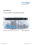
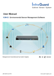
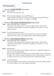
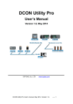
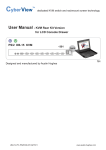
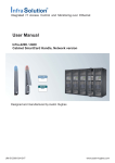
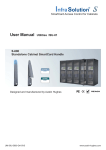
Intelligent Remote Power Management
User Manual
IPM-01, PDU management software
MTS switched PDU
MT monitored PDU
Designed and manufactured by Austin Hughes
UM-IPM-01-Q213V2
www.austin-hughes.com
Legal Information
First English printing, October 2002
Information in this document has been carefully checked for accuracy; however, no guarantee is given to the correctness
of the contents. The information in this document is subject to change without notice. We are not liable for any injury or
loss that results from the use of this equipment.
Safety Instructions
Please read all of these instructions carefully before you use the device. Save this manual for
future reference.
■
■
■
■
■
■
■
■
■
■
■
Unplug equipment before cleaning. Don’t use liquid or spray detergent; use a moist cloth.
Keep equipment away from excessive humidity and heat. Preferably, keep it in an air-conditioned environment with
temperatures not exceeding 40º Celsius (104º Fahrenheit).
When installing, place the equipment on a sturdy, level surface to prevent it from accidentally falling and causing dam
age to other equipment or injury to persons nearby.
When the equipment is in an open position, do not cover, block or in any way obstruct the gap between it and the
power supply. Proper air convection is necessary to keep it from overheating.
Arrange the equipment’s power cord in such a way that others won’t trip or fall over it.
If you are using a power cord that didn’t ship with the equipment, ensure that it is rated for the voltage and current
labelled on the equipment’s electrical ratings label. The voltage rating on the cord should be higher than the one listed
on the equipment’s ratings label.
Observe all precautions and warnings attached to the equipment.
If you don’t intend on using the equipment for a long time, disconnect it from the power outlet to prevent being dam
aged by transient over-voltage.
Keep all liquids away from the equipment to minimize the risk of accidental spillage. Liquid spilled on to the power
supply or on other hardware may cause damage, fire or electrical shock.
Only qualified service personnel should open the chassis. Opening it yourself could damage the equipment and invali
date its warranty.
If any part of the equipment becomes damaged or stops functioning, have it checked by qualified service personnel.
What the warranty does not cover
■
■
■
Any product, on which the serial number has been defaced, modified or removed.
Damage, deterioration or malfunction resulting from:
Accident, misuse, neglect, fire, water, lightning, or other acts of nature, unauthorized product modification, or
failure to follow instructions supplied with the product.
Repair or attempted repair by anyone not authorized by us.
Any damage of the product due to shipment.
Removal or installation of the product.
Causes external to the product, such as electric power fluctuation or failure.
Use of supplies or parts not meeting our specifications.
Normal wear and tear.
Any other causes which does not relate to a product defect.
Removal, installation, and set-up service charges.
□
□
□
□
□
□
□
□
Regulatory Notices Federal Communications Commission (FCC)
This equipment has been tested and found to comply with the limits for a Class B digital device, pursuant to Part 15 of the
FCC rules. These limits are designed to provide reasonable protection against harmful interference in a residential installation.
Any changes or modifications made to this equipment may void the user’s authority to operate this equipment. This
equipment generates, uses, and can radiate radio frequency energy and, if not installed and used in accordance with the
instructions, may cause harmful interference to radio communications.
However, there is no guarantee that interference will not occur in a particular installation. If this equipment does cause
harmful interference to radio or television reception, which can be determined by turning the equipment off and on, the
user is encouraged to try to correct the interference by one or more of the following measures:
■ Re-position or relocate the receiving antenna.
■ Increase the separation between the equipment and receiver.
■ Connect the equipment into an outlet on a circuit different from that to which the receiver is connected.
The company reserves the right to modify product specifications without prior notice and assumes no responsibility for any error which may appear in
this publication.
All brand names, logo and registered trademarks are properties of their respective owners.
Copyright 2011 Austin Hughes Electronics Ltd. All rights reserved.
UM-IPM-01-Q213V2
www.austin-hughes.com
Unpacking
The equipment comes with the standard parts shown on the package contents. Check and make sure they are included and in good
condition. If anything is missing, or damage, contact the supplier immediately.
Package contents
( 1 ) Vertical MTS / MT PDU x 1
- VMS mounting screw, set of 2 or 3
+
- VMB mounting bracket set
2 - 3 sets
M4
PEG
M4 x 2
Bracket x 2
M6
M6 x 2
M6 nut x 2
M6 nut
M4
OUT
IN
CUR
REN
22
5
T (A
)
ON
DIP
1
2
3
4
5
RES
6
7
8
ET
OUT
IN
CUR
REN
22
5
T (A
)
ON
DIP
1
2
3
4
5
RES
6
7
8
ET
M4
OR
( 2 ) Rackmount MTS / MT PDU x 1
M6 nut
M6
All electrical power and power control wiring must be installed by a qualified electrician and comply with local
and national regulations.
Power ON
■ Connect the PDU into an appropriately rated receptacle
■ When the PDU is power on, the LED display will light up. That means all outlets are activated
■ Keep the equipments in the power off position until it is plugged into the PDU
Don’t exceed the outlet, branch or phase limitations
UM-IPM-01-Q213V2
www.austin-hughes.com
Content
Over IP connection via
IP dongle
Part I. Setup and Connection
P. 1
< 1.1 > PDU meter setting & cascade
< 1.2 > IP dongle installation & connection
< 1.3 > Temp. & Humidity connection & specification
Part II. IP Configuration and Software
P. 7
< 2.1 > IP dongle configuration
< 2.2 > InfraPower Manager - IPM-01
FREE PDU management software
Part III. Data Export
P. 23
Part IV. FAQ
P. 27
< 4.1 > InfraPower Manager - IPM-01
< 4.2 > IP dongle
< 4.3 > Meter for MTS & MT PDU
< 4.4 > Others
Part V. Troubleshooting
P. 30
< 5.1 > PDU disconnection
< 5.2 > Replacement, removal or addition for PDU & IP dongle
UM-IPM-01-Q213V2
www.austin-hughes.com
Part I. Seup and Connection
< 1.1 > PDU meter setting & cascade
LINK
1
OUT
PDU cascade port
DIP Switch <ON>
DIP Switch <OFF>
CURRENT (A)
2
Current display
3
Dip switch
225
ON
1
4
DIP
2
3
4
5
6
7
8
Reset button
RESET
■
For rackmount PDU,
2
3
4
on the front panel left ,
1
on the rear panel
Cascaded PDUs setting
Using the
dip switch no. 1, 2, 3, 4 & 8
Cascaded PDUs
1st level PDU
2nd level PDU
3rd level PDU
4th level PDU
5th level PDU
6th level PDU
7th level PDU
8th level PDU
9th level PDU
10th level PDU
11th level PDU
12th level PDU
13th level PDU
14th level PDU
15th level PDU
16th level PDU
UM-IPM-01-Q213V2
1
On
Off
On
Off
On
Off
On
Off
On
Off
On
Off
On
Off
On
Off
to setup each PDU level as below :
Dip switch no.
2
3
4
On
On
On
On
On
On
Off
On
On
Off
On
On
On
Off
On
On
Off
On
Off
Off
On
Off
Off
On
On
On
Off
On
On
Off
Off
On
Off
Off
On
Off
On
Off
Off
On
Off
Off
Off
Off
Off
Off
Off
Off
P.1
8
Off
Off
Off
Off
Off
Off
Off
Off
Off
Off
Off
Off
Off
Off
Off
Off
www.austin-hughes.com
< 1.1 > PDU meter setting & cascade
1st level PDU
LINK
2nd level PDU
CAT. 5 / 6
cable
OUT
LINK
Up to 20 meters
CURRENT (A)
ON
1
2
3
4
5
6
7
ON
8
1
RESET
■
■
■
LINK
Up to 20 meters
2
3
4
5
6
225
DIP
ON
8
1
7
RESET
DIP
ON
OUT
CURRENT (A)
225
DIP
ON
CAT. 5 / 6
cable
OUT
CURRENT (A)
225
IP dongle
( refer to P.3 - 9 )
3rd level PDU
DIP
2
3
4
5
6
7
To LINK port
of next PDU
( Up to 16 levels )
8
RESET
DIP
ON
DIP
1 2 3 4 5 6 7 8
1 2 3 4 5 6 7 8
1 2 3 4 5 6 7 8
Dip switch setting
Dip switch setting
Dip switch setting
The PDU can be cascaded up to 16 levels
For IP PDU access simply connect 1 x IP dongle - IPD-01
1 x IP dongle allows access to 16 levels
Meter display setting
Using the
dip switch no. 5 & 7
to setup each PDU meter display as below :
Current display
Circuit A + Circuit B
Circuit A only
Circuit B only
Dip switch no.
5
Off
On
On
7
Off
Off
On
Audio alarm
Using the
dip switch no. 6
to setup each PDU audio alarm as below :
Dip switch 6
Off
On
Enable
Disable
UM-IPM-01-Q213V2
P.2
www.austin-hughes.com
< 1.2 > IP dongle installation & connection
To remote PDU over IP, users can order IP dongle :
IPD-01 IP dongle for vertical PDU
Vertical IP dongle installation steps :
- slide the IP dongle on the plate above the meter
- plug the RJ-45 connector of IP dongle into the LINK port of the 1st level PDU
meter
- use the CAT. 5 / 6 cable to connect IP dongle to network device
To LAN port
Customer’s network device
( router or hub )
IP dongle
■
1st level PDU
LINK
To LINK port
of the 1st PDU
OUT
CURRENT (A)
225
ON
1
2
3
4
5
6
7
RESET
UM-IPM-01-Q213V2
Please refer dip switch setting on P.1 - 2 for different level PDUs
2nd level PDU
CAT. 5 / 6
cable
Up to 20 meters
LINK
OUT
CURRENT (A)
225
DIP
ON
8
1
2
3
4
5
6
7
RESET
P.3
3rd level PDU
CAT. 5 / 6
cable
Up to 20 meters
LINK
OUT
CURRENT (A)
225
DIP
ON
8
1
DIP
2
3
4
5
6
7
RESET
8
To LINK port
of next PDU
( Up to 16 levels )
www.austin-hughes.com
< 1.2 > IP dongle installation & connection
IPD-H01 IP dongle for rackmount PDU
Horizontal IP dongle installation steps :
- fix the IP dongle on the rear side of rackmount PDU with 4 screws
- plug the RJ-45 connector of IP dongle into the LINK port of the 1st level PDU
meter
- use the CAT. 5 / 6 cable to connect IP dongle to network device
To LINK port of the 1st PDU
Rear side of rackmount PDU
IP dongle
To LAN port
Customer’s network device
( router or hub )
UM-IPM-01-Q213V2
P.4
www.austin-hughes.com
< 1.3 > Temp. & Humidity connection & specification
MT / MTS meter provides 1 sensor port for Temp. & Humidity monitoring. The user can see the
Temp. / Humidity reading not only from the local meter display but also from remote management
software.
•
low profile design with magnetic base for easy affixing to the rack cabinet
•
Plug n Play
•
sensor with 2M or 4M cord
Temp. & Humid. Sensor
Model :
IG - TH01 - 2M ( 2M cord )
IG - TH01 - 4M ( 4M cord )
IG-TH01
•
User MUST order TH sensor option before delivery
•
The length of the PDU may be increased by 50mm
UM-IPM-01-Q213V2
P.5
www.austin-hughes.com
< 1.3 > Temp. & Humidity Sensor Connection & Specification
Temp. & Humid. Sensor
Part no.
Temperature
Sensitivity
IG - TH01
Range
0 to 80°C ( 32 to 176°F )
Accuracy
±1.0°C typical ( ±2°F )
0.1°C ( 0.2°F )
Resolution
Response Time
Relative
Humidity
Sensitivity
5 to 30 sec
Range
0 to 100% R.H
Accuracy
0 to 100, ±8.0% R.H
20 to 80, ±4.5% R.H.
Resolution
1% R.H.
Response Time
Power
Requirement
Housing
Voltage
8 sec
12VDC, powered by sensor port
20mA
Current Consumption
Power consumption
0.24 Watt
Power on indicator
Red LED
Chassis & Cover
plastic
Color
Installation
Cable
Cable Length
Dark gray
Magnetic base for unrestricted installation
TH sensor w/ 2m cable ( standard )
TH sensor w/ 4m cable ( option )
Cable Specification
4-wired 3.5mm to RJ11
Cable Color
Environmental
Black
Operating
0 to 80°C Degree
Storage
-5 to 80°C Degree
Humidity
0~100%, non-condensing
Dimensions
Product
30L x 25Wx 18H mm
Weight
Net
Compatibility
InfraPower
10g
W / WS / Wi / WSi series PDU
X-2000 series
InfraSolution
InfraGuard
UM-IPM-01-Q213V2
Cabinet sensor system
P.6
www.austin-hughes.com
Part II. IP Configuration and Software
< 2.1 > IP dongle configuration
After the completion of IP dongle connection, please take the following steps to configure the IP dongle :
1. Prepare a notebook computer to download the IP setup utilities from the link :
http://www.austin-hughes.com/support/utilities/infrapower/IPdongleSetup.msi
2. Double click the IPDongleSetup.msi
and follow the instruction to complete the installation.
3. Go to each first level PDU with the notebook computer & a piece of CAT. 5 / 6 cable to configure the IP dongle by IP
setup utilities as below. Please take the procedure for all IP dongles ONE BY ONE.
IP dongle on 1st level PDU
CAT. 5 / 6 cable
To notebook computer
LAN port
To IP dongle
LAN port
Reconnect the IP dongle with the network device
( router or hub ), after finish IP dongle configuration.
Ensure the PDU in
power ON status
Write down the new IP address & password
for < Setup > purpose, refer to P.13
4. Click Scan to search the connected IP dongles
5. Enter the device name in the name field ( min. 4 char. / max. 16 char. ). The default is Name.
6. Enter the location in the location field ( min. 4 char. / max. 16 char. ). The default is Rack_001.
7. Enter the password in the password field for authentication ( min. 8 char. / max. 16 char. ). The default is 00000000.
8. Enter the new password in the new password field ( min. 8 char. / max. 16 char. ).
9. Re-enter the new password in the Confirm new password field.
10. Change the desired IP address / Subnet mask / Gateway, then click Save to confirm the setting to IP dongle.
11. The default IP address is as below:
IP address :
192.168.0.1
Subnet mask :
255.255.255.0
Gateway :
UM-IPM-01-Q213V2
192.168.0.254
P.7
www.austin-hughes.com
< 2.2 > InfraPower Manager - IPM-01, FREE PDU management software
InfraPower Manager, IPM-01, is a FREE PDU management software to enhance the features and benefits of the MTS
switched and MT monitored PDUs by providing a centralized and remote management platform, and total reporting with
detailed logs & event occurrences.
InfraPower Manager IPM-01 can support max. 5 concurrent login users and manage multi- IP dongles max. 15, hence the
concurrent login users can access & remote PDUs max. 240 ( 15 IP dongles x 16 level PDUs ).
Step 1. Software download
Prepare a management PC to download the free InfraPower Manager - IPM-01
from the link http://www.austin-hughes.com/support/software/infrapower/IPM-01.msi
Supported OS platform list :
- MS Windows XP Professional with SP3 (32bit only)
- MS Windows 7 Professional with SP1
- MS Windows 7 Ultimate with SP1
- MS Windows Server 2003 R2 Standard Edition with SP2
- MS Windows Server 2008 Standard Edition SP2
- MS Windows Server 2008 R2 Standard Edition SP1
Ensure the user logins in the management PC as a member of “Administrators” Group
before IPM-01 Installation and execution.
Step 2. System setup
Initial system setup on :
< User >
< Setup >
< Alarm >
< Scan >
< Refresh >
< Temp. >
< Backup >
< SNMP >
< Sys log >
< Past Sys log >
Step 3. Usage & operation
< Status >
< Details >
< Sensor >
< PDU log >
< Event >
< Past log >
UM-IPM-01-Q213V2
P.8
www.austin-hughes.com
Step 1. Software download
Double click the
IPM-01.msi
and follow the instruction to complete the installation.
IPM-01.msi
UM-IPM-01-Q213V2
P.9
www.austin-hughes.com
Step 1. Software download
UM-IPM-01-Q213V2
P.10
www.austin-hughes.com
Step 1. Software download
Double click the InfraPower Manager - IPM-01
IPM-01
InfraPower Manager
and follow the instruction to complete start-up setting.
For MS Windows 7 and MS Windows server 2008,
it requires to run a program with administrator rights before execution:
- Right click InfraPower Manager - IPM-01 , and then select Properties.
- Click the Compatibility tab.
- Tick the box Run this program as an administrator, and then click OK.
UM-IPM-01-Q213V2
P.11
www.austin-hughes.com
Step 1. Software Download
Completed
PostgreSQL password can be changed by user.
The password of PostgreSQL must contain at least three of the following four character groups:
- English uppercase characters (A through Z)
- English lowercase characters (a through z)
- Numerals (0 through 9)
- Non-alphabetic characters (such as !, $, #, %)
UM-IPM-01-Q213V2
P.12
www.austin-hughes.com
Step 2. System setup
Users can follow below step 1 - 3 to access the management PC and InfraPower Manager IPM-01
Step 1. Open Internet Explorer ( I.E. ), version 7.0 or above
Step 2. Enter the IP address of management PC into the address bar
( If fail to access, please ask MIS to check the service port of
the management PC )
Step 3. Enter the user name ( the default is admin )
Enter the password ( the default is 00000000 )
1
Login user
2
3
Login user
4
Login user
Router or hub
Login user
5
Login user
Management PC
InfraPower Manager IPM-01
Only Administrator is authorised to access < User >, < Setup >, < Alarm >, < Scan >, < Refresh >, < Temp. >, <
Backup > & < SNMP > for initial system setup
In < User > page, the administrator can create max. 5 concurrent login users and set the user name
& password. After this, all users can take the three steps above to access IPM-01.
UM-IPM-01-Q213V2
P.13
www.austin-hughes.com
Step 2. System setup
In < Setup > page, the administrator can activate the IP dongle group & set the group command
password.
UM-IPM-01-Q213V2
P.14
www.austin-hughes.com
Step 2. System setup
< Alarm >
UM-IPM-01-Q213V2
P.15
www.austin-hughes.com
Step 2. System setup
< Scan >
< Refresh >
< Temp. >
< Backup >
< SNMP >
UM-IPM-01-Q213V2
P.16
www.austin-hughes.com
Step 2. System setup
< Sys log > provides last 5000 events in < User >, < Setup >, < Alarm >, < Scan >,
< Refresh >, < Temp. >, < Backup > & < SNMP >.
< Past sys log > provides a search function in a certain period to find event occurrences in < User >,
< Setup >, < Alarm >, < Scan >, < Refresh >, < Temp. >, < Backup > & < SNMP >.
UM-IPM-01-Q213V2
P.17
www.austin-hughes.com
Step 3. Usage & operation
< Status > provides the users a scan function to monitor the PDUs of each IP dongle group one by
one & set the alarm amp for the PDU.
UM-IPM-01-Q213V2
P.18
www.austin-hughes.com
Step 3. Usage & operation
< Details > provides a detailed status about a certain PDU. The user can not only set the name &
location for PDU & each outlet, but also power ON / OFF the outlets one by one for
switched PDU.
UM-IPM-01-Q213V2
P.19
www.austin-hughes.com
Step 3. Usage & operation
< Sensor >
< PDU log > provides last 5000 PDU log records about a certain PDU by the user’s selection. The
software will generate a PDU log record in every one minute.
UM-IPM-01-Q213V2
P.20
www.austin-hughes.com
Step 3. Usage & operation
< Event > provides last 5000 events about PDU’s configuration & connection and
sensor’s configuration & connection in a certain IP dongle group.
UM-IPM-01-Q213V2
P.21
www.austin-hughes.com
Step 3. Usage & operation
< Past log > provides a search function in a certain period to find the log records about a certain
PDU or the event occurences about a certain IP dongle group.
Completed
UM-IPM-01-Q213V2
P.22
www.austin-hughes.com
Part III. Data Export
1)
Select IP Dongle group.
2)
Tick the box of PDU log & ignore the PDU level selection.
3)
Enter the period of PDU log to export. (min. 1 day, max. 31 days)
4)
Click Export and a Message from webpage dialog box pops up.
5)
Click OK to confirm the export process. It may take several minutes to complete.
Processing............
UM-IPM-01-Q213V2
P.23
www.austin-hughes.com
6)
Right click the PDU level below.
7)
Select Save Target As to download the PDU log file.
UM-IPM-01-Q213V2
P.24
www.austin-hughes.com
8)
Select the path & click Save to complete the download process.
Please take Step 6, 7 & 8 for the other PDU levels one by one.
UM-IPM-01-Q213V2
P.25
www.austin-hughes.com
•
Below is the sample of a PDU log file in MS Excel, CSV format.
•
User can use the data for analysis purpose.
Completed
UM-IPM-01-Q213V2
P.26
www.austin-hughes.com
Part IV. FAQ
< 4.1 > InfraPower Manager - IPM-01
1. What is InfraPower Manager?
The InfraPower Manager IPM-01 is a Windows based system to consolidate management of max. 240
PDUs via 15 IP dongles, using a simple web interface which monitors and controls the MTS / MT PDUs
in the data center. Authorized users have a secure control over outlets to power ON / OFF at the managed device level. It also provides the detailed PDU and event logged records, and sends alarm email
once ampere overloading.
Please find the link below:
http://www.austin-hughes.com/support/software/infrapower/IPM-01.msi
2. Which OS platform does IPM-01 support?
- MS Windows XP Professional with SP3 (32bit only)
- MS Windows 7 Professional with SP1
- MS Windows 7 Ultimate with SP1
- MS Windows Server 2003 R2 Standard Edition with SP2
- MS Windows Server 2008 Standard Edition SP2
- MS Windows Server 2008 R2 Standard Edition SP1
Ensure the user logins in the management PC as a member of “Administrators” Group
before IPM-01 Installation and execution.
3. Which database does the IPM-01 support?
PostgreSQL
4. What is the PostgreSQL default password for IPM-01?
1qaz2WSX
5. How can I receive alarm email and get full log report?
Ensure that IPM-01 is executed and the alarm server is configured properly and being enabled.
6. What is the default login name & password of IPM-01?
Default login name “admin” & password “00000000”
7. What is the command password of IPM-01?
Each IP dongle group has its command password. It will be requested for any PDU configuration and
control. The administrator can set different command password for different IP dongle group or all IP
dongle groups use the same password.
8. The MTS / MT PDUs can’t be found by IPM-01?
Please double check the cable connection and the level setting of each PDU. If a cascade chain has
duplicate the level PDUs, it will cause this problem.
9. Is it possible to manage the MTS / MT PDUs from different workstations?
Yes, the InfraPower manager supports 5 concurrent login users from different workstations.
UM-IPM-01-Q213V2
P.27
www.austin-hughes.com
10. Can the MTS / MT PDUs connect the KVM switch?
Yes, only CyberView IP KVM switch. In this connection, IP dongle will not be needed.
For the details, please find the link below:
http://www.austin-hughes.com/support/usermanual/infrapower/UM-IPS-01.pdf
11. Does the IP dongle support web browser access?
Yes, the IP dongle features a browser-based built-in graphical user interface (GUI) that can configure,
monitor and power control to individual outlets.
For the details, please find the link below:
http://www.austin-hughes.com/support/usermanual/infrapower/UM-PPS-01.pdf
< 4.2 > IP dongle
1. What is the IP dongle?
The IP dongle provides a simple and economical way to consolidate management of max. 16 pcs
MTS / MT PDUs, by a single IP connection to the network.
2. What is the IP setup utilities?
This is a windows application used to assign the IP address of IP dongle. You can download the IP
setup utilities from the link below:
http://www.austin-hughes.com/support/utilities/infrapower/IPdongleSetup.msi
3. Does the IP dongle support DHCP (Dynamic Host Configuration Protocol)?
No, the IP dongle only works with static IP-address.
4. How can I reset the IP dongle password to the factory default value?
Press the reset button of IP dongle for at least 8 seconds to reset the IP dongle to the factory default
value as below:
IP address: 192.168.0.1
Password: 00000000
5. Will the reset of IP dongle affect the power to the outlets?
No, the IP dongle operates on a separate circuit, so the power to the outlets will remain unchanged.
6. How can I replace a failed IP dongle?
As the IP dongle is hot swappable, without power disconnection, you can unplug the RJ45 connector
and slide out the failed IP dongle from the MTS / MT PDU. Then replace a new one for the PDU and
re-configure the IP address to fit your network setting. ( Please refer to the user manual P. 5 )
UM-IPM-01-Q213V2
P.28
www.austin-hughes.com
< 4.3 > Meter for MTS & MT PDU
1. What is feature of the MT PDU?
The MT PDU offers simple & highly reliable power distribution to multiple equipments, and built-in a
digital ampere meter indicates the total power consumption of equipment connected to the PDU. The
digital ampere meter has an interface which can connect to an IP dongle to the ethernet network, which
allows managers to real-time remote monitor the PDU load thru the InfraPower manager (IPM-01).
2. What is feature of the MTS PDU?
The MTS PDUs offers the same features as MT PDUs, with an addition remote control power capability
to individual PDU outlets. The remote outlet power control allows power on/off functionality for power
recycling to reboot locked-up equipment and to avoid unauthorized use of individual outlets.
3. Which types of outlet can MTS PDU support?
The MTS PDU supports IEC 60320/C13, IEC 60320/C19, NEMA 5-15/20R & BS1363 outlet type.
4. Can the MTS and MT PDUs cascade together?
Yes, the MTS & MT model PDUs can connect together as a cascade chain.
5. If one of the cascaded MTS / MT PDU loses power, will it affect other PDUs in the same
chain?
No, the other cascaded MTS / MT PDUs in upper & lower level will not be affected.
6. What is the maximum cabling distance between two cascaded PDUs?
Up to 20 meter (66 feet) of CAT. 5 / 6 cable.
7. What is the maximum cascade level of the MTS / MT PDU in a chain?
16 levels
< 4.4 > Others
1. Does the InfraPower PDU has the overpower protection?
Yes, the PDU provides the resettable fuse or optional circuit breaker for the overpower protection.
2. What is the standard inlet cable length of InfraPower?
3 meter ( 9.9 feet ).
3. Where can I find the Catalogue / User manual /Model list / Wire diagram of InfraPower
PDUs?
Please visit the www.austin-hughes.com
4. How can we get a further support?
Please send the email to [email protected] or [email protected]
UM-IPM-01-Q213V2
P.29
www.austin-hughes.com
Part V. Troubleshooting
< 5.1 > PDU disconnection
1.
GUI shows a certain level PDU disconnected
Step 1. PDU power off ?
Check the PDU is power ON or not.
Step 2. PDU level setting duplicated in the same PDU group ?
Check and make sure PDU level is unique and not duplicated in the same PDU group.
(Please refer to P.1 for the PDU level setting)
2.
GUI shows from a certain level PDU to the last one disconnected
Step 1. Cable disconnected, loose or defective ?
Check the Cat. 5/6 cable connection to PDUs and network devices. Make sure the
connectors are firmly attached. And check if any defects on your cable or not. If yes,
replace a new one.
Step 2. The first disconnected PDU failed ?
Unplug the Cat. 5/6 cable on the first disconnected PDU, then plug it to the second
disconnected PDU to check if the problem caused by the first disconnected PDU.
3.
GUI shows the whole group of PDU(s) disconnected
Step 1. Cable disconnected, loose or defective ?
Check the Cat. 5/6 cable connection to PDUs and network devices. Make sure the
connectors are firmly attached. And check if any defects on your cable or not. If yes,
replace a new one.
Step 2. IP dongle failed ?
i.
Check if the network setting of the IP dongle is correct or not. If duplicated IP address
is in a network, it may cause such problem.
ii.
Disconnect the IP dongle from the network and try to direct connect the Cat. 5/6 cable
from IP dongle < LAN > port to a computer network port and use IP Setup utilities
to check if the IP dongle can be found or not. If it cannot be found, the IP dongle may
be failed.
Step 3. 1st level PDU failed ?
Move the IP dongle from 1st level PDU to 2nd level PDU to check if the problem
caused by 1st level PDU’s failure or not. If yes, replace 1st level PDU.
UM-IPM-01-Q213V2
P.30
www.austin-hughes.com
< 5.2 > Replacement, Removal or addition for PDU & IP dongle
1.
How to replace the failed IP dongle ?
Step 1. Prepare a new IP dongle.
Step 2. Disable alarm email in <Alarm> page.
Step 3. Replace the failed IP dongle with the new one on 1st level PDU.
Step 4. Configure the setting of the new IP dongle same as the old one.
(Please refer to P.5 for IP dongle configuration)
Step 5. Click Start Connection in <Status> page for the relevant IP dongle.
Step 6. Enable alarm email in <Alarm> page again.
2.
How to replace the failed 1st level PDU with a new one ?
Step 1. Prepare a new PDU and set the PDU to 1st level.
(Please refer to P.1 for the PDU level setting)
Step 2. Disable alarm email in <Alarm> page.
Step 3. Power off & unplug the device(s) which connected to the PDU.
Step 4. Power off & remove the failed 1st level PDU from connection.
Step 5. Install the IP dongle on the new 1st level PDU.
Step 6. Install and connect the new PDU.
Step 7. Power on the new PDU and connect to the device(s).
Step 8. Click Start Connection in <Status> page for the relevant IP dongle.
Step 9. Configure the new PDU in <Status> and <Details> page such as
Alarm Amp , Name, Location…
Step 10. Enable alarm email in <Alarm> page.
3.
How to replace a failed certain level PDU with a new one ?
Step 1. Prepare a new PDU and set the PDU level accordingly.
(Please refer to P.1 for the PDU level setting)
Step 2. Prepare an appropriate length Cat. 5/6 cable.
Step 3. Disable alarm email in <Alarm> page.
Step 4. Use the Cat. 5/6 cable to bridge over the failed PDU which will be
replaced to minimize log/data loss.
Step 5. Power off & unplug the device(s) which connected to the failed PDU.
Step 6. Power off & remove the failed PDU from connection.
Step 7. Install the new PDU, cancel the cable-bridging and reconnect the
PDU to the last and next one.
Step 8. Power on the new PDU and connect to the device(s).
Step 9. Configure the new PDU in <Status> and <Details> page such as
Alarm Amp, Name, Location…
Step 10. Enable alarm email in <Alarm>.
Ignore step 2 & 4 if the failed PDU is in the last level.
UM-IPM-01-Q213V2
P.31
www.austin-hughes.com
< 5.2 > Replacement, Removal or addition for PDU & IP dongle
4.
How to move out a PDU (without a replacement) ?
Step 1. Prepare an appropriate length Cat. 5/6 cable.
Step 2. Disable alarm email in <Alarm> page.
Step 3. Use the Cat. 5/6 cable to bridge over the removed PDU to minimize log/data loss.
Step 4. Power off & unplug the device(s) which connected to the PDU.
Step 5. Power off & remove the PDU from connection.
Step 6. Click Disable Monitoring in <Details> page to stop monitoring the removed PDU.
Step 7. Enable alarm email in <Alarm> page.
If the removed PDU NOT in the last level, you MUST reconfigure and reset the level for the
affected PDU(s) which next to the removed PDU.
Ignore step 1 & 3 if the removed PDU is in the last level.
5.
How to add an extra PDU to an existing PDU group ?
Step 1. Prepare a PDU and set the PDU level accordingly.
(Please refer to P.1 for the PDU level setting )
Step 2. Prepare an appropriate length Cat. 5/6 cable.
Step 3. Disable alarm email in <Alarm> page.
Step 4. Install and connect the new PDU.
Step 5. Power on the new PDU.
Step 6. Click Search in <Status> page to search the new installed PDU.
Step 7. Configure the new PDU in <Status> and <Details> page such as
Alarm Amp , Name, Location…
Step 8. Enable alarm email in <Alarm> page.
If the added PDU NOT in the last level, you MUST reconfigure and reset the level for the
affected PDU(s) which next to the added PDU.
The company reserves the right to modify product specifications without prior notice and assumes no responsibility
for any error which may appear in this publication.
All brand names, logo and registered trademarks are properties of their respective owners.
Copyright 2013 Austin Hughes Electronics Ltd. All rights reserved.
UM-IPM-01-Q213V2
P.32
www.austin-hughes.com