Download User manual DMX CONTROL 512
Transcript
User manual
DMX CONTROL 512
Table of contents
1. SAFETY INSTRUCTIONS .............................................................................................. 4
2. OPERATING DETERMINATIONS .................................................................................. 4
3.OVERVIEW ...................................................................................................................... 6
3.1.REAR PANEL CONNECTIONS................................................................................ 6
3.2.FRONT PANEL ......................................................................................................... 6
4.MENU............................................................................................................................... 6
4.1.CHOOSE FIXTURES ............................................................................................... 6
4.2.PATCH FIXTURES ................................................................................................... 7
4.3.MULTI FIXTURE ....................................................................................................... 7
4.4.MODIFY FIXTURE .................................................................................................... 7
4.5.COPY FIXTURE ....................................................................................................... 8
4.6.PAN AND TILT INVERT ............................................................................................ 8
4.7.SET MIDI CHANNEL ................................................................................................ 9
4.8.VIEW MEMORY SIZE ............................................................................................... 9
4.9.SAVE MEMORY FILE ............................................................................................... 9
4.10.LOAD MEMORY FILE ............................................................................................. 9
4.11.UPDATE SOFTWARE............................................................................................. 9
4.12.LOCK/UNLOCK MEMORY ..................................................................................... 9
4.13.ERASE ALL MEMORY ........................................................................................... 9
5.SWITCH AND CONTROL DESCRIPTIONS ................................................................. 10
5.1.NUMBER SWITCHES 1-16 .................................................................................... 10
5.2.FIXTURE ................................................................................................................ 10
5.3.CHANNEL FADERS ............................................................................................... 10
5.4.BANK SWITCH ....................................................................................................... 10
5.5.JOYSTICK ............................................................................................................... 10
5.6.FINE SWITCH ......................................................................................................... 11
5.7.TRACKBALL ........................................................................................................... 11
5.8.BLACK SWITCH ..................................................................................................... 11
6.SCENES ........................................................................................................................ 11
6.1.RECORDING SCENES .......................................................................................... 11
6.2.RECALLING SCENES ........................................................................................... 11
6.3.ERASE SCENE ...................................................................................................... 11
2
7.PRESETS ...................................................................................................................... 12
7.1.RECORDING PRESETS ........................................................................................ 12
7.2.RECALLING PRESETS ......................................................................................... 12
7.3.ERASE PRESET .................................................................................................... 13
7.4.EDITING PRESETS ............................................................................................... 13
7.5.COMBINING PRESETS ......................................................................................... 13
8.CHASES ........................................................................................................................ 13
8.1.RECORDING CHASES .......................................................................................... 13
8.2.RECALLING CHASES ........................................................................................... 14
8.3.ERASING CHASES ................................................................................................ 15
8.4.EDITING CHASES ................................................................................................. 15
8.5.FACTORY CHASES ............................................................................................... 15
8.6.AUDIO SWITCH ...................................................................................................... 15
8.7.BEAT SWITCH ........................................................................................................ 15
9.SHOWS .......................................................................................................................... 15
9.1.RECORDING SHOWS ........................................................................................... 15
9.2.RECALLING SHOWS ............................................................................................. 16
9.3.ERASING SHOWS ................................................................................................. 16
9.4.EDITING SHOWS ................................................................................................... 17
10.MIDI .............................................................................................................................. 17
10.1.MEMORY BACKUP WITH MIDI ............................................................................ 17
10.2.MEMORY RESTORE WITH MIDI .......................................................................... 17
11.USING THE COMPUTER PORT ................................................................................. 18
11.1.CONFIGURING YOUR PC .................................................................................... 18
11.2.MEMORY BACKUP USING THE COMPUTER PORT ......................................... 18
11.3.MEMORY RESTORE USING THE COMPUTER PORT ....................................... 19
11.4.UPDATING THE SOFTWARE ............................................................................... 19
12.TECHNICAL SPECIFICATIONS ................................................................................. 20
13.CLEANING AND MAINTENANCE ............................................................................. 20
APPENDIX A - FIXTURE LIBRARY ................................................................................ 21
3
Keep this device away from rain and moisture!
Unplug mains lead before opening the housing!
FOR YOUR OWN SAFETY, PLEASE READ THIS USER MANUAL CAREFULLY
BEFORE YOU INITIAL START - UP!
1. SAFETY INSTRUCTIONS
Every person involved with installation and maintenance of this device have to:
- be qualilfied
- follow the instructions of this manual
CAUTION!
Be careful with your operations. With a high voltage you can suffer
a dangerous electric shock when touching the wires!
This device has left our premises in absolutely perfect condition. In order to maintain this condition and to ensure
a safe operation, it is absolutely necessary for the user to follow the safety instructions and warning notes written
in this manual.
Important:
The manufacturer will not accept liability for any resulting damages caused by the non-observance of this manual
or any unauthorized modification to the device.
Please consider that damages caused by manual modifications to the device are not subject to warranty.
Never let the power-cord come into contact with other cables! Handle the power-cord and all connections with the
mains with particular caution!
The power plug has to be accessable after installing the device.
Make sure that the power cord is never crimped or damaged by sharp edges. Check the device and the powercord
from time to time.
Always disconnect from the mains, when the device is not in use or before cleaning it.
The electric connection, repairs and servicing must be carried out by a qualified employee.
2. OPERATING DETERMINATIONS
This device was designed for indoor use only.
If the device has been exposed to drastic temperature fluctuation (e.g. after transportation), do not switch it on
immediately. The arising condensation water might damage your device. Leave the device switched off until it has
reached room temperature.
Do not shake the device. Avoid brute force when installing or operating the device.
When choosing the installation-spot, please make sure that the device is not exposed to extreme heat, moisture
or dust. There should not be any cables lying around. You endanger your own and the safety of others!
Operate the device only after having familiarized with its functions. Do not permit operation by persons not
qualified for operating the device. Most damages are the result of unprofessional operation!
Please use the original packaging if the device is to be transported.
4
Never put any liquids on the device or close to it. Should any liquid enter the device nevertheless, disconnect
from mains immediately. Please let the device be checked by a qualified service technician before you operate it
again. Any damages caused by liquids having entered the device are not subject to warranty!
Please consider that unauthorized modifications on the device are forbidden due to safety reasons!
If this device will be operated in any way different to the one described in this manual, the product may suffer
damages and the guarantee becomes void. Furthermore, any other operation may lead to dangers like shortcircuit, electric shock, etc.
5
3.OVERVIEW
The DMX CONTROL 512 is a lighting controller.16 lighting fixtures of up to 32 channels each can be controlled
from a DMX 512 output. Control of up to 512 lighting channels is possible. Support of ROBE as well as other
popular brands is included in the setup menu.
The operating system uses flash memory so that the software can be updated from a computer
Software updates will be made available on the ROBE web site at ww.robe.cz.
3.1.REAR PANEL CONNECTIONS
• Power input for an external 9V power supply. This requires a transformer with a 9VDC output at
500ma. The plug polarity is + center with an inside diameter of 2.1 mm.
• DMX 512 output using a 3 pin XLR connector. There is a polarity switch which swaps pins 2 and 3.
Some lighting fixtures receive data minus on pin 2 and some on pin 3. The more commonly used
polarity is data minus on pin 2 (switch is to the right as you’re looking at the back of the unit).
• MIDI in and out - used for calling scenes in an automated installation.
• 9 pin RS-232 connector - used for connection to a PC to update the
software or backup the memory. It can also be used to connect to a mouse or trackball.
• Audio input - used for syncing chases to an external audio source. This is a line level input for
connection to the line output of a mixing console. Do not connect speaker level signals to this.
3.2.FRONT PANEL
Front panel features include assorted switches for programming, eight 60mm faders for direct control of
lighting fixture channels, a data entry wheel, a joystick for pan and tilt control and a backlit display for
programming.
4.MENU
The menu switch is used to configure the DMX CONTROL 512 for your particular lighting setup. The left and
right cursor switches, the + and - switches, and the data input wheel allow you to select settings for the
various menus that appear on the display. Pressing the menu switch displays the message “Press enter
to” on the top line of the display. You will be given a choice of menu items on the bottom line of the
display. You can cycle through the choices using the + and - switches or the data wheel. Press “enter” to
select the desired menu item. After selecting from the menu, the cursor switches will allow you to select a
field on the display to edit and the + and - switches or the data wheel will allow you to change the value in
that field. An underline cursor shows the selected field. The “enter” switch must always be pressed
following any change to make it permanent. This allows you to look at all of the possible choices first.
Several of the menu items are hidden to prevent unauthorized or accidental changes to the memory. The
“memory lock/unlock” function is hidden as well as the “erase all memory” function. These choices can
only be selected by pressing and holding down the “add” switch while selecting these last items from the
menu list. This is a safety feature for the benefit of installers who wish to protect the memory from
unauthorized tampering.
The various menu items are explained in the following paragraphs.
4.1.CHOOSE FIXTURES
To select from a list of lighting fixtures in the fixture library, use the + or - switch or the data wheel to first
select the fixture number (from 1 to 16). Next, select the type of fixture by moving the cursor to the fixture
type by pressing the right arrow switch and then using the + or – switch or the data wheel to make a
selection. You must press, “enter” to record the choice. You can also press, “erase” to select “No
Fixture” which is one of the fixture choices. If auto patch is enabled, a warning will appear telling you that
some DMX start addresses may be changed. Press “yes” to confirm or “no” to exit. After pressing
6
“yes” the message “DONE” will appear for 1 second. If auto patch is enabled, the start addresses of any
fixtures above the selected fixture will be adjusted to accommodate the new fixture.
There is a list of all of the included fixtures in the back of this manual. If a particular fixture is not
included in the list, you can select one that is similar to the one you want and then use the “Modify
Fixture” feature to create it.
4.2.PATCH FIXTURES
This allows you to turn auto patch on and off and also allows you to set the DMX starting address for
each fixture. Auto patch must be turned off to change the start addresses. To turn auto patch on or off,
place the cursor under the word “ON” or “OFF” next to “AUTO PATCH”, then use the + or - switch
or the data wheel to change it. You must press, “enter” for the change to take effect. If you are turning
auto patch on, a warning will appear telling you that some DMX starting addresses may change. Press
“yes” to proceed or “no” to exit. Auto patch will assign an address to each fixture in ascending order
with each DMX address immediately following the last channel of the previous fixture.
You can select from fixtures 1-16 and see the starting address for each fixture. You can then move the
cursor under any of the three digits of the channel number to select a new starting address. If auto patch is
on you will not be able to change the address. You must press, “enter” to record any change. The
message “DONE” will appear for 1 second to confirm.
4.3.MULTI FIXTURE
DMX CONTROL 512 supports intelligent lighting fixtures that use as many as 32 DMX channels. Since most
fixtures use fewer than 32 channels, DMX CONTROL 512 allows you to configure a group of fixtures that are
of the same type, under a single fixture number. For example if you have selected a 4-channel scanner for
fixture number 1, you can set “multi” to 8. When fixture 1 is selected you will be able to use all 32
channels available for fixture 1 to control 8 of these scanners.
NOTE: This feature is for controlling large numbers of small 1, 2, 3 or 4 channel fixtures so that a fixture
number is not used up on one small fixture.
You will be able to control the individual channels of each fixture separately using the 4 banks of 8 faders.
When using the joystick, all of the multi fixtures within that fixture number will respond if they have a pan
and tilt feature. To control individual pan and tilt levels separately you will have to use the faders.
To program the multi fixtures, move the cursor to the fixture number and use the + and - switches or data
wheel to select a fixture number. Move the cursor to the multi number (to the right of “X”) to increment
or decrement this value. You can only choose numbers between 1 and the maximum number of fixtures
that will fit into 32 channels. If it is a 4 channel fixture the multi value can be no higher than 8. You must
press, “enter” to record the change. If auto patch is enabled you will be given the warning that some
addresses may change. Press “yes” to continue or “no” to exit.
4.4.MODIFY FIXTURE
This allows you modify the channel attributes of a fixture. You can also use this to create a new fixture that
isn’t in the library. To do this you must first select a fixture as described above in the “Choose Fixture”
section. When trying to create a new fixture, choose something that is similar to the one you are trying to
create or start with the “Generic Dimmer” which is the first choice from the list. You can later use the
“Copy Fixture” feature as described in the next section to duplicate the new fixture.
There are nine fixture attributes that can be modified. The attributes are: fixture name, number of channels,
black channel, black value, pan channel, pan fine channel, tilt channel, tilt fine channel and crossfade mode.
After you have selected the “Modify Fixture” menu, use the cursor switches to move the underline cursor
to the fixture number to select the fixture you want to modify. Next move the cursor to the “attribute” which is
displayed immediately to the right of the fixture number to select from the nine fixture attributes.Next move the
cursor to the bottom line of the display to select the value for the attribute you are changing.
You must always press “enter” to record any changes you make to an attribute. The message “DONE”will appear
in the display when the change has been recorded. The fixture attributes are described in the
following paragraphs.
NAME is the fixture name that appears whenever you select or deselect a fixture. You may want to modify
this attribute on all of your fixtures to show fixture purpose or location. You must place the underline
cursor on the character you want to edit then use the + or – switch or the data wheel to select a character.
7
CHANNELS is the total number of channels for the fixture. This can be any number from 1 to 32. When
you change the number of channels be aware that other things such as fixture addresses and number of
multi fixtures can be automatically changed if you drastically change the number of channels for a fixture
that has already been set up and is in use. Fixture attributes such as black channel, pan or tilt will be
automatically disabled if you select a number that is smaller than the channel numbers that are already
assigned to those attributes. For example if you have already assigned pan to channel 8 and you reduce the
total number of channels for the fixture to 4, pan will automatically be set to “none”. Likewise if you
increase the number of channels from 8 to 9 and you had previously set up 4 multi fixtures using all 32
channels, the multi fixture setting will automatically be reset back to 1.
BLACK CHANNEL is the channel that will be affected when the “black” switch is pressed. You can
choose any available fixture channel as well as “ALL” which will force all channels to the selected black
value.
BLACK VALUE is the DMX value that will be sent to the selected black channel(s). This will
accommodate fixtures that use the gobo wheel for blackout and that use a value other than 0 to set the
gobo wheel to black. You may also want to blackout all channels to a value other than 0 since this is used
as a reset by some fixtures. For some fixtures a value of 1 achieves the same result as a value of 0 for
blackout.
PAN CHANNEL is the channel used by the fixture for pan. This can also be set to “none” if the fixture
does not have a pan feature. This is also the pan coarse channel or pan high byte channel for those fixtures
that use two channels to control pan. This directs the joystick output as well as other pan functions.
PAN FINE is for fixtures that use two channels to control pan. This is also referred to sometimes as the
pan “low byte” channel. Set this to “none” if the fixture uses only one channel for pan. The joystick will
control this channel with “fine” mode turned on.
TILT CHANNEL is the same as described above for pan channel except that it controls tilt.
TILT FINE is the same as described above for pan fine except that it controls tilt.
FADE MODE is used to set the crossfade method for each of the fixture’s channels. Use the + and switches or data wheel to select the desired channel, then move the cursor to the value to select the
crossfade mode. The choices are “crossfade”, “snap before fade” and “snap after fade”. You must
press “enter” after each channel has been programmed.
“Crossfade” will cause a channel to smoothly fade from one setting to another when changing scenes.
The crossfade time will vary from scene to scene depending on how that scene was programmed. Use this
setting for channels that control functions like pan and tilt or dimming to achieve a smooth transition from
scene to scene. If you use this setting for gobo or color wheel channels, this will cause the wheels to step
through all positions between the start and end positions of a long fade. This is usually the default setting
for pan, tilt and dimmer channels.
“Snap before fade” will cause the channel to jump immediately to the next scene level as soon as the new
scene is called. Use this setting for channels that control motor speed so that pan and tilt will move at the
correct speed during the fade. You can also use this setting for wheel channels that you want to change at
the start of long crossfades. This is usually the default setting for speed and mode channels.
“Snap after fade” will cause the channel to jump immediately to the next scene level at the end of a
crossfade. Use this setting for wheels and effects that you want to take effect after a long crossfade is
complete. This is usually the default setting for color and effects wheels.
4.5.COPY FIXTURE
This is used to copy the fixture type from one fixture number to another. This feature saves time by letting
you copy the fixture selection rather than searching through the list when setting up a group of fixtures
that are all the same type. Select a fixture number to copy from and to. Press, “enter” to complete the
copy process. If auto patch is enabled you will be given the warning that some addresses may change.
Press “yes” to continue or “no” to exit. If a fixture is already set up at the “copy to” location, you will
be asked if you want to copy over the existing fixture, press “yes” to copy over it or “no” to exit.
4.6.PAN AND TILT INVERT
The joystick can be used to control pan and tilt if a fixture has a pan and tilt feature. Sometimes a fixture is
8
oriented in a way so that its pan or tilt movement is opposite that of the joystick movement. You can use
this to invert the direction of the pan or tilt as it applies to the joystick for each fixture. This setting will not
affect the faders when they are used to control pan or tilt. Select the fixture then select “Normal” or
“Inverted”, then press, “enter” to save the selection.
4.7.SET MIDI CHANNEL
This allows you to select the MIDI channel that DMX CONTROL 512 will use when sending and receiving
MIDI messages. Select a value from 1-16 and press enter. On the bottom line of the display you can also
enable extra MIDI channels by selecting a value from 0 - 9. Extra MIDI channels will allow you to use
more than one MIDI channel to call large numbers of scenes and shows. If extra is set to 0, only messages
on the selected MIDI channel will be used. If set to 1 or higher, messages can be used on the next
consecutive MIDI channels as well. Read the section on MIDI for more info.
4.8.VIEW MEMORY SIZE
This allows you to see how much memory is left for scenes and shows. It is displayed in kilobytes
remaining. Memory usage varies depending on the size and complexity of the scenes.
4.9.SAVE MEMORY FILE
This allows you to back up the memory to a PC using the RS-232 port or to a MIDI device.
Pressing, “enter” brings up a second menu selection allowing you to choose the Com port or the MIDI
port to send the memory file to. Read the section at the end of this manual on backing up the memory for
more information.
4.10.LOAD MEMORY FILE
This allows you to restore the memory from a backup that was made using the RS-232 port and a PC
Pressing “enter” configures the RS-232 port for memory read and waits for the file to be sent from a PC.
Read the section at the end of this manual on using the computer port for details on how to back up and restore
the memory this way. The only way to exit this menu is to turn the power off.
Warning: the current memory will be overwritten.
4.11.UPDATE SOFTWARE
This allows you to update the DMX CONTROL 512 software using a computer connected to the RS-232 port.
Message “DOWNLOAD NEW PROGRAM” will appear when you press “enter”. DMX control 512 will wait for the
proper file to be sent from a PC to the RS-232 port.
The message “RECEIVING NEW PROGRAM” will appear as the computer sends the new software file.
Upon completion, the system will reboot. The only way to exit this menu is to turn the power off.
You can also call this menu on power up by pressing and holding menu” and “erase” together while turning on
the power. Refer to the section titled “Using the Computer Port” at the end of this manual for more details
on how to do this.
All software updates will be made available from the factory website.
4.12.LOCK/UNLOCK MEMORY
This is one of the hidden menu items that can only be selected while holding the “add” switch when
cycling through the menu selections.
This feature allows you to lock the memory to prevent someone from changing or erasing anything that
has been recorded. The message “MEMORY LOCKED, CAN’T RECORD” will appear if the memory
is locked and anyone presses the record switch. All other menu items that are not hidden will also be
locked out in order to protect the memory.
To lock or unlock the memory, use the + and - switches or the data wheel to select the desired state, then
press “enter”.
4.13.ERASE ALL MEMORY
9
This is another one of the hidden menu items that can only be selected while holding the “add” switch
when cycling through the menu selections.
This menu item allows you to clear the entire memory of DMX CONTROL 512. This does not erase the
software that runs the system but erases all of the scene, preset, chase and show data as well as the system
parameters such as fixture assignments. The message “ARE YOU SURE? HOLD “YES” 5 SEC” will
appear in the display. Press and hold “yes” until the system reboots or press “no” to exit.
5.SWITCH AND CONTROL DESCRIPTIONS
The following paragraphs outline the various switches and controls with their functions.
5.1.NUMBER SWITCHES 1-16
The array of 16 switches on the left side of the panel that are numbered 1-16 are multi-purpose. The
function switches that are to the right of these determine their purpose. Only one function is selected at a
time and the LED for the particular function will be lit when selected. The following is a description of
each function.
5.2.FIXTURE
This switch allows you to select fixtures for programming. With the “fixture” switch LED lit, the number
switches 1-16 are used to select an active fixture. When a fixture is selected it can be directly controlled
using the faders or the joystick. A selected fixture can also be controlled using a preset. A fixture does not
have to be selected in order to be controlled by scenes or shows. If a fixture is not selected it will only be
disconnected from the manual controls, the fixture is not turned off.
When a fixture is selected its name will appear in the LCD. If no fixture type has been assigned to that
number, it can’t be turned on. Pressing and holding one of the number switches will solo that fixture.
5.3.CHANNEL FADERS
Just below the number switches are 8 faders that can be used to control the individual channels within each
fixture. You can address up to 32 channels per fixture by using 4 banks of 8 faders. The bank switch to
the left of the faders is used to select which bank of 8 channels is currently active. The LED to the left of
the faders shows the current bank. The channel numbers controlled by the faders are printed to the left of
each fader. For example the first fader can control channels 1, 9, 17 or 25 depending on which bank is
selected. If a fixture has less than 32 channels then some banks and some faders will not be used. Before
the channel faders can control a fixture, that fixture must be selected. Any number of fixtures can be
controlled at once. If for example all fixtures are enabled, moving fader 1 with bank 1 selected will change
channel 1 on every fixture.
If you are using the “multi fixture” feature of DMX CONTROL 512, the channel faders can be used to control
each channel of every fixture within the multi fixture group. If for example you have programmed 8
fixtures having 4 channels each, faders 1-4 will control the first fixture of the multi fixture group, faders 58 the second and so on.
5.4.BANK SWITCH
The bank switch selects the current bank of channels controlled by the 8 faders. This allows you to control
up to 32 channels per fixture using only 8 faders. The bank LED next to the faders will show the currently
selected bank and the numbers printed next to each fader show the channel number or scene number of the
fader for the selected bank. As a convenience the bank select will only go as high as needed for the size of
the currently selected fixtures.
5.5.JOYSTICK
The joystick controls pan and tilt on all selected fixtures that have a pan or tilt feature. The joystick is the
“return to center” type so it operates by moving it in the desired direction. The greater the joystick
movement the faster the pan or tilt movement will be. The state of the “fine” mode switch also determines
the speed of the pan or tilt movement. If a fixture uses 2 channels for pan or tilt (16 bit), the joystick will
affect the fine channel with “fine” mode on. If the fixture only uses 1 channel for pan or tilt, the
movement will be slower allowing more precise control with “fine” mode on.
10
5.6.FINE SWITCH
The “fine” switch affects the operation of the joystick. With “fine” mode on, it will increment or
decrement by the smallest possible amount. With “fine” mode off, it will increment or decrement by
larger amounts.
5.7.TRACKBALL
A trackball, mouse or any similar pointing device can also be used for controlling pan and tilt. The device
must be serial and either Microsoft or Logitech compatible. It is plugged into the 9-pin RS-232 connector
on the rear panel of the DMX CONTROL 512. As with the joystick, only fixtures that are currently enabled will
be affected. The left switch on the trackball or mouse will shift the current fixture selection to the left and
the right switch will shift it to the right. Holding either switch will continuously repeat the shift until
released. If you are using a Logitech compatible device, the middle switch will toggle “fine” on or off.
5.8.BLACK SWITCH
Pressing the “black” switch will stop all activity and blackout all fixtures. Depending on the type of
fixture and its capabilities, black will only turn off the channel that controls the output of the lamp but for
some types of fixtures will set all channels to 0. The “black” LED will remain on to indicate that a
blackout was called. Pressing the “black” switch a second time will turn the LED off and restore the
blacked out channels to their previous settings.
Pressing and holding the “black” switch for 2 seconds will force all DMX channels to 0 and clear the
scene buffer. This function is useful when programming a new scene.
6.SCENES
6.1.RECORDING SCENES
A “scene” is a recording of the state of the entire stage. DMX CONTROL 512 keeps track of all the actions
you perform to make the stage appear as it does. All of the actions that affect the look of the stage such as
changing channel levels, calling a chase or calling a preset, are recorded in the scene buffer so that you can
later save these actions as a scene. This method of programming also allows you to recall a scene, modify
it and then resave it as a new scene or resave it to the same location allowing quick edits.
Once you have a look on stage that you want to save as a scene, press “record”, its LED will flash. Next
press “scene”, its LED will also flash. The page display will light and any number locations that already
contain scenes will also light. You can at this time enter a name for the scene as well as a crossfade time.
Use the cursor switches to move the cursor under each character of the name, then use the + or - switch or
the data wheel to modify the name characters. Move the cursor under the fade time to use the data wheel or the
+ and - switches to change the crossfade time for this scene.
To record the scene, select the page and scene number. You can use the page switches to select from pages
1 to 64 and the number switches from 1 to 16 allowing you to store up to 1024 scenes. If you select a
scene number that is already lit, a message will appear asking if you want to write over the existing scene.
Press “yes” or “no”.
Note: It can take up to 30 seconds to overwrite or erase a scene depending on how much of the memory is
currently filled.
If at any time you wish to exit record mode without recording anything, press the “record” switch and
you will exit record mode.
6.2.RECALLING SCENES
Once a scene is recorded, turning on the “scene” LED and then selecting the desired page and scene
number can play it back. Only one scene can be selected at a time using the number switches. Pressing the
scene number switch that is currently lit will turn that scene off by calling a blackout.
6.3.ERASE SCENE
To erase a scene from the memory, press, “record” then “scene” then “erase”. All number LEDs that
contain a scene will light. Next select the scene number to erase. That scene name will appear in the LCD
along with the message “Erase this?”. Press “yes” or “no”. If you press “yes” the scene will be
erased. You can then select additional scenes to be erased or you can press “record” to exit record mode.
Note: It can take up to 30 seconds to overwrite or erase a scene depending on how much of the memory is
11
currently filled.
7.PRESETS
Presets provide fast and easy programming of scenes by giving you instant access to colors and beam
settings without searching through channel levels with the faders. Presets also save memory because many
scenes can reference the same preset. For example, if a preset defines a pan and tilt location for several
scenes, only the preset needs to be edited in order to modify the pan and tilt for all of those scenes. If you
want to use the same color or gobo for a group of fixtures, use a preset instead of setting the channels for
each individual fixture with the faders. This will save scene memory.
DMX CONTROL 512 allows you to record up to 32 pages of 16 presets for a total of 512 presets. Unlike
scenes, which record the look of the entire stage, presets are used to record only several channels worth of
information. This allows you to record things like color or gobo or beam position only. Presets can then
be recalled and layered to make a scene.
In addition to the 32 pages available for the presets that you create, there are 2 pages labeled “F1” and
“F2”. These pages are for “factory presets”. These are presets that are already programmed for you
when you install certain fixtures. The “F1” page is for colors and the “F2” page is for gobos and beam
effects. Please note that not all fixtures are supported with factory presets.
7.1.RECORDING PRESETS
Before recording a preset you must first do some preparation. In order to be able to view certain channels
like color or gobo you will first need to set dimmer levels and the pan or tilt positions in order to see the
color or gobo selection. Do this by selecting the fixture or fixtures to be used in the preset and then
position the beams and turn up the dimmer levels. These things will not be recorded into the preset if they
are done before pressing “record”.
To start recording a preset press “record”, its LED will flash. Next press “preset”, this LED will also
flash. The page display will show the current page and any number locations that already contain presets
will be lit. Adjust the channel or channels that you want to include in the preset. These adjustments will be
recorded into the preset so take care not to change any channels that you don’t want included.
Note: When recalling a preset, if some channels are affected that weren’t intended as part of the preset,
chances are that a fader or the joystick was bumped while recording and those channels were accidentally
added to the preset. If this happens, go back and rerecord the preset.
While recording a preset you can turn a fixture on or off by pressing the “fixture” switch. Use the
number switches to toggle any fixtures on or off. Pressing “fixture” a second time will turn off the
fixture LED allowing you to finish recording the preset.
At any time while recording the preset you can enter a name for the preset. Use the cursor switches to
move the cursor in the display under each character then use the + or - switch or the data wheel to select
characters.
To save the preset, select the page and number where you want it saved. If you select a number that is
already lit, a message will appear asking if you want to write over the existing preset. Press “yes” or
“no”. You can use the page switches to select from pages 1 to 32 which will allow you to store up to 512
presets. You cannot record over or edit the factory presets on pages F1 or F2.
Note: It can take up to 30 seconds to overwrite or erase a preset depending on how much of the memory
is currently filled.
After saving a preset, the record LED stays lit allowing you to continue to record more presets. Any
channel changes that were made since starting the record process will be included in any new presets. To
start a new preset from scratch, toggle the “preset” LED off and then back on while the “record” LED is
still flashing. This will clear out the edit buffer.
To exit record mode, press “record”, all LEDs will stop flashing.
7.2.RECALLING PRESETS
To play back a preset, first select the fixtures that you want to control with the preset. The fixtures must
have been included when the preset was recorded for anything to happen. Next, press the “preset” switch,
select the page of the desired preset then use the number switches to select from the presets on that page.
Unlike scenes, you can have several presets on at the same time as long as each preset is controlling
different channels or fixtures. If two different presets are trying to control the same channel, the last preset
that was selected will have control of the channel. If a preset has been completely overridden by another, it
will be automatically switched off.
A fixture must first be selected before the preset is turned on even if it that fixture was included in the
12
preset when it was recorded. This allows you to put every fixture into a preset but use only selected ones
as needed. For example you could create a preset called “Red” that sets all color channels of every fixture
to the color red. Then when calling that preset, you would only select the fixtures that you want to be red
then call the “Red” preset.
7.3.ERASE PRESET
To erase an existing preset, press “record” then “preset” then “erase”. As when recording a preset, all
LEDs that contain a preset will light. Next select the preset to erase. That preset name will appear in the
display along with the message “Erase this?”. Press “yes” or “no”. If you press “yes” the preset will
be erased. You can then select additional presets to be erased or you can press “record” again to exit
record mode.
Note: It can take up to 30 seconds to overwrite or erase a preset depending on how much of the memory
is currently filled.
7.4.EDITING PRESETS
To edit a preset that you have previously saved, press “record” followed by “preset”. Before making any
channel changes, press the preset number of the one you want to edit. The message “Edit this existing
Preset?” will appear in the display. Press “yes” and the preset will be called up and you can add to it or
modify it by changing any channel levels. After making changes you can store it at the same or at a new
location by pressing any preset number. You can also use this method to copy a preset to another location
by saving it without making any changes.
7.5.COMBINING PRESETS
You can add existing presets to any preset you are currently working on. While in preset record mode
press the “add” switch followed by any preset number that has a preset on it. The channel settings will be
added to the preset you are currently recording. You can add as many presets as you wish. You can use
this to mix several smaller presets into a single larger one. If two presets control the same channels, the
channel levels from the last one added will have precedence.
8.CHASES
DMX CONTROL 512 allows you to record up to 256 chases and also provides 48 pre-recorded chases referred
to as “factory chases”. A chase is a sequence of steps, creating motion or quick repetitive changes on
stage. Each chase step is a recording of selected channel levels and or presets. The steps are then played
back in a continuous loop at a preprogrammed chase speed.
Unlike scenes, chases do not affect the entire stage but only the channels that you include in the chase.
This allows you to chase things such as colors, gobos or beam positions. You can run as many as 8 chases
at the same time allowing you to combine them into one scene.
8.1.RECORDING CHASES
Before recording a chase you must first do some preparation. In order to be able to view features such as
colors or gobos or to be able to see beam positions for moving lights, you will first need to set some
channel levels. Do this by selecting the fixture or fixtures to be used and then turn up the dimmer levels or
open the apertures as needed. These channel changes will not be part of the chase if they are done before
recording.
To start recording a chase press “record”, its LED will flash. Next press “chase”, the chase LED will
also flash. The page display will show the current chase page and any number LEDs that already contain
chases will be lit. There are 16 pages of memory locations available. Pages F1, F2 and F3 are reserved for
factory chases and can’t be recorded on. The display will show the current chase step, speed, and fade
status. To start recording the first chase step, move the channel or channels to the desired positions by
adjusting the faders or by using the joystick. These adjustments will be recorded into the step so take care
not to move any channels that you don’t want included in the chase. You can at any time press the fixture
switch and turn fixtures on or off while recording the chase step. You can also press the preset switch
allowing you to include presets in the chase step. When using presets, only the fixtures that are currently
selected will be included.
13
After you have finished adding channels or presets to the step, press “enter”. Note: (The “fixture” LED
must be turned off before pressing “enter”.) The step indicator on the display will automatically
increment to the next step. Repeat the previous actions to record up to 256 steps. You can enter empty
steps as well by pressing “enter” before changing any channels. These empty steps can be used to
lengthen the time between steps. You can record something into these empty steps later if desired.
As you are recording steps you can at any time move from step to step by putting the display cursor under
the step number and use the + or - switches or the data wheel to select a new step. You can change or add
more channels to each recorded step this way.
Pressing “enter” when at the last recorded step of the chase will always add an additional step to the end.
If you press “enter” while the step number is not at the end you will advance to the next step number.
If you make a mistake while recording a chase step, press “erase” and you will be prompted whether or
not to erase the contents of the chase step. Press “yes” to clear the step of all channel and preset data. If
you press “erase” a second time, you will be prompted whether or not to remove the empty step from the
chase. This will shorten the chase by one step.
At any time while recording the chase you can enter a speed value, a fade value and a name for the chase.
Use the cursor switches to move the cursor on the display under the item to be changed then use the + or switch or the data wheel to modify it. To get to the name, continue to move the cursor to the right, past the
fade setting and the screen will change to show the name and the speed lock status. To edit the name, move
the cursor under each character then use the + and - switches or the data wheel to select the letters.
The chase speed (in beats per minute) will be the default speed for the entire chase. This means that when
you first call the chase this is the speed that it will run at. You can change the speed while it is running and
the new speed can be recorded as part of a scene. This allows you to use the same chase in several scenes
but at different speeds for each of those scenes.
The fade value is displayed as a percentage and is the same for every step in the chase. You cannot set a
separate fade time for each step. This will be the amount of fade time between steps. If set to 100% the
crossfade time will be equal to the time between each step giving a smooth continuous motion between
steps. If the fade time is set to 0% the steps will be called with no fade in between. Any settings between
0% and 100% will give varying amounts of fade time depending on the speed of the chase. As with speed,
this is only the default value. It can be changed before adding the chase to a scene.
The speed lock feature which is displayed below the chase name, allows you to tell the chase whether or
not to ignore the audio or beat switches when the chase is running. When set to “No Beat” the chase will
only run at the programmed speed and will not be affected by the beat or audio switches. This is useful
when you have a chase that must always run at a high speed to create a certain effect.
After you have finished recording all of the steps for a chase, set the speed, fade and lock status, then save
the chase by selecting a page and number. The “fixture” and “preset” LEDs must be off. If you select a
chase number that is already lit, a message will appear asking if you want to write over the existing chase.
Press “yes” or “no”. You can use the page switches to select from pages 1 to 16 which will allow you to
store up to 256 chases. Pages “F1-F3” are reserved for factory chases.
Note: It can take up to 30 seconds to overwrite or erase a chase depending on how much of the memory is
currently filled.
After you have saved the chase, the “record” and “chase” LEDs will continue to flash, allowing you to
continue to add to or edit the chase. To exit record mode, press “record” and the LEDs will stop flashing.
8.2.RECALLING CHASES
To run a chase, press the “chase” switch, and then press the desired page and number switch. The chase
will begin to run at the speed that was selected when it was recorded. Pressing the same switch again will
turn the chase off. You can run more than one chase (up to 8) as long as they are chasing different
channels.
You can adjust the speed or the fade rate of the chase that is currently shown in the display. Place the
underline cursor on the field you want to edit then use the + or – switches or the data wheel to adjust the
value. Place the cursor under the chase name to select between chases if more than one chase is running.
Any speed changes that are made will be saved if you record the current scene. This allows you to reuse
the same chase in different scenes at different speeds. Press the “chase” switch whenever you want to see
the chase display when there are chases running.
You can run up to 8 chases simultaneously. If a new chase is selected that completely overrides one that is
running, the overridden chase will be automatically turned off. A chase is canceled when another one is
called that controls all of the same channels. A chase will not be canceled if only some of its channels are
overridden. The channels that are still available will continue to chase.
14
8.3.ERASING CHASES
To erase an existing chase from the memory, press “record” then “chase” then “erase”. As when
recording a chase, all LEDs that contain a chase will be lit. Next select the chase to erase. The message
“Erase this?” along with the chase name will appear in the LCD. Press “yes” or “no”. If you press
“yes” the chase will be erased. This only works when there is no chase being edited or recorded. While
editing a chase, “erase” is used to erase the chase steps. You can abort chase erase at any time by either
pressing “no” or exiting record mode by pressing the “record” switch.
Note: It can take up to 30 seconds to overwrite or erase a chase depending on how much of the memory is
currently filled.
8.4.EDITING CHASES
To edit a chase that has already been recorded, press “record” followed by “chase”. Before making any
channel changes, press the number of the chase that you want to edit. The message “Edit this existing
Chase?” will appear in the display. Press “yes” and the chase will be called up and you can add to it or
modify it by selecting steps and changing any channel levels. You can also use the “erase” switch to
remove the contents of the current step or if the step is empty, remove the step entirely. You can also insert
additional empty steps at the current step by pressing “add”. You will be prompted whether or not to add
an empty chase step here. Press “yes” to insert a step at the current step number. All following chase
steps will be moved up one number. Once the new step is added you can record channel levels or presets
there.
After you have finished editing the chase you can store it at the same memory location or at a new location
by selecting a page and by pressing a number switch. You can also use this method to copy a chase to
another location by saving it without making any changes.
8.5.FACTORY CHASES
When you select chase memory pages “F1-F3” (factory chases) you can call from the list of 48
preprogrammed pan and tilt chases. Some hard to program movements such as circles and figure eights
can be found here. Unlike chases that you program yourself, you must first select the fixtures you want to
include before you turn on the chase.
8.6.AUDIO SWITCH
The audio switch enables the audio input as a trigger for chase steps. Pressing the “audio” switch turns
on its LED. It will flash off briefly whenever an audio beat is detected at the audio input. Any chases that
are running will sync to this beat unless the speed has been locked for that chase. Read the previous
section on recording chases regarding how to lock the chase speed. Turning on “audio” will
automatically turn off “beat”. The audio switch state is not stored with a scene.
8.7.BEAT SWITCH
The beat switch allows you to override the tempo or beat of a chase by tapping on the switch in time to any
music that is playing. The LED will flash in time to the beat that is tapped in. Any chases that are running
will sync to this beat unless the speed has been locked for that chase. Read the previous section on
recording chases regarding how to lock the chase speed. Pressing the “beat” switch will automatically
turn off “audio”. To turn off the beat, press and hold the “beat” switch for one second. The “beat”
switch state and beat tempo are not stored when recording a scene.
9.SHOWS
A show is a sequence of scenes that are recorded and played back in order at preprogrammed times. DMX
CONTROL 512 lets you record up to 16 pages of 16 shows for a total of 256 shows.
9.1.RECORDING SHOWS
Before recording a Show you must first record the scenes that will be included in the show. Consult the
previous sections on how to do this.
15
To start recording a show press “record”, the “record” LED will flash. Next press “show”, the
“show” LED will also flash. The page number will display the current Show page and any number
switches that already contain Shows will be lit.
The display will show the current step that is ready to be recorded along with the scene page and scene
number in that step. The word “Empty” will appear in place of the scene page and number if there is
nothing recorded at this step. The hold time for the step is displayed in hours, minutes and seconds. The
numbers are separated by colons “:” with seconds having a decimal point allowing tenths of a second
resolution.
When you first start the record process, step 000, scene “Start” will be displayed. Step 0 is used to add a
delay to the start of the show before the first scene is called. No scene can be recorded at step 0. If you
don’t want a delay time at the start of the show, leave the hold time as 00:00:00.0 and move on to step 1 by
pressing the “+” switch, the “enter” switch or by incrementing the data wheel.
To record a show step, press the “scene” switch, the “scene” LED will be lit. Next, choose a scene for
this step by selecting the page and pressing the desired scene number. Next, select the hold time for this
step. The time that you select is the time that this scene will be held until the next step is called. You can
select a new time by moving the cursor to the hour, minute or second number and then pressing the + or switch or using the data wheel to change the time.
Once a scene has been selected and the hold time set, press “enter”. The step number will automatically
advance to the next step. You can enter up to 255 steps in the show. If you press “enter” without selecting
a scene, the step number will advance leaving the step empty.
As you are recording a show you can select any step by moving the cursor under the step number and
using the + or - switch or the data wheel to select a new step. You can then edit the scene number or hold
time for any recorded step. Pressing “enter” when on the last recorded step will add an additional step to
the end of the show. If you press “enter” while the step number is not at the end you will advance to the
next step number the same as if you incremented the step number using the data wheel.
At any time while recording the show you can enter a name for the show. Use the right cursor switch to
move the cursor on the display to the right, continuing past the hold time numbers. The screen will change
showing the show name on the top line and the loop status on the bottom line. Edit the name by putting the
cursor under each character then using the + or - switch or the data wheel to change the character.
Setting the loop status lets you to program the show to loop continuously or play once through and stop.
After you have finished recording the steps, save the show by selecting a page and number where you want
to store it. Make sure that the “scene” LED is off. If you select a show number that is already lit, a
message will appear asking if you want to write over the existing show. Press “yes” or “no”.
Note: It can take up to 30 seconds to overwrite or erase a show depending on how much of the memory is
currently filled.
After you have saved the show, DMX CONTROL 512 remains in record mode allowing you to continue to edit
the show. To exit record mode, press “record”, the LEDs will stop flashing.
9.2.RECALLING SHOWS
To run a show, press the “show” switch, and then select the desired page and number switch. You can
only run one show at a time and shows can only call one scene at a time. The name of the show will be
displayed along with the current step’s scene and hold time. If the show is set to loop, it will restart after
the last step’s hold time has counted down. If loop is set to “off”, the show will end after the last scene
has been called.
Press the “black” switch to pause a show and to black out the fixtures. Press “black” again to resume
the show and turn the fixtures back on. If you press black and hold it for 1 second the show will be turned
off. If you press the number switch of the show that is currently running the show will be turned off. If
you select a new show while one is running it will replace the current show. If you select a new scene
while a show is running it will also turn off the show. If at any time you need to see the show display for a
show that is running you can restore it by pressing the “show” switch.
Press the left arrow switch to pause a show then press the right arrow switch to continue. Press the right
arrow switch to advance a show to the next step if it is not paused.
9.3.ERASING SHOWS
To erase an existing show, press “record” then “show” then “erase”. As when recording a show, all
LEDs that contain a show will be lit. Next select the show to erase. That show name will appear in the
LCD. The message “Erase this?” will also appear. Press “yes” or “no”. If you press “yes” the show
16
will be erased. Erase show only works when there is no show currently being edited. While editing a
show, “erase” is used to erase show steps. You can abort show erase at any time by either pressing “no”
or by exiting record mode by pressing the “record” switch.
Note: It can take up to 30 seconds to overwrite or erase a show depending on how much of the memory is
currently filled.
9.4.EDITING SHOWS
To edit a show that has already been recorded, press “record” followed by “show”. Instead of entering
steps for a new show, press the show number of the one you want to edit. The message “Edit this existing
Show?” will appear in the display. Press “yes” and the show will be called up and you can add to it or
modify it by selecting steps and changing any value. You can use the erase switch to remove a step. You
can also insert additional steps by pressing “add”. You will be prompted whether or not to add an empty
show step here. Press “yes” to insert an empty show step at the current step number. All following show
steps will be moved up one number. After the empty step is added you can record a scene or time value
there.
After editing, a show can be saved at the same or at a new location by pressing any number switch. The
scene LED must be turned off. You can use this method to copy a show to another memory location by
calling it for edit and then saving it without making any changes.
10.MIDI
DMX CONTROL 512 allows you to use MIDI note commands to call scenes and shows using a MIDI
sequencer or MIDI keyboard so that you can synchronize lighting to a MIDI performance. Six pages of
scenes and one page of shows can be called using MIDI note commands on any MIDI channel. This
gives you access to 96 scenes and 16 shows per MIDI channel. MIDI note numbers 0-95 are used to call
scenes and note numbers 96-111 are used to call shows. MIDI only provides 128 notes per MIDI channel
so there is a limit to how many scenes and shows can be called from one MIDI channel. DMX CONTROL 512
must be set to the same MIDI channel as the MIDI device you are connected to.
DMX CONTROL 512 will also send MIDI note commands whenever a scene or show is called using the front
panel switches. This allows you to use the DMX CONTROL 512 as the source when recording a MIDI
performance.
You can call more than 96 scenes with MIDI by using extra MIDI channels. When you select the MIDI
channel from the setup menu you can also enable additional MIDI channels by setting “Extra Channels”
to a value of 1 - 9. When “Extra Channels” is set to 0, you will only receive on the selected MIDI
channel. When set to 1, you will receive on the selected MIDI channel as well as the next MIDI channel.
You can use up to 9 additional MIDI channels. Each channel will address six additional pages of scenes.
If for example you are using MIDI channel 1 and you have enabled 2 extra channels, scene pages 1-6 will
use MIDI channel 1, scene pages 7-12 will use MIDI channel 2 and scene pages 13-18 will use MIDI
channel 3. Note numbers 0-95 will be used by each MIDI channel.
When a MIDI note is received it will call a scene or start a show that corresponds to that note number. If
the same note number is received again the scene or show will be toggled off. If a different note number is
received, a new scene or show will replace the one that is running.
10.1.MEMORY BACKUP WITH MIDI
You can also use MIDI to back up the memory to a MIDI recording system that is capable of receiving
MIDI system exclusive messages. Most PC based MIDI sequencers offer this feature. Consult the
instructions for your MIDI recorder on how to record a system exclusive memory dump. Once the
recorder is set to record, go to the menu selection in DMX CONTROL 512 labeled “send memory file”. From
there, use the + switch to select “send memory file to MIDI port”. Next press “enter” to start the
transmission. An encoded copy of the entire memory will be transmitted to the MIDI out port. The time to
send the memory will vary depending on the amount of memory currently in use. This will send a copy of
the entire memory including all fixture settings, scenes and shows with all of their components.
10.2.MEMORY RESTORE WITH MIDI
To restore the memory using MIDI, set the MIDI recorder to playback the system exclusive message to
the MIDI input on the DMX CONTROL 512. The MIDI port is always listening for new messages unless the
DMX CONTROL 512 is in record mode (record LED flashing). As soon as the message is received the display
17
will show “RECEIVING FILE”. The length of time it takes to update the memory will vary depending on
the amount of memory in use at the time it was recorded. You do not have to call any of the menu
functions on the DMX CONTROL 512 before receiving the file. If any errors have been detected, DMX
CONTROL 512 will prompt you to retry. Check your connections and try again.
You can use MIDI to transfer the memory from one DMX CONTROL 512 to another.
11.USING THE COMPUTER PORT
The RS-232 port on the DMX CONTROL 512 can be used to connect to a personal computer in order to do
memory backups and software updates. It can also be used to connect a mouse or trackball for controlling
pan and tilt.
To connect to a PC you will need a serial lap link cable also referred to as a null modem cable available at
any computer store. A lap link cable is normally used to connect a laptop computer to a desktop computer
or to connect 2 computers together. A standard RS-232 cable will not work. Connect the RS-232 port on
DMX CONTROL 512 to one of the serial “COM” ports on your PC. Some COM ports use a 25 pin
connector and some use a 9 pin. Most lap link cables come with both types of connectors.
Once connected, you can use a PC running Windows to backup or restore the memory and also to update
the software. This allows you to update your controller with the latest features by downloading new DMX
CONTROL 512 software from ROBE web site at www.robe.cz.
11.1.CONFIGURING YOUR PC
ROBE offers a program that can be downloaded from the web site at www.robe.cz called
“SD Backup” that handles communication between your PC and the DMX control 512. You can also use
the Windows accessory “Hyper Terminal”. Determine which of your COM ports is available on your PC
and connect it to the RS-232 port on the DMX control 512 as described in the previous section. COM 1 is
sometimes used for the mouse on your PC so you will probably be using COM 2 to connect to DMX
control 512.
If you have installed the SD Backup program, follow the directions on the help file included with the
program. To use Hyper Terminal you must first configure it to work with DMX control 512. Run Hyper
Terminal by clicking on “Start” in Windows then “Programs” then “Accessories” then “Hyper
Terminal”. If for some reason Hyper Terminal is not installed on your version of Windows, install it from
your Windows CD. Go to the control panel, select Add/Remove Programs, select Windows Setup, and
then select communications. Follow the instructions.
Once the Hyper Terminal folder is open, double click on “Hypertrm.exe” or “Hypertrm” which will
start the Hyper Terminal program. You will be asked to choose a name and an icon. Name it DMX control 512
then pick any icon then click on OK. Go to the bottom of the next dialog box and choose
“connect to” “Direct to COM 2”. Ignore the telephone number and other settings in this box then click
OK. In the next dialog box, set bits per second to 19200, data bits to 8, parity to none, stop bits to 1, flow
control to none, then click OK. You will now be running Hyper Terminal. One last item needs to be set by
clicking on “File” in the upper left corner of the window, then “Properties”, then the “settings” tab.
From the settings tab click on the box that says “ASCII Setup”. From that dialog box make sure the box
labeled “send line ends with line feeds” is checked, you can also leave the box labeled “wrap lines”
checked but leave all of the other boxes unchecked. Click OK and you are done with setup. Close Hyper
Terminal and you will be prompted to save this Hyper Terminal setup. Click yes to save it and you will
return to the Hyper Terminal folder. There should now be a program in the folder labeled “DMX control 512
.ht” or “DMX control 512”. You may want to make a shortcut on your desktop if you plan to use
this with DMX control 512 often. From this point on, whenever you communicate with DMX control 512
using your PC, call this DMX control 512 Hyper Terminal configuration.
11.2.MEMORY BACKUP USING THE COMPUTER PORT
Once configured, you can use SD Backup or Hyper Terminal to back up the DMX control 512 memory
and save it on your hard disk. Connect the DMX control 512 to your PC as described in the previous
paragraphs.
If you are using the SD Backup program, follow the instructions for “Receive File”. To use Hyper
Terminal, call the version that you created as described in the previous section. Click on “Transfer” on the
18
top menu bar and select “Capture Text”. A dialog box will appear allowing you to select a folder and
name for the backup file. Use a name like “SD2 backup1.txt”. Click “Start” and Hyper Terminal is
now ready to receive the file from DMX CONTROL 512.
Next, go to the menu selection on the DMX CONTROL 512 labeled “save memory file” and press the
“enter” switch. The display will read, “Save memory file to computer port”. Press “enter” to start the
transmission from DMX CONTROL 512. An encoded copy of the entire memory will be transmitted to your
PC. The time needed to send the memory file will vary depending on the amount of memory
currently in use. When the file transfer is finished, DMX CONTROL 512 will return to its startup display and
the numbers will stop scrolling in the Hyper Terminal window. You can either close Hyper Terminal or
return to the “capture text” pull down menu and select “stop”, the file will automatically be saved.
Note: When creating additional memory backup files, always start with a new text file. Hyper Terminal
will not write over an old file that has data in it but will add the new data to the file giving you multiple
memory dumps in one file.
11.3.MEMORY RESTORE USING THE COMPUTER PORT
To copy a memory file from your PC back to DMX CONTROL 512, first go to the menu selection in DMX
CONTROL 512 labeled “load memory file”. Press “enter” and the display will read “Waiting for file from
COM port”. DMX CONTROL 512 is now ready to receive the file from your PC.
If you are using SD Backup, follow the instructions for “Send File”. If using Hyper Terminal, call the
version that you created for DMX CONTROL 512. Click on “Transfer” on the top menu bar and select “Send
Text File”. A dialog box will appear allowing you to select the DMX CONTROL 512 text file that you made
when you saved the memory. Find the drive and folder where you created the file if it is not in the current
window, select the file and click on “Open”. Hyper Terminal will begin to transmit the file. The DMX
CONTROL 512 display will read “receiving file”. After the file has been sent, DMX CONTROL 512 will restart
and show its startup display. If any errors have been detected, DMX CONTROL 512 will prompt you to retry.
Check your connections and try again. The length of time it takes to update the memory will vary
depending on the amount of memory in use at the time it was recorded.
11.4.UPDATING THE SOFTWARE
The software that runs DMX CONTROL 512 can be updated with new versions available from the ROBE
web site at www.robe.cz New software updates will include new features as well as
additions to the fixture library.
To copy the new software file from your PC to DMX CONTROL 512, go to the DMX CONTROL 512 menu
selection labeled “update software”. Press “enter” and the display will read, “Download new program”.
DMX CONTROL 512 is now ready to receive the file from your PC. As an alternative you can access this
menu by holding down the “menu” and “erase” switch while powering up DMX CONTROL 512.
If you are using SD Backup, follow the instructions for “Send File”. If you are using Hyper Terminal,
call the version that you created for DMX CONTROL 512. Click on “Transfer” on the top menu bar and select
“Send Text File”. A dialog box will appear allowing you to select the text file that you downloaded from
the web site. Make sure that the file has been unzipped before trying to use it (the file will end with .txt not
.zip). Find the drive and folder where the file is located, select the file and click on “Open”. Hyper
Terminal will begin to transmit the file. The DMX CONTROL 512 display will read, “receiving new program”.
After the file has been sent, DMX CONTROL 512 will restart and show its startup display. If any errors have
been detected, DMX CONTROL 512 will prompt you to retry. Check your connections and try again. It will
take several minutes to transfer the file.
19
12.TECHNICAL SPECIFICATIONS
Total number of control channels:
512
Maximum number of Chases:
256
Maximum number of Scenes:
1024
Maximum number of Shows:
256
Maximum number of Presets:
512
Control 16 fixtures of up to 32 channels each
32 character backlit LCD display for easy programming
Joystick for Pan/Tilt movement
Large rotery wheel for data entry
8 faders
Power supply: 120/230V via external Power Supply 9 V DC/500 mA
DMX 512 output connector: 3-pin XLR female connectors
Polarity Switch
RS-232 for PC connection or trackball,
RCA Audio input
Midi-In,Midi-Out port
Rack size:
Weight:
Dimensions LxWxH (mm):
19" rack mountable,3 spaces
3.2 kg
483x133x120
13.CLEANING AND MAINTENANCE
DANGER !
Disconnect the device from the mains before starting any
maintenance work
There are no user-serviceable parts inside the device. Maintenance and servicing should be carried out by
authorized personnel only.
When cleaning the controller do not use cleaning solutions or aggressive detergents which may damage the
surface! Rather use a soft and damp cloth.
Version 1.3
20
APPENDIX A - FIXTURE LIBRARY-version 3.08
The following is the list of ”built in” lighting fixtures in the DMX Control 512 fixture library.
Generic Dimmer (1 Channel)
32 DMX Channels
Robe fixtures:
ROBE CLUBSCAN 150 CT
ROBE CLUBSCAN 250 CT
ROBE CLUBSPOT 250 CT
ROBE CLUBWASH 250 CT
ROBE COLOR MIX-150 WASH
ROBE COLOR MIX-150 PROFILE
ROBE COLOR MIX 240 AT MODE 2
ROBE COLOR MIX 250AT
ROBE COLOR SPOT 170AT
ROBE COLOR SPOT 250AT MODE 1
ROBE COLOR SPOT 250AT MODE 2
ROBE COLOR SPOT 250AT MODE 3
ROBE COLOR SPOT 250AT MODE 4
ROBE COLOR SPOT 575AT MODE 1
ROBE COLOR SPOT 575AT MODE 2
ROBE COLOR SPOT 575AT MODE 3
ROBE COLOR SPOT 575AT MODE 4
ROBE COLOR SPOT 1200AT MODE 1
ROBE COLOR SPOT 1200AT MODE 2
ROBE COLORWASH 575 AT MODE 3
ROBE COLORWASH 1200E AT MODE 4
ROBE DJ SCAN 150 XT
ROBE DJ SCAN-250XT
ROBE DJ ROLLER 150 XT
ROBE DJ ROLLER 250 XT
ROBE DOMINATOR 1200 XT
ROBE ECOLOR-250XT
ROBE FUNKY
ROBE FUSION
ROBE MSZoom-250XT
ROBE SCAN-250XT MODE 1
ROBE SCAN-250XT MODE 2
ROBE SCAN-575XT MODE 1
ROBE SCAN-575XT MODE 2
ROBE SCAN-1200XT MODE 1
ROBE SCAN-1200XT MODE 2
ROBE SPOT-150XT
ROBE SPOT-160XT
ROBE SPOT-250XT MODE 1
ROBE SPOT-250XT MODE 2
ROBE SPOT-575XT MODE 1
ROBE SPOT-575XT MODE 2
ROBE WASH-250XT MODE 1
ROBE WASH-250XT MODE 2
ROBE WASH-575XT MODE 1
ROBE WASH-575XT MODE 2
Elation fixtures:
ACTIVE SCAN/WAVE
CMY ZOOM 250
EASY COLOR 7 CHANNEL
EASY COLOR 9 CHANNEL
FOCUS SPOT 250
21
MINI PATEND 150
POWER SPOT 250
POWER SPOT 575
POWER WASH 250
STAGE COLOR
WATERFALL
American DJ fixtures:
ACCUSPOT 250
AUTO SPOT 150
COLOR-150/DMX
CONCEPT 1 AND 2
DP-DMX20 DIMMER PACK
PP-DMX20 SWITCH PACK
MEGA-STROBE/DMX
MIGHTY SCAN
POCKET SCAN
RAINBOW-250
ROLLERTRON AND SCANTRON
SNAP SHOT DMX
TEMPEST II
XP-3
GLP fixtures:
GLP YPOC 250
GLP YPOC COLOR
GLP JUNIOR SCAN 1 AND 2
HIGH END fixtures:
HIGH END COLOR PRO
HIGH END CYBERLIGHT 20 CHANNEL MODE
HIGH END INTELLABEAM 13 CHANNEL
HIGH END STUDIO BEAM
HIGH END STUDIO COLOR 250
HIGH END STUDIO COLOR 575
HIGH END STUDIO SPOT 250
HIGH END STUDIO SPOT 575
HIGH END STUDIO SPOT CMY
HIGH END TECHNOBEAM 18 CHANNEL MODE
HIGH END TECHNORAY 14 CHANNEL MODE
HIGH END TECHNOPRO 12 CHANNEL MODE
HIGH END TRACKSPOT
Martin fixtures:
MARTIN ACROBAT
MARTIN CX2
MARTIN CX10
MARTIN ENTOUR MODE 1
MARTIN ENTOUR MODE 2
MARTIN IMAGESCAN MODE 2
KRYPTON MODE 1
KRYPTON MODE 2
MARTIN MAC 250 MODE 4
MARTIN MAC 300 MODE 4
MARTIN MAC 500 MODE 4
MAC 550 MODE 1
MAC 550 MODE 2
MARTIN MAC 600 MODE 4
MARTIN MAC 600 NT MODE 4
MARTIN MAC 1200 MODE 4
MARTIN MAC 2000
MARTIN MINIMAC PROFILE
22
MARTIN MINIMAC WASH
MARTIN MX-1, MX-4
MARTIN MX10
MARTIN P-812 7 CHANNEL MODE
MARTIN P-518 MODE 3
MARTIN P-218 MODE 3
MARTIN PAL 1200 MODE 4
MARTIN PAL 1200FX MODE 4
MARTIN PRO 1220 CMYR MODE 4
MARTIN PRO 1220 XR MODE 4
MARTIN PRO 1220 RPR MODE 4
MARTIN PRO 918 MODE 4
MARTIN PUNISHER X250
MARTIN ROBOZAP
MARTIN ROBOZAP MSR 1200
MARTIN ROBOCOLOR II
MARTIN ROBOCOLOR MSD
MARTIN ROBOCOLOR PRO 400
MARTIN ROBOSCAN 1004
MARTIN ROBOSCAN XR1
MARTIN ROBOSCAN XR2
MARTIN ROBOSCAN XR3
MARTIN ROBOSCAN XR4
MARTIN WIZARD
CLAY PAKY fixtures:
CLAY PAKY ASTROSCAN
CLAY PAKY GOLDEN SCAN
CLAY PAKY GOLDEN SCAN HPE
CLAY PAKY MINI SCAN
CLAY PAKY MINI SCAN HPE
CLAY PAKY STAGE COLOR 300
CLAY PAKY STAGE COLOR 1000
CLAY PAKY STAGE COLOR 1200
CLAY PAKY STAGE LIGHT 300
CLAY PAKY STAGE SCAN
CLAY PAKY STAGE ZOOM
CLAY PAKY SUPER SCAN ZOOM 16 CHANNEL MODE
CLAY PAKY PIN
Coemar fixtures:
COEMAR CF 1200 SP
COEMAR CF 1200 HARD EDGE
COEMAR CF 1200 Hard Edge Compact
COEMAR CF7 HE
COEMAR CF7 WZ
COEMAR COMET
COEMAR COMPACTSCAN
COEMAR ISPOT 150
COEMAR ISPOT 575
COEMAR ISPOT 575 EB
COEMAR ISPOT FLEX
COEMAR IWASH 575 EB
COEMAR IWASH FLEX
COEMAR NATTMM1200
COEMAR NAT ZOOM 4000 20 CHANNEL
COEMAR NAT ZOOM 2500 20 CHANNEL
COEMAR PANORAMA CYC POWER
COEMAR PANORAMA CYC TOURING
COEMAR PC 1000
COEMAR PC 1200 HMI
23
COEMAR PROSPOT 150 LX
COEMAR PROSPOT 250 LX
COEMAR PROSPOT 575 LX
COEMAR PROWASH 250 LX
COEMAR PROWASH 575 LX
COEMAR SUPER CYC
COEMAR TX 360
Vari Lite fixtures:
Vari*Lite VL5 And VL6
Vari*Lite AR500
Vari*Lite AR5 Low Res
Vari*Lite AR5 High Res
Varilite VLM
24











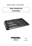

![[IT] Application brochures.qxp:[IT] Kitchen App - tecno](http://vs1.manualzilla.com/store/data/006102550_1-2441a61e303c81eaa28814eb7a6c1f05-150x150.png)