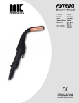
1
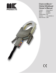
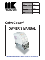
Product Description CobraCooler®
MK Manual Part Number
MK Form Number
NWSA Form Number
091-0542
CBRCLR/OM
550
Effective with Serial Number 03010007
Voltage Rating 100/120/208/240VAC
Printing Date & Revision January 2003
This manual applies to the
250-151
following model numbers
CobraCooler®
OWNER’S MANUAL
16882 ARMSTRONG AVE., IRVINE, CA 92606 TEL (949)863-1234 FAX (949)474-1428
SAFETY CONSIDERATIONS
ELECTRIC ARC WELDING EQUIPMENT
CAUTION : READ BEFORE ATTEMPTING INSTALLATION, OPERATION
OR MAINTENANCE OF THIS EQUIPMENT
1-1 INTRODUCTION
This equipment is intended for ultimate
application by commercial/industrial
users and for operation by persons
trained and experienced in the use and
maintenance of welding equipment.
Operation should not be undertaken
without adequate training in the use of
such equipment. Training is available
from many public and private schools or
similar facilities.
Safe practices in the installation, operation and maintenance of this equipment
requires proper training in the art, a
careful study of the information provided
with the equipment, and the use of
common sense. Rules for safe use
are generally provided by suppliers of
welding power sources, compressed
gas suppliers, and electrode suppliers.
Careful compliance with these rules will
promote safe use of this equipment.
The following Safety Rules cover some
of the more generally found situations.
READ THEM CAREFULLY. In case of
any doubt, obtain qualified help before
proceeding.
1-2 GENERAL PRECAUTIONS
A. Burn Prevention
ELECTRIC ARC WELDING PRODUCES
HIGH INTENSITY HEAT AND ULTRAVIOLET RADIANT ENERGY WHICH
MAY CAUSE SERIOUS AND PERMANENT EYE DAMAGE AND WHICH
MAY DAMAGE ANY EXPOSED SKIN
AREAS.
Wear helmet with safety goggles or
glasses with side shields underneath,
appropriate filter lenses or plates (protected by clear cover glass). This is a
must for welding or cutting (and chipping)
to protect the eyes from radiant energy
and flying metal. Replace cover glass
when broken, pitted, or spattered.
Medical first aid and eye treatment. First
aid facilities and a qualified first aid
person should be available for each shift
unless medical facilities are close by for
immediate treatment of flash burns of
the eyes and skin burns.
Wear protective clothing - leather (or
asbestos) gauntlet gloves, hat, and high
safety-toe shoes. Button shirt collar and
pocket flaps, and wear cuffless trousers
to avoid entry of sparks and slag.
Avoid oily or greasy clothing. A spark
may ignite them.
Flammable hair preparations should not
be used by persons intending to weld
or cut.
Hot metal such as electrode stubs and work
pieces should never be handled without
gloves.
Ear plugs should be worn when working
on overhead or in a confined space. A
hard hat should be worn when others work
overhead.
B. Toxic Fume Prevention
WARNING: The use of this product may
result in exposure to chemicals known
to the State of California to cause cancer
and birth defects or other reproductive
harm.
Adequate ventilation. Severe discomfort,
illness or death can result from fumes,
vapors, heat, or oxygen enrichment or
depletion that welding (or cutting) may
produce. Prevent them with adequate
ventilation. NEVER ventilate with oxygen.
Lead-, cadmium-, zinc-, mercury-, beryllium-bearing and similar materials, when
welded or cut, may produce harmful concentrations of toxic fumes. Adequate local
exhaust ventilation must be used, or each
person in the area, as well as the operator,
must wear an air-supplied respirator. For
beryllium, both must be used.
Metals coated with or containing materials
that emit toxic fumes should not be heated
unless coating is removed form the work
surface, the area is well ventilated, or the
operator wears an air-supplied respirator.
Work in a confined space only while it is
being ventilated and, if necessary, while
wearing an air-supplied respirator.
Causes of fire and explosion are: combustibles reached by the arc, flame,
flying sparks, hot slag, or heated material, misuse of compressed gases and
cylinders, and short circuits.
BE AWARE THAT flying sparks or falling
slag can pass through cracks, along
pipes, through windows or doors, and
through wall or floor openings, out of
sight of the goggled operator. Sparks
can fly many feet.
To prevent fires and explosion:
Keep equipment clean and operable,
free of oil, grease, and (in electrical
parts) of metallic particles that can cause
short circuits.
If combustibles are in area, do NOT weld
or cut. Move the work if practicable,
to an area free of combustibles. Avoid
paint spray rooms, dip tanks, storage
areas, ventilators. If the work cannot
be moved, move combustibles at least
35 feet away, out of reach of sparks and
heat; or protect against ignition with
suitable and snug-fitting, fire-resistant
covers or shields.
Walls touching combustibles on opposite
sides should not be welded on (or cut).
Walls, ceilings, and floor near work
should be protected by heat-resistant
covers or shields.
Fire watcher must be standing by with
suitable fire extinguishing equipment
during and for some time after welding
or cutting if:
Gas leaks in a confined space should be
avoided. Leaked gas in large quantities can
change oxygen concentration dangerously.
Do not bring gas cylinders into a confined
space.
1. Appreciable combustibles (including
building construction) are within 35 feet.
Leaving confined space, shut OFF gas
supply at source to prevent possible accumulation of gases in the space if downstream valves have been accidentally
opened or left open. Check to be sure that
the space is safe before reentering it.
3. Openings (concealed or visible) in
floors or walls within 35 feet may expose
combustibles to sparks.
Vapors from chlorinated solvents can be
decomposed by the heat of the arc (or
flame) to form PHOSGENE, a highly toxic
gas, and other lung and eye irritating products. The ultraviolet (radiant) energy of the
arc can also decompose trichloroethylene
and perchloroethylene vapors to form
phosgene. DO NOT WELD or cut where
solvent vapors can be drawn into the
welding or cutting atmosphere or where
the radiant energy can penetrate to atmospheres containing even minute amounts of
trichloroethylene or perchloroethylene.
C. Fire and Explosion Prevention
2. Appreciable combustibles are further
than 35 feet, but can be ignited by
sparks.
4. Combustibles adjacent to walls, ceilings, roofs, or metal partitions can be
ignited by radiant or conducted heat.
Hot work permit should be obtained
before operation to ensure supervisor’s
approval that adequate precautions have
been taken.
After work is done, check that area is
free of sparks, glowing embers, and
flames.
An empty container that held combustibles, or that can produce flammable or
toxic vapors when heated, must never
be welded on or cut, unless container
has first been cleaned in accordance
with industry standards.
This includes: a thorough steam or
caustic cleaning (or a solvent of water
washing, depending on the combustible’s
solubility), followed by purging and inerting with nitrogen or carbon dioxide, and
using protective equipment.
NEVER DEFACE or alter name, number,
or other markings on a cylinder. It is illegal
and hazardous.
Water-filling just below working level may
substitute for inerting.
Prohibited use. Never use a cylinder or its
contents for other than its intended use,
NEVER as a support or roller.
A container with unknown contents
should be cleaned (see paragraph
above). Do NOT depend on sense of
smell or sight to determine if it is safe
to weld or cut.
Hollow castings or containers must be
vented before welding or cutting. They
can explode.
Explosive atmospheres. NEVER weld or
cut where the air may contain flammable
dust, gas, or liquid vapors (such as
gasoline).
D. Compressed Gas Equipment
The safe handling of compressed gas
equipment is detailed in numerous
industry publications. The following
general rules cover many of the most
common situations.
1. Pressure Regulators
Regulator relief valve is designed to
protect only the regulator from overpressure; it is not intended to protect
any downstream equipment. Provide
such protection with one or more relief
devices.
Never connect a regulator to a cylinder
containing gas other than that for which
the regulator was designed.
Remove faulty regulator from service
immediately for repair (first close cylinder
valve). The following symptoms indicate
a faulty regulator:
Leaks - if gas leaks externally.
Excessive Creep - if delivery pressure
continues to rise with downstream valve
closed.
Faulty Gauge - if gauge pointer does
not move off stop pin when pressurized,
nor returns to stop pin after pressure
release.
Empties: Keep valves closed, replace caps
securely; mark MT; keep them separate
from FULLS, and return promptly.
Locate or secure cylinders so they cannot
be knocked over.
Passageways and work areas. Keep cylinders clear of areas where they may be
stuck.
Transporting cylinders. With a crane, use
a secure support such as a platform or
cradle. Do NOT lift cylinders off the ground
by their valves or caps, or by chains, slings,
or magnets.
Do NOT expose cylinders to excessive
heat, sparks, slag, and flame, etc. that may
cause rupture. Do not allow contents to
exceed 55 degrees C (130 degrees F.)
Cool with water spray where such exposure
exists.
Protect cylinders, particularly valves from
bumps, falls, falling objects, and weather.
Replace caps securely when moving cylinders.
Stuck valve. Do NOT use a hammer or
wrench to open a cylinder valve that cannot
be opened by hand. Notify your supplier.
Mixing gases. NEVER try to mix any gases
in a cylinder.
NEVER refill any cylinder.
Cylinder fittings should never be modified
or exchanged.
3. Hose
Prohibited use. Never use hose other
than that designed for the specified gas.
A general hose identification rule is: red
for fuel gas, green for oxygen, and black
for inert gases.
Use ferrules or clamps designed for the
hose (not ordinary wire or other substitute)
as a binding to connect hoses to fittings.
No copper tubing splices. Use only standard brass fittings to splice hose.
Wipe with a clean, lintless cloth.
Match regulator to cylinder. Before
connecting, check that the regulator label
and cylinder marking agree, and that the
regulator inlet and cylinder outlet match.
NEVER Connect a regulator designed
for a particular gas or gases to a cylinder
containing any other gas.
Tighten connections. When assembling
threaded connections, clean and smooth
seats where necessary. Tighten. If
connection leaks, disassemble, clean,
and retighten, using properly fitting
wrench.
Adapters. Use a CGA adapter (available
from your supplier) between cylinder
and regulator, if one is required. Use
two wrenches to tighten adapter marked
RIGHT and LEFT HAND threads.
Regulator outlet (or hose) connections
may be identified by right hand threads
for oxygen and left hand threads (with
grooved hex on nut or shank) for fuel
gas.
5. Pressurizing Steps:
Drain regulator of residual gas through
suitable vent before opening cylinder
(or manifold valve) by turning adjusting
screw in (clockwise). Draining prevents
excessive compression heat at high
pressure seat by allowing seat to open
on pressurization. Leave adjusting
screw engaged slightly on single-stage
regulators.
Stand to side of regulator while opening
cylinder valve.
Open cylinder valve slowly so that regulator pressure increases slowly. When
gauge is pressurized (gauge reaches
regulator maximum) leave cylinder valve
in following position: for oxygen and inert
gases, open fully to seal stem against
possible leak; for fuel gas, open to less
than one turn to permit quick emergency
shut-off.
Use pressure charts (available from
your supplier) for safe and efficient
recommended pressure settings on
regulators.
Avoid long runs to prevent kinks and abuse.
Suspend hose off ground to keep it from
being run over, stepped on, or otherwise
damaged.
Check for leaks on first pressurization
and regularly thereafter. Brush with
soap solution. Bubbles indicate leaks.
Clean off soapy water after test; dried
soap is combustible.
2. Cylinders
Cylinders must be handled carefully to
prevent leaks and damage to their walls,
valves, or safety devices:
Coil excess hose to prevent kinks and
tangles.
E. User Responsibilities
Protect hose from damage by sharp edges,
and by sparks, slag, and open flame.
Avoid electrical circuit contact with
cylinders including third rails, electrical
wires, or welding circuits. They can
produced short circuit arcs that may lead
to a serious accident. (See 1-3C)
Examine hose regularly for leaks, wear, and
loose connections. Immerse pressured
hose in water; bubbles indicate leaks
Remove leaky or defective equipment
from service immediately for repair. Read
and follow user manual instructions.
ICC or DOT marking must be on each
cylinder. It is an assurance of safety
when the cylinder is properly handled.
4. Proper Connections
Clean cylinder valve outlet of impurities that
may clog orifices and damage seats before
connecting regulator. Except for hydrogen,
crack valve momentarily, pointing outlet
away from people and sources of ignition.
Repair. Do NOT attempt repair. Send
faulty regulators for repair to manufacturer’s designated repair center, where
special techniques and tools are used
by trained personnel.
Identifying gas content. Use only cylinders with name of gas marked on them;
do not rely on color to identify gas
content. Notify supplier if unmarked.
Repair leaky or worn hose by cutting area
out and splicing. Do NOT use tape.
Follow all Safety Rules.
F. Leaving Equipment Unattended
Close gas supply at source and drain
gas.
G. Rope Staging-Support
Rope staging-support should not be
used for welding or cutting operation;
rope may burn.
1-3 ARC WELDING
Comply with precautions in 1-1, 1-2,
and this section. Arc Welding, properly
done, is a safe process, but a careless
operator invites trouble. The equipment
carries high currents at significant voltages. The arc is very bright and hot.
Sparks fly, fumes rise, ultraviolet and
infrared energy radiates, weldments
are hot, and compressed gases may
be used. The wise operator avoids
unnecessary risks and protects himself
and others from accidents.
bustible screens or panels. Allow for free air
circulation, particularly at floor level.
A. Burn Protection
Generator engine exhaust must be vented
to the outside air. Carbon monoxide can
kill.
Comply with precautions in 1-2.
The welding arc is intense and visibly
bright. Its radiation can damage eyes,
penetrate lightweight clothing, reflect
from light-colored surfaces, and burn
the skin and eyes. Skin burns resemble
acute sunburn; those from gas-shielded
arcs are more severe and painful. DON’T
GET BURNED; COMPLY WITH PRECAUTIONS.
1. Protective Clothing
Wear long-sleeve clothing in addition to
gloves, hat, and shoes. As necessary,
use additional protective clothing such
as leather jacket or sleeves, flameproof
apron, and fire-resistant leggings. Avoid
outer garments of untreated cotton.
Bare skin protection. Wear dark, substantial clothing. Button collar to protect
chest and neck, and button pockets to
prevent entry of sparks.
2. Eye and Head Protection
Protect eyes from exposure to arc. Eyes
may be damaged by radiant energy
when exposed to the electric arc, even
when not looking in the direction of the
arc. Never look at an electric arc without
protection.
Welding helmet or shield containing a
filter plate shade no. 12 or denser must
be used when welding. Place over face
before striking arc.
Protect filter plate with a clear cover
plate.
Cracked or broken helmet or shield
should NOT be worn; radiation can be
passed through to cause burns.
Cracked, broken, or loose filter plates
must be replaced IMMEDIATELY.
Replace clear cover plate when broken,
pitted, or spattered.
Flash goggles with side shields MUST
be worn under the helmet to give some
protection to the eyes should the helmet
not be lowered over the face before
an arc is struck. Looking at an arc
momentarily with unprotected eyes
(particularly a high intensity gas-shielded
arc) can cause a retinal burn that may
leave a permanent dark area in the field
of vision.
3. Protection of Nearby Personnel
Enclose the welding area. For production
welding, a separate room or enclosed
bay is best. In open areas, surround the
operation with low-reflective, noncom-
Viewing the weld. Provide face shields for
all persons who will be looking directly
at the weld.
Others working in area. See that all persons
are wearing flash goggles.
Before starting to weld, make sure that
screen flaps or bay doors are closed.
B. Toxic Fume Prevention
Comply with precautions in 1-2B.
C. Fire and Explosion Prevention
Comply with precautions in 1-2C.
Equipment’s rated capacity. Do not overload
arc welding equipment. It may overheat
cables and cause a fire.
Loose cable connections may overheat or
flash and cause afire.
Never strike an arc on a cylinder or other
pressure vessel. It creates a brittle area that
can cause a violent rupture or lead to such
a rupture later under rough handling.
D. Compressed Gas Equipment
Comply with precautions in 1-2D.
E. Shock Prevention
Exposed electrically hot conductors or
other bare metal in the welding circuit, or in
ungrounded, electrically - HOT equipment
can fatally shock a person whose body
becomes a conductor. DO NOT STAND,
SIT, LIE, LEAN ON, OR TOUCH a wet
surface when welding without suitable
protection.
To protect against shock:
Keep body and clothing dry. Never work
in damp area without adequate insulation
against electrical shock. Stay on a dry
duckboard, or rubber mat when dampness
or sweat cannot be avoided. Sweat, sea
water, or moisture between body and
an electrically HOT part - or grounded
metal - reduces the body surface electrical resistance, enabling dangerous and
possibly lethal currents to flow through
the body.
1. Grounding the Equipment
When installing, connect the frames of
each unit such as welding power source,
control, work table, and water circulator to
the building ground. Conductors must be
adequate to carry ground currents safely.
Equipment made electrically HOT by stray
currents may shock, possibly fatally. Do
NOT GROUND to electrical conduit, or to
a pipe carrying ANY gas or a flammable
liquid such as oil or fuel.
Three-phase connection. Check phase
requirement of equipment before installing.
If only three-phase power is available,
connect single-phase equipment to only
two wires of the three-phase line. Do NOT
connect the equipment ground lead to
the third (live) wire, or the equipment will
become electrically HOT - a dangerous
condition that can shock, possibly fatally.
Before welding, check ground for continuity. Be sure conductors are touching
bare metal of equipment frames at connections.
If a line cord with a ground lead is
provided with the equipment for connection to a switch box, connect the ground
lead to the grounded switch box. If a
three-prong plug is added for connection
to a grounded mating receptacle, the
ground lead must be connected to the
ground prong only. If the line cord comes
with a three-prong plug, connect to a
grounded mating receptacle. Never
remove the ground prong from a plug, or
use a plug with a broken ground prong.
2. Connectors
Fully insulated lock-type connectors
should be used to join welding cable
lengths.
3. Cables
Frequently inspect cables for wear,
cracks, and damage. IMMEDIATELY
REPLACE those with excessively worn
or damaged insulation to avoid possibly
lethal shock from bared cable. Cables
with damaged areas may be taped to
give resistance equivalent to original
cable.
Keep cable dry, free of oil and grease,
and protected from hot metal and
sparks.
4. Terminals and Other Exposed
Parts
Terminals and other exposed parts of
electrical units should have insulating
covers secured before operation.
5. Electrode Wire
Electrode wire becomes electrically HOT
when the power switch of gas metal-arc
welding equipment is ON and welding
gun trigger is pressed. Keep hands
and body clear of wire and other HOT
parts.
6. Safety Devices
Safety devices such as interlocks and
circuit breakers should not be disconnected or shunted out.
Before installation, inspection, or service
of equipment, shut OFF all power, and
remove line fuses (or lock or red-tag
switches) to prevent accidental turning
ON of power. Disconnect all cables from
welding power source, and pull all 115
volts line-cord plugs.
Do not open power circuit or change
polarity while welding. If, in an emergency, it must be disconnected, guard
against shock burns or flash from switch
arcing.
Leaving equipment unattended. Always
shut OFF, and disconnect all power to
equipment.
Power disconnect switch must be available near the welding power source.
THIS PAGE INTENTIONALLY BLANK
Table of Contents
INTRODUCTION.............................................................................................. 8
Section 1
TECHNICAL INFORMATION...................................................... 9
Section 2
ELECTRICAL INFORMATION.................................................... 9
Section 3
MECHANICAL INFORMATION .................................................. 9
Section 4
POWER TAPPING ...................................................................... 9
Section 5
CONNECTIONS ........................................................................ 10
5.1 Input Power ....................................................................... 10
5.2 Weldhead........................................................................... 10
5.3 CobraTig® 150 Latches..................................................... 11
Section
6 OPERATION........................................................................... 11
6.1 Coolant .............................................................................. 11
6.2 Thermostats & Alarms ...................................................... 12
6.3 False Alarms and Purging the Line................................. 12
Section 7
ACCESSORIES ........................................................................ 12
7.1 Weldhead Extension Cable.............................................. 12
7.2 Water Hose Assembly ...................................................... 13
Section 8
SPARE PARTS.......................................................................... 13
8.1 Fuse ................................................................................... 13
8.2 Coolant Flow Filter ........................................................... 13
THIS PAGE INTENTIONALLY BLANK
INTRODUCTION
The CobraCooler® is a separate stand-alone unit that conveniently attaches
both mechanically and electrically to the MK welding power supply. The
CobraCooler® provides recirculating coolant to an attached water-cooled
capable orbital weldhead.
The CobraCooler® also provides a status bit to the MK welding power
supply regarding any potential coolant failures such as no coolant flow, overtemperature, or power failure. The CobraCooler® also provides control and
tachometer signal conditioning to the MK welding power supply so that this
system can interface with a variety of different orbital weldheads.
Electrically, the MK welding power supply plugs into the CobraCooler® for
both operational power and control signals to the weldhead and pendant.
The same electrical connections are then provided by the CobraCooler® to
the weldhead, pendant, and AC input making for a clean, safe and portable
electrical interface.
Owner’s Manual - Page 8
Section 1
TECHNICAL INFORMATION
Line Power: 100, 120, 200 230VAC 50/60 HZ, Single Phase ONLY
Reservoir Capacity: 2 qt. / 1.8 l
Coolant Type & Ratio: 3 parts distilled water : 1 part ethylene glycol :
1 tablespoon liquid glycerin
Flow Rate: 0.21 qt/min. / 0.2 l/min. minimum
Section 2
ELECTRICAL INFORMATION
Pump:
Input Power Transformer:
Input Taps:
Printed Circuit Board:
120VAC, 50/60 Hz, 0.50 amps
Auto Transformer, 100 VA
100, 120, 200, 230VAC 50/60 Hz
Coolant fault logic, tachometer feedback
conditioning, home switch logic
AC Power for Cooling Unit: Front panel switchable, power-on LED, front
panel fuse holder
Front Panel Indicators: Power-on: LED, red; Coolant Fault: LED, red &
sonic alert
Section 3
MECHANICAL INFORMATION
Dry Weight:
Height:
Width:
Depth:
Heat Exchanger:
Pump:
Cooling Fans:
21 lbs. / 9.5 Kg
5.5 in. / 14.0 cm
8.5 in. / 21.6 cm
19 in. / 48.3 cm
Fin and Tube, Aluminum
Gear Mesh Pump
105 scfm / 3 std. cu. m/min., 2 each
WARNINGS:
Read and follow instructions prior to performing setup functions.
CAUTIONS:
Read and follow instructions prior to performing operational functions.
Section 4
POWER TAPPING
WARNING
DISCONNECT UNIT FROM ALL POWER SOURCES PRIOR
TO CHANGING POWER TAPS.
ELECTRIC SHOCK CAN KILL
From the top of the CobraCooler®, open the access panel towards the rear
of the unit. Looking down into the unit, locate the power tapping terminal
strip.
Move the jumper and affix to the required input power tap setting.
Change the plug on the end of the cable to suite the required in put power
type.
Owner’s Manual - Page 9
Section 5
CONNECTIONS
5.1 Input Power
The rear panel of the CobraCooler® has as standard a 120VAC type of
power outlet, which allows for the convenient connection of the CobraTig®
150 power supply.
Read the warning below prior to connecting ANY equipment to this power
outlet.
WARNING
THE REAR PANEL OUTLET WILL HAVE THE SAME POWER AS THE INPUT
INTO THE COOLER.
The input power cable is furnished with a standard 15A, 120VAC, three-prong
electrical connector. The power outlet is meant to be used with 120VAC, with
the CobraTig® 150 configured for 120VAC.
See Power Tapping section for instructions on changing configuration for
different input power values.
CAUTION
Adjust the corresponding input power taps in the CobraTig® 150 prior
to connecting to the power outlet on the CobraCooler®.
Otherwise serious electrical damage could occur to the CobraTig® 150.
5.2 Weldhead
The CobraCooler® is designed be used with orbital weldheads supplied
by MK Products, Inc. The operational interface connection between the
CobraCooler® and the CobraTig® 150 is easily performed.
The weldheads have a control cable with a 24 pin connector which plugs
into the CobraCooler® rear panel. Coming from the rear panel of the
CobraCooler® is a short control cable with a 24 pin connector, which plugs
into the rear panel of the CobraTig® 150 and is used to interface the
weldhead to the CobraTig® 150. It is through this interface that error signals
for LOW or NO coolant are transferred into the CobraTig® 150. Once one of
these errors is sensed, the CobraTig® 150 will display the appropriate fault
message, thus notifying the operator of a coolant-type fault.
The other connectors on the rear panel of the CobraCooler® include the
coolant IN/OUT female quick-disconnect connectors. The male connectors
from either the Copperhead™ coolant hoses, the water hose assembly
(P/N 005-0636) or the water-cooled extension cable (P/N 005-0635) can be
attached to this unit.
These coolant connectors are a double-end shut off valve type. This means,
if the cooler is turned on and there is nothing plugged into these connectors,
no fluid will flow out of the connector. Similarly, the connectors on the end of
the weldhead hose work in the same manner. No fluid will flow from the end
of the hose unless it is plugged into the cooler.
Owner’s Manual - Page 10
5.3 CobraTig® 150 Latches
The CobraCooler® easily attaches to the bottom of the CobraTig® 150 using
a four corner-mounted spring-locked latches. These latches are already
mounted to the four outside corners of the CobraCooler®. To the matching
corners of the CobraTig® 150, a screw and shoulder-washer are installed in
place of the existing sheet-metal screw.
Place the CobraTig® 150 on top of the CobraCooler®, so that all sides are
even and flush. Lift the finger handle of the latch and raise the spring up over
the shoulder-washer on the CobraTig® 150. Press down on the finger handle
until the locking spring engages.
Lift the finger handle to test the locking spring. Repeat process on all four
latches.
CAUTION
DO NOT ATTEMPT TO LIFT THE UNIT UNTIL ALL FOUR LATCHES ARE
LOCKED.
To disengage the CobraTig® 150 press on the locking spring and lift the finger
handle until the spring is released from the shoulder-washer.
Section 6
OPERATION
6.1 Coolant
CAUTION
COOLANT MUST BE ADDED PRIOR TO OPERATING.
From the top of the CobraCooler®, open the access panel towards the front
of the unit. Unscrew the fill plug and pour in the recommended mixture of
coolant (see TECHNICAL INFORMATION section for proper mix ratios).
DO NOT SPILL COOLANT INTO THE UNIT.
An electrical short may occur if coolant is spilled into the unit
The Coolant Level Indicator on the front panel of the CobraCooler® shows the
operating level of coolant, without a weldhead. When a weldhead of standard
25’ length is connected, and coolant is run through it, the coolant level will
lower. It is always best to read the coolant level when the unit is operating
and a weldhead is attached.
If the 25 ft. water-cooled extension cable is attached between the
CobraCooler® and the weldhead, again the level of coolant will lower. Once
the extension cable and weldhead are attached, turn on the CobraCooler®
and read the coolant level. Add coolant as necessary.
It is recommended that all coolant be removed from the CobraCooler® prior
to shipping. In order to drain the coolant, locate and remove the drain plug
on the bottom of the cooler. This will allow the coolant to drain from the
reservoir however some coolant may still remain in the internal pump and
circulatory tubing.
Owner’s Manual - Page 11
6.2 Thermostats & Alarms
If there is no coolant or if the coolant level is too low, the CobraTig® 150
will display an error message that indicates a ‘COOLANT FAULT’. This is
an indication to the operator to add more coolant, or check for coolant flow.
If the coolant flow has been obstructed or if one of the connectors has
disconnected, it will also show ‘COOLANT FAULT’.
There are two temperature-sensing thermostats in the CobraCooler®. One
is used to measure the temperature of the coolant as in passes through the
pump and circulatory tubing. If the coolant temperature were to reach 100
degrees Fahrenheit, the cooling fans will turn on and draw air over through
the side panel filter and over the cooling fins.
The other thermostat is located on the side of the reservoir and it measure
the temperature of the coolant in the reservoir. Should the coolant
temperature reach 120 degrees Fahrenheit, again the ‘COOLANT FAULT’ will
appear. This particular fault will not disappear until the coolant temperature
decreases.
At any point a ‘COOLANT FAULT’ appears the sonic alarm from the front
of the CobraCooler® will sound. Once the ‘COOLANT FAULT’ source is
removed, the sonic alarm will turn off.
6.3 False Alarms and Purging the Line
In designing the CobraCooler® to be part of the portable orbital welding
system, the CobraCooler® must also be portable. It is recommended that
when transporting the CobraCooler®, its reservoir tank be emptied of all liquid
contents, then refilled once ready to use again.
However, once the reservoir tank is refilled the CobraCooler® may sound
an audible coolant alarm when powered up, even though the tank is filled
with coolant. Unless there has been some type of physical damage to the
working mechanism or fluid transmission lines in the CobraCooler® or in the
weldhead, this may be a “False Alarm”.
This alarm is caused by trapping an air pocket between the pump and the
‘Coolant Out’ connector which occurs when filling, emptying, and refilling the
reservoir tank. This air pocket cannot be pushed through the lines, thus
keeping the coolant from circulating and signaling a ‘Coolant Fault’.
To cure this problem, locate the ‘Coolant Out’ connector on the rear panel of
the CobraCooler®. With the CobraCooler® turned on, partially disconnect the
weldhead connector, this will release a quick burst of air and a small amount
of water. This will purge the line or the air pocket and start the coolant
travelling through the CobraCooler® and the weldhead, thus eliminating the
alarm. Repeat as necessary.
Section 7
ACCESSORIES
There are two optional accessories available that can be used with the
CobraCooler®.
7.1 Weldhead Extension Cable
One is a 25 ft., water-cooled weldhead extension cable, P/N 005-0635. It
comes complete with all the necessary cabling to adapt the MK orbital
Owner’s Manual - Page 12
weldheads: control cable with 24 pin connector, electrode and ground cables,
inert gas hose and water hose assembly with quick-disconnect connectors.
This extension cable is to mate any of the MK orbital 500X series weldheads
to the CobraCooler®.
7.2 Water Hose Assembly
The second is a 25 ft. water hose assembly, P/N 005-0636. It consists of
two 25 ft. hoses with two male quick-disconnect connectors on one end and
two male double-end shutoff connectors on the other end. This water hose
assembly is to mate any of the MK orbital 600X series weldheads to the
CobraCooler®.
Section 8
SPARE PARTS
8.1 Fuse
WARNING
DISCONNECT UNIT FROM ALL POWER SOURCES PRIOR TO CHANGING
FUSE.
ELECTRIC SHOCK CAN KILL
Located on the front panel of the CobraCooler® is a 0.50 amp BUSS fuse.
If the unit does not turn on with the power switch, check the integrity of
the fuse.
Turn the fuse cap on the front panel and remove fuse. Check fuse using
continuity meter. Replace if necessary.
8.2 Coolant Flow Filter
Periodically, the mesh-screen filter may require cleaning and/or replacement.
It is recommended that all coolant be removed from the CobraCooler® prior
to changing filter. In order to drain the coolant, locate and remove the drain
plug on the bottom of the cooler. The filter can now be removed from the
reservoir and cleaned or replaced.
Owner’s Manual - Page 13
3 YEAR
LIMITED WARRANTY
Effective February 1, 2003
This warranty supersedes all previous MK Products warranties and is
exclusive, with no other guarantees or warranties expressed or implied.
LIMITED WARRANTY - MK Products,Inc.,Irvine,California
warrants that all new and unused equipment furnished by MK
Products is free from defects in workmanship and material as
of the time and place of delivery by MK Products. No warranty
is made by MK Products with respect to trade accessories or
other items manufactured by others. Such trade accessories and
other items are sold subject to the warranties of their respective
manufacturers, if any.
MK Products’ warranty does not apply to components having
normal useful life of less than one (1) year, such as relay points,
wire conduit, tungsten, and welding torch parts that come in
contact with the welding wire, including gas cups, gas cup insulators, and contact tips where failure does not result from defect
in workmanship or material.
MK Products’ shall, exclusively remedy the limited warranty
or any duties with respect to the quality of goods, based upon
the following options:
(1) repair
(2) replacement
(3) where authorized in writing by MK Products, the reasonable
cost of repair or replacement at our Irvine, California plant; or
(4) payment of or credit for the purchase price (less reasonable
depreciation based upon actual use) upon return of the goods at
customer’s risk and expense. Upon receipt of notice of apparent
defect or failure, MK Products shall instruct the claimant on the
warranty claim procedures to be followed.
As a matter of general policy only, MK Products may honor an
original user’s warranty claims on warranted equipment in the
event of failure resulting from a defect within the following periods
from the date of delivery of equipment to the original user:
1. Torches, Weldheads & Water Recirculators................................ 1 year
2. All Other Equipment...................................................................3 years
3. Repairs ..................................................................................... 90 days
Classification of any item into the foregoing categories shall be
at the sole discretion of MK Products. Notification of any failure
must be made in writing within 30 days of such failure.
A copy of the invoice showing the date of sale must accompany
products returned for warranty repair or replacement.
All equipment returned to MK Products for service must be
properly packaged to guard against damage from shipping.
MK Products will not be responsible for any damages resulting
from shipping.
Normal surface transportation charges (both ways) for products
returned for warranty repair or replacement will be borne by MK
Products, except for products sold to foreign markets.
ANY EXPRESS WARRANTY NOT PROVIDED HEREIN AND ANY
IMPLIED WARRANTY, GUARANTY, OR REPRESENTATION AS TO
PERFORMANCE, AND ANY REMEDY FOR BREACH OF CONTRACT
WHICH, BUT FOR THIS PROVISION, MIGHT ARISE BY IMPLICATION, OPERATION OF LAW, CUSTOM OF TRADE, OR COURSE
OF DEALING, INCLUDING ANY IMPLIED WARRANTY OF MERCHANTABILITY OR OF FITNESS FOR PARTICULAR PURPOSE,
WITH RESPECT TO ANY AND ALL EQUIPMENT FURNISHED
BY MK PRODUCTS, IS EXCLUDED AND DISCLAIMED BY MK
PRODUCTS.
EXCEPT AS EXPRESSLY PROVIDED BY MK PRODUCTS IN WRITING, MK PRODUCTS ARE INTENDED FOR ULTIMATE PURCHASE
BY COMMERCIAL/INDUSTRIAL USERS AND FOR OPERATION BY
PERSONS TRAINED AND EXPERIENCED IN THE USE AND MAINTENANCE OF WELDING EQUIPMENT AND NOT FOR CONSUMERS
OR CONSUMER USE. MK PRODUCTS WARRANTIES DO NOT
EXTEND TO, AND NO RE-SELLER IS AUTHORIZED TO EXTEND
MK PRODUCTS’ WARRANTIES TO ANY CONSUMER.
USE OF OTHER THAN GENUINE MK PRODUCTS’
CONSUMABLES, PARTS, AND ACCESSORIES MAY INVALIDATE
YOUR PRODUCT WARRANTY.
16882 Armstrong Ave.
Irvine, CA 92606
Tel (949)863-1234
Fax (949)474-1428
www.mkproducts.com
DATE: February1, 2003
MK PRODUCTS, INC.
16882 ARMSTRONG AVE.
IRVINE,CALIFORNIA 92606
(949) 863-1234 FAX (949) 474-1428