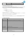
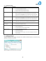
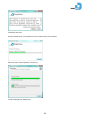
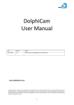
1
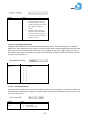
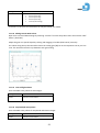
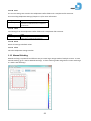
DolphiCam®
User Manual
Date
Version
Author
March 24, 2014
1.2
Jan Olav Endrerud / Eskil Skoglund
www.dolphitech.com
© 2014 DolphiTech. All rights reserved. DolphiTech, the DolphiTech logo, and other DolphiTech marks are owned by DolphiTech and may be
registered. Windows is a trademark of Microsoft Corp., registered in the U.S. and other countries. All other trademarks are the property of
their respective owners. DolphiTech assumes no responsibility for any errors that may appear in this manual. Information contained herein is
subject to change without notice.
1
2
Contents
1.
2.
3.
4.
5.
6.
Overview
1.1
General
1.2
Visualization
1.3
Materials
1.4
DolphiCam
1.4.1
In the Box
1.4.2
Off/Mode Switch
1.4.3
Scan Button
1.4.4
Charging
1.4.5
Installing Software
1.4.6
Connecting and Starting the Camera
1.4.7
Low Battery
1.5
Starting Application
1.6
Software Overview
1.6.1
Calibrating the Camera
1.6.2
Taking Images
1.7
C-Scan
1.8
A-Scan
1.9
B-Scans
1.9.1
Vertical B-Scan
1.9.2
Horizontal B-Scan
1.10
3D View
1.11
DolphiCam Settings & Functionality
1.11.1
Start Gate and End Gate
1.11.2
Amplitude Threshold
1.11.3
Color Focus
1.11.4
Measurement in C-Scan
1.11.5
Depth Measurement in B-Scan
1.11.6
Unit
1.11.7
Material depth
1.11.8
Material Sound of Speed
1.11.9
Transmitting Elements
1.11.10
Analog Gain
1.11.11
Number of Averages
1.11.12
Transmitting Pulse Shape
1.11.13
Time Corrected Gain
1.11.14
Editing Custom Gain Values
1.11.15
Time of flight Palette
1.11.16
Amplitude/B-Scan palette
1.11.17
Amplitude Auto Color Focus
1.11.18
Save
1.11.19
Load
1.11.20
Reset
1.11.21
Close
1.12
Manual Stitching
1.13
Menu Items
1.14
Controlling DolphiCam Settings
Technical Specifications
Troubleshooting
Installing Software
Handling, Safety & Support
5.1
Cleaning the DolphiCam
5.2
Important safety information
5.3
DolphiCam Support
5.4
Disposal and recycling information
License terms
4
4
4
4
5
5
5
5
6
6
6
8
8
8
9
10
11
12
12
12
13
13
14
14
15
16
17
17
18
18
18
18
19
19
20
20
21
21
21
22
23
23
23
23
23
26
27
27
28
28
32
32
32
32
32
33
3
1. Overview
1.1 General
DolphiCam is an advanced ultrasound camera designed for test and inspection of CFRP (Carbon fiber
reinforced plastic) to detect material flaws and defects. The DolphiCam connects to a standard Windows PC
or Windows tablet (not included), making it easy to view and interpret results.
The camera has a transducer with 124 x 124 (15376) elements over the 31x31 mm transducer (16
elements/mm2), capable of detecting very small defects. The transducer pad is silicone-based, enabling dry
coupling on smooth and painted surfaces. Water or contact gel can be used to improve coupling on rougher
surfaces.
1.2 Visualization
DolphiCam supports the following visualization images:
· A-Scan
· B-Scans
o B-Scan Horizontal
o B-Scan Vertical
· C-Scans
o Amplitude
o Time-Of-Flight
· Stitched C-Scans (Amplitude or Time-Of-Flight)
· 3D View
1.3 Materials
The DolphiCam is designed for the following materials:
Material type
CFRP (Carbon fiber reinforced plastic)
Min. approximate
thickness
~ 1 mm
Max. approximate
thickness
~ 8 mm
NOTE: Depending on the exact material variant, material additives, surface treatment and surface structure,
exact minimum and maximum thicknesses may vary.
4
1.4 DolphiCam
1.4.1 In the Box
The DolphiCam comes in a protective case.
Contents:
· DolphiCam with a protective cap
· USB stick with DolphiCam software
· Plexiglas “flower” for demonstration purposes
· Charger (EUR, UK or US standards)
· Spare protective cap
1.4.2 Off/Mode Switch
Turn the camera ON/OFF, and switch between different camera modes.
Position
Off
1
2
3
Calibrate
Description
The Camera is turned OFF
The Camera is ON
Reserved, currently the same as Mode 1
Reserved, currently the same as Mode 1
Camera in Calibration Mode
1.4.3 Scan Button
Start / end scanning. The Scan Button must be clicked (press-and-release) to start scanning video images.
The Scan Button must be clicked again to freeze the images (stop scanning).
The Scan LED is placed in the camera top, oriented towards the operator, just below and to the right of the
Scan Button.
Scanning images
To start scanning
To view a live image stream from the
camera
To end scanning and freeze current
image
Action
Click Scan Button
Leave the scan button
Indication
Scan LED switches from red to green light
Scan LED is green
Click Scan Button again
Scan LED switches from green to red light
5
Make sure that you do not unintentionally leave the camera in scanning mode, as this will drain the battery.
1.4.4 Charging
The DolphiCam is delivered with some power in its internal battery. The camera should be fully charged
with the supplied charger before first use.
Charge DolphiCam with the included USB cable or power adapter. Using damaged cables or chargers, or
charging when moisture is present, can cause electric shock. Power adapters may become warm during
normal use, and prolonged contact may cause injury. Always allow adequate ventilation around power
adapters when using them.
Charging the DolphiCam to full capacity will take up to 5 hours using the charger.
The charging LED is RED when the camera is charging.
The charging LED is GREEN when the camera is fully charged.
NOTE: The DolphiCam charges whenever the camera is connected to an USB port.
NOTE: Make sure the camera is turned OFF using Off/Mode Switch before charging.
1.4.5 Installing Software
See Installing Software (chapter 4).
1.4.6 Connecting and Starting the Camera
When the software installer has finished, connect the camera to the PC by inserting the USB plug.
Turn the camera ON by setting the Off/Mode Switch to “1”.
It is optional to turn the camera ON before it is connected. If the camera is turned OFF when it is connected,
the application waits until a camera is detected.
6
Waiting for camera to be plugged in (USB) and turned on:
DolphiCam is detected and Software is ready:
7
1.4.7 Low Battery
Low battery is indicated in the software by a blinking battery symbol above the C-Scan.
1.5 Starting Application
Start the DolphiCam software by clicking on the icon on your desktop.
Alternatively, start DolphiCam with the name of a DolphiCam configuration file as a parameter:
Example:
C:\Program Files (x86)\DolphiTech\DolphiCam\DolphiCam.exe <mysettings>.dolphicam
You can also double click on the configuration file to start DolphiCam software
1.6 Software Overview
Main window:
8
1.6.1 Calibrating the Camera
Before use, the camera must be calibrated. This will ensure that the ultrasound system is adjusted to the
small variances in the transducer as an effect of microscopic deformations, temperature variations and
other factors.
Calibration is performed towards air.
The Calibration Wizard starts the first time the camera is connected to the PC:
·
·
·
·
·
Point the camera towards air and turn Mode Switch to “Calibrate”.
Click the Scan Button to start scanning.
The calibration sequence will take a few seconds.
Turn Mode Switch back to “1” when the calibration is finished.
Click the Scan Button again to stop scanning.
The camera can be re-calibrated at any time. The calibration is not affected by camera settings.
9
1.6.2 Taking Images
Click the Scan Button to start scanning video.
Click the Scan Button again to freeze image (stop scanning).
When scanning towards air, the result will be something like this:
10
1.7 C-Scan
The C-Scan represents the material as seen from the transducer directly into the material. Two C-Scan
modes are available; Amplitude and Time-of-Flight.
DolphiCam scans in both Amplitude and Time-of-Flight modes and data is recorded independent of which
scan mode the application is in. The user can at any time switch between the two image modes by pressing
Amplitude or Time-of-Flight buttons in the application.
Amplitude
The color in amplitude C-Scan image shows the intensity of the maximum value of your reflected pulse
within your gate.
Time-of-Flight (TOF)
The color in TOF C-Scan shows the depth of the reflected pulse within your gate. Notice the blue back wall
and the different colors of the defect.
Stitch mode
DolphiCam supports a powerful manual stitch mode, making it easy to create multi-tile images covering a
large area.
See 1.12 Error! Reference source not found. for reference.
11
1.8 A-Scan
The A-Scan is presented in the bottom, left part of the application. The A-Scan displays a signal processed
time series of the ultrasound reflection from the material at the intersection between the C-Scan crosshairs,
over the depth of the material.
1.9 B-Scans
The B-Scan represents a cross-section through the material. There are two B-Scans; a vertical B-Scan and a
horizontal B-Scan. The B-Scans are taken at the position of the white lines in the C-Scan image.
To reposition the B-Scans, click inside the C-Scan to move the white cross-hair to a different position. The
cross-hair will reposition itself at the time of the next picture frame.
1.9.1 Vertical B-Scan
The vertical B-Scan is positioned to the left of the C-Scan, and above the A-Scan. The vertical B-Scan displays
a vertical cross-section at the position of the vertical line in the C-Scan image. Notice the relationship to the
color in C-Scan TOF image and the depth of the reflections/defects in your B-Scan.
The start- and end gates can be set by clicking near the gates in the vertical B-Scan, or by modifying the gate
values above (gating is described more in detail in chapter 1.11.1).
12
1.9.2 Horizontal B-Scan
The horizontal B-Scan is positioned to the right of the A-Scan, and below the C-Scan. The horizontal B-Scan
displays a horizontal cross-section at the position of the horizontal line in the C-Scan image.
1.10 3D View
Data from the Time-of-Flight scan is used to give a 3D representation of the material and any defects.
For each time the 3D button in the main window is pressed, a new 3D image is produced. The image can be
zoomed, panned or rotated using the mouse or screen touch.
Screen control:
Mouse wheel
Scroll in or out
Hold left mouse button
Pan
Hold right mouse button
Rotate
Cube in lower, right corner; U, D
View from upside or bottom
Cube in lower, right corner; F, B
View from front or back
Cube in lower, right corner; L, R
View from left or right
13
1.11 DolphiCam Settings & Functionality
1.11.1 Start Gate and End Gate
Setting your gate enables you to study a specific depth of your material.
The start and end gate can be set between -0.38 mm and 8.06 mm.
The gates can be set in different ways:
· Entering a specific depth in the Start Gate and End Gate fields respectively, or
· Adjusting the gates using the + (plus) and – (minus) buttons on each side of the Gate Value field, or
· Click the mouse in the vertical B-Scan to get your desired gate. If the cursor is closest to the Start
Gate line, the Start Gate value will be adjusted. If the cursor is closest to the End Gate line, the End
Gate value will be adjusted.
NOTE:
· The gate values will take effect in your next image.
· Amplitude image and Time-of-Flight image have separate Start Gate and End Gate settings.
14
1.11.2 Amplitude Threshold
The blue horizontal line in the A-Scan sets the amplitude threshold (0-100%). All signal amplitudes below
the threshold will be ignored:
For C-Scan Amplitude and B-Scan images:
· All signal amplitudes below the amplitude threshold will be interpreted as the same value as the
threshold value.
For C-Scan TOF and 3D image:
· All signal amplitudes below the amplitude threshold will be ignored and given the color value of the
grayscale color palette (GrayWhite).
15
1.11.3 Color Focus
By default, the DolphiCam will spread colors in the palette evenly over 0-100% in Amplitude Images and
over the complete depth in TOF image.
By using the Color Focus Slide Bar to the right of the C-Scan, it is possible to focus the colors in a smaller part
of the color scale. The color focus is possible for both amplitude images (%) and Time of Flight images
(depth – mm/inches/mils).
There is a top slider and bottom slider to control the color focus. You can also move the selected color focus
by click-and-hold in between the top and bottom slider and drag your color focus area up and down.
Time-of-Flight Color Focus
In Time-of-Flight image, all colors above the top slider will be given the color of the top slider, and all values
below the bottom slider will be given the value of the bottom slider.
Amplitude Color Focus
In all amplitude images (C-Scan and B-Scan), all colors above the top slider will be given the color of the top
slider, and all values below the bottom slider will be given the value of the bottom slider.
16
1.11.4 Measurement in C-Scan
By right-clicking drag-and-hold in the C-Scan, you can measure the size of your defect. This is useful for
measuring the size of material defects. You can add up to 10 measure lines.
1.11.5 Depth Measurement in B-Scan
By right-clicking drag-and-hold in any of the B-scans, you can measure the depth and the size of the defect.
This is useful for measuring the size of material defects. You can add up to 10 measure lines.
17
1.11.6 Unit
Sets the units for the system.
Setting
Unit
Input
Select from dropdown list:
·
Millimeters (mm) - default
·
Inches (in)
·
Mils (1/1000 inches)
1.11.7 Material depth
Limits the material thickness to be examined.
Sets the depth scales for A-Scan and B-Scan.
Also, this affects the color distribution in C-Scan TOF. It is recommended to set the Material Depth to just
include your back wall echo, as this takes advantage of all the colors in your palette.
Setting
Material depth
Input
Use slider; select an approximate material
thickness in the range:
·
1.1 – 8.1 Mm, or
·
0.044 – 0.317 Inches, or
·
44 – 317 Mils
1.11.8 Material Sound of Speed
Sound of speed in m/s or ft/s for the material.
Setting
Material sound of
speed
Input
Set value:
·
Enter numeric value (default=3000
m/s) for the material to be examined
1.11.9 Transmitting Elements
The transmitting energy can be adjusted using different number of transmitting elements (1-8).
Transmitting a higher number of elements gives higher energy and focus at higher depths.
Transmitting fewer elements gives less energy but might give higher resolution for very thin composite
materials.
Note that the transmitting elements are aligned next to each other along an array in the vertical direction.
18
The default number of transmitting elements is 4.
Setting
Transmitting
elements
Input
Select from dropdown list:
·
1
·
2
·
3
·
4 - default
·
5
·
6
·
7
·
8
1.11.10 Analog Gain
Easy analog gain control to raise/lower the gain in receiver electronics. When TCG (time corrected gain), is
enabled, the analog gain control will raise/lower the complete TCG profile.
Setting
Analog Gain
Input
Control with +/- buttons:
·
Range 1.3 dB to 65,1 dB
(Default: Different default gain
adapted for each transmitting
pulse shape)
1.11.11 Number of Averages
Noise reduction strategy. You can choose how many averages the system runs on each transducer element.
A lower number of averages gives you slightly poorer Signal-to-Nose ratio, but a higher frame rate.
19
Setting
Number of averages
Input
Select from dropdown list:
·
2: Noise reduction based on 2
ultrasound samples. The noise
reduction is good, but the frame
rate is higher; 4 images per
second.
·
4 – Default: Noise reduction
based on 4 ultrasound samples.
This noise reduction is higher, at
the cost of a lower frame rate; 2
images per second
1.11.12 Transmitting Pulse Shape
DolphiCam has 8 different user selectable transmitting pulse shapes. Each pulse shape has an adapted
digital filter. The combination of the nature of the pulse shape and the adapted digital filtering makes each
pulse special in the sense of different parameters, such as Signal-to-Noise ratio, pulse length, etc. Each of
the different pulse shapes has different qualities that makes them suitable for different material, material
thickness, size of defect, etc.
Setting
Transmitting Pulse
Shape
Input
Select from dropdown list:
·
1 - default
·
2
·
3
·
4
·
5
·
6
·
7
·
8
1.11.13 Time Corrected Gain
Gain adjustment (analog) as a function of time/depth. With time corrected gain, it is possible to adjust the
amplification (or dampening) of signals at a specific depth. The system has 5 different preset ramp-ups and
can also be set custom.
Setting
Time Corrected
Gain
Input
Select from dropdown list:
·
Off - default
·
Preset 1 (view only)
20
Setting
Input
·
·
·
·
·
Preset 2 (view only)
Preset 3 (view only)
Preset 4 (view only)
Preset 5 (view only)
Custom (edit settings)
In Preset 1-5, the Time Corrected Gain can only be viewed, not edited.
1.11.14 Editing Custom Gain Values
Open Time Corrected Gain Settings by selecting “Custom” from the drop-down menu and click the “Edit”
button. (Click Edit).
Adjust the gain at a specific depth by clicking and dragging its handle (blue button) vertically.
The values along the top horizontal bar shows the analog gain [dB] set at the respective time in you’re Ascan. The TCG time interval is 1µs between each gain setting.
1.11.15 Time of flight Palette
User selectable color palette for TOF images.
Setting
Time of flight
Palette
Input
Select from dropdown list a color palette.
Default is JetColorPalette
1.11.16 Amplitude/B-Scan palette
User selectable color palette for Amplitude and B-Scan images.
Setting
Amplitude/B-Scan
palette
Input
Select from dropdown list a color palette.
Default is JetColorPalette
21
1.11.17 Amplitude Auto Color Focus
Automatically calculate and apply the complete color spectrum in the image. If this option is selected, user
selected color focus is not possible – and the color focus selector is removed from the edge of the C-Scan.
Setting
Amplitude auto
color focus
Input
Select from dropdown list:
·
On
·
Off – default
22
1.11.18 Save
The current settings are stored to the DolphiCam Profiles folder with a .DolphiCam file extension.
See Controlling DolphiCam Settings (chapter 1.14) for more information.
Setting
Save settings…
Input
The current settings are stored to the
DolphiCam Profiles folder with a .DolphiCam
file extension.
1.11.19 Load
Load settings from the DolphiCam Profiles folder with a .DolphiCam file extension.
Setting
Load settings…
Input
Load settings from the DolphiCam Profiles
folder with a .DolphiCam file extension.
1.11.20 Reset
Resets all settings to default values.
1.11.21 Close
Close the DolphiCam settings window.
1.12 Manual Stitching
Manual stitching is a powerful and effective way to create larger images made of multiple C-Scans. To start
manual stitching, go to <Tools><Manual Stitching>. To leave stitching mode and go back to main window go
to <Tools><Exit Stitching>.
23
One way of using stitching mode, is to simply start taking your first image and click one of the arrows
around your C-scan to continue stitching in the direction you choose. Each tile in the stitch is as big as the
transducer front (31x31mm). The tiles overlap by 6mm, which means that the tiles (center-to-center) are
25mm (~1 inch) apart. The camera should be oriented in the same angle for each image taken (this is
relatively easy). If your C-scan images are not perfectly aligned, simply move them around with your mouse
or arrows on your keyboard (view top image below) You can also control the overlap on images by rightclicking and selecting “Bring to front”, or “Send to back” (view bottom image below).
24
When inspecting a larger predefined area, the easiest way to stich is to use the sequence mode. First you
click the arrows on your stitching image until you have covered the desired area. Then simply click on the
sequence button , and your sequence will displayed for you. Whenever you click to freeze your C-scan
image, the image moves to the next tile in your stitch. To view your complete scan, increase the number of
tiles in your view by clicking on the +/- button or enter the number of tiles desired.
Click on the measure line button
to enable measure lines. Right click on your mouse and drag to add
your measure lines (while measure lines are enabled, the “Bring to Front/Send to back” function is
disabled).
To reset your stitching procedure, click the reset button
your view, measure lines, and sequence.
25
. All your images will then be deleted, as well as
Stitching tip:
Since the tiles are located 25mm (~1 inch) apart, you can prepare your measurement by marking your
material for inspection with dots 25mm (~1 inch) apart in all directions, either by using a ruler or f.ex. a
silicon sheet with pre-cut holes in it.
Using these predefined marks, you can easily aim at them using one of the lines in DolphiCam housing.
Doing this really simplifies and speed up your inspection.
1.13 Menu Items
Menu
File menu
Item
Save Images
Description
Creates a ZIP file containing:
·
TimeOfFlight.[png|tif|bmp|jpg]
·
AScan.[png|tif|bmp|jpg]
·
BScanVertical.[png|tif|bmp|jpg]
·
BScanHorizontal.[png|tif|bmp|jpg]
·
CameraSettings.txt
Tools menu
Take Screenshot
Export C-scan to NDT-kit
DolphiCam settings…
Manual Stitching…
User Guide (PDF)
Creates a [png|tif|bmp|jpg] image of main window.
Export C-scan to NDT-kit file format
Open DolphiCam settings (page 14)
Enters manual stitching mode (page 23)
Opens the User Guide (PDF format).
Help menu
26
About DolphiCam…
Support…
Display serial number, camera description, software version,
firmware version, hardware version, and camera type.
Opens the link to DolphiTech support page.
1.14 Controlling DolphiCam Settings
DolphiCam settings are configured using Tools > DolphiCam Settings. Settings are stored in separate setting
files. This makes it easy to handle different settings for different NDT scenarios. Some settings are
controlled in the main window; amplitude threshold, gate-values, color focus, C-Scan image selection.
·
·
Save settings…
o Save settings to a settings file
Load settings…
o Load settings from a settings file
Setting files are stored in the Profiles folder, located in
C:\Users\Public\Documents\DolphiCam\Profiles folder (Windows 7), and have a .DolphiCam extension.
DolphiCam can be started with a setting file as a startup parameter:
<path to dolphicam.exe>\dolphicam.exe <.DolphiCam file>
Example: Start DolphiCam with the settings file impact01.DolphiCam located in the default setting folder:
C:\Users\Public\Documents\DolphiCam\Profiles\DolphiCam.exe impact01.DolphiCam
2. Technical Specifications
Dimensions
115 x 170 x 68 mm / 4.5” x 6.7” x 2.7”
Weight
0.470 kg / 1.04 lbs.
Detection and inspection
CFRP composite materials < 8 mm thickness and 31 mm x 31 mm capture size
Transducer
124x124 elements, 16 elements/mm2 over 31 x 31 mm
Power
Re-chargeable Li-ion battery
Charging
Charger or USB
Battery life
≈ 5 hours of continuous video scanning
Communication
USB 1.1 / 2.0
Operating temperature
0˚ to 40˚ C / 32˚ to 104˚ F
Storage temperature
-20˚ to 65˚ C / -4˚ to 149˚ F
Ingress Protection
IP54 (Protection for dust and splashing water from all sides)
EMC
EN 61326:1997+A1:1998+A2:2000+A3:2003 / FCC Subpart 15
Electrical safety
EN/IEC 61010-1:2001
Software and Display
PC and Tablet devices running Windows XP SP3 and later or Windows 8.
PC/tablet is not included.
Automatic firmware and software updates.
27
3. Troubleshooting
Problem
Camera will not work
Resolution
·
Make sure the camera is connected to the USB port.
·
Try to restart the DolphiCam software.
·
Try to connect/reconnect the camera to the PC.
·
Charge the camera using the DolphiCam charger.
The camera gets warm
·
·
·
Low battery life
·
·
The camera will get warm during normal operation.
Make sure that the camera isn’t scanning images when you don’t intend to.
Visually check that the Scan LED is out or red before you put the camera away.
Always turn the camera OFF when you don’t use it, or it is stored in the case.
Make sure that the camera isn’t scanning images when you don’t intend to.
Visually check that the Scan LED is out or red before you put the camera away.
Always turn the camera OFF when you don’t use it, or it is stored in the case.
DolphiCam will not work
on the Windows emulator
on Mac, Linux or similar
·
DolphiCam is only supported on native MS Windows systems. DolphiTech gives
no guarantees, or give any support on MS Windows emulating software.
Camera housing or cables
are damaged
·
·
Do not use the camera.
Send it back to the supplier for repair
Noisy or unclear images
·
·
·
Make sure the object is clean.
Clean the transducer pad.
Try using contact gel or water to improve coupling.
Noise in the picture
·
·
·
·
Tune the scanning and/or camera setting.
Use coupling water or gel.
Clean the Transducer Pad
Check Transducer Pad for damages. A camera with a damaged Transducer Pad
must be repaired.
4. Installing Software
Insert the USB stick in your computer. Navigate to the USB disk in Windows Explorer, and start the setup
application. Follow the instructions.
Read, and agree to the license terms. Click Install.
28
Installation will start.
Setup will determine if an updated version of .NET needs to be installed.
Microsoft .NET will be updated, if necessary.
Install the DolphiCam USB drivers.
29
Follow the Device Driver Installation Wizard.
Complete the Device Driver Installation Wizard.
Close DolphiCam setup. Restart the computer if asked to do so.
30
Setup is complete!
31
5. Handling, Safety & Support
5.1 Cleaning the DolphiCam
Cleaning the DolphiCam housing Clean DolphiCam immediately if it comes in contact with anything that may cause
stains—such as dirt, ink, paint or oil. Turn Off the DolphiCam and disconnect it from the PC. Wipe it off/clean it with a
soft, lint-free cloth moistened with mild soap water. Remove the protective cap, and carefully clean around the
Transducer Pad. Do not clean the silicone directly, as it will be cleaned separately. Do not use solvents of any kind.
Avoid getting dirt into openings. Don’t use aggressive cleaning products or compressed air. Put the protective cap back
on.
Cleaning the Transducer Turn the DolphiCam Off, and disconnect it from the PC. Remove the protective cap. Clean
the DolphiCam housing first, see above. Put a drop of mild dishwasher soap on the transducer pad and rub it gently
with the tip of your finger. Dip your finger in water and rub on pad until soap is gone. Make sure the Transducer Pad
isn’t scratched or damaged. Moist a soft, lint-free cloth with water and wipe off excessive water carefully. Put the
protective cap back on.
5.2 Important safety information
Repairing Don’t open DolphiCam and don’t attempt to repair DolphiCam by yourself. Disassembling DolphiCam may
cause injury to you or damage to DolphiCam, and will void all guarantee. If DolphiCam is damaged or malfunctions,
contact DolphiTech or a DolphiTech Authorized Service Provider. You can find more information about getting service
at www.dolphitech.com.
Explosive atmospheres Do not charge or use DolphiCam in any area with a potentially explosive
atmosphere, such as at a fueling area, or in areas where the air contains chemicals or particles (such as
grain, dust, or metal powders). Obey all signs and instructions.
Battery Don’t attempt to replace the DolphiCam battery yourself—you may damage the battery, which could cause
overheating and injury. The lithium-ion battery in DolphiCam should be replaced only by DolphiTech or a DolphiTech
Authorized Service Provider, and must be recycled or disposed of separately from household waste. Don’t incinerate
the battery. For information about battery recycling and replacement, go to www.dolphitech.com.
Handling Handle DolphiCam with care. It is made of metal and plastic and has sensitive electronic components inside.
DolphiCam can be damaged if dropped, burned, punctured, or crushed or if it comes in contact with excessive amounts
of liquid. Don’t use a damaged DolphiCam, such as one with a cracked housing, as it may cause injury. Keep the
protective cap in place whenever the camera is not taking pictures. Store and transport the camera in the flight case.
Using connectors, ports, and buttons Never force a connector into a port or apply excessive pressure to a button,
because this may cause damage that is not covered under the warranty. If the connector and port don’t join with
reasonable ease, they probably don’t match. Check for obstructions and make sure that the connector matches the
port and that you have positioned the connector correctly in relation to the port.
Operating temperature DolphiCam is designed to work in ambient temperatures between 32° and 104° F (0° and
40° C) and stored in temperatures between -4° and 149° F (-20° and 65° C). DolphiCam can be damaged and battery life
shortened if stored or operated outside of these temperature ranges. Avoid exposing DolphiCam to dramatic changes
in temperature or humidity. When you’re using DolphiCam or charging the battery, it is normal for DolphiCam to get
warm.
Choking hazard Some DolphiCam accessories may present a choking hazard to small children. Keep these accessories
away from small children.
5.3 DolphiCam Support
Comprehensive support information is available online at www.dolphitech.com.
5.4 Disposal and recycling information
Your DolphiCam must be disposed of properly according to local laws and regulations. Because it contains a battery,
DolphiCam must be disposed of separately from household waste. When your DolphiCam reaches its end of life,
contact DolphiTech or your local authorities to learn about recycling options.
32
Battery replacement: The lithium-ion battery in DolphiCam should be replaced only by DolphiTech or a DolphiTech
Authorized Service Provider, and must be recycled or disposed of separately from household waste. For information
about battery recycling and replacement, go to www.dolphitech.com/support.
European Union—Disposal Information
The symbol above means that according to local laws and regulations your product and/or its battery shall be disposed
of separately from household waste. When this product reaches its end of life, take it to a collection point designated
by local authorities. The separate collection and recycling of your product and/or its battery at the time of disposal will
help conserve natural resources and ensure that it is recycled in a manner that protects human health and the
environment.
6. License terms
View License terms in “License Information” link in “About DolphiCam” window.
DolphiTech AS
Building 1, Raufoss Industrial Park
N-2830 Raufoss
Norway
Email: [email protected]
Web: www.dolphitech.com
33