1
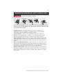
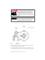
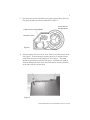
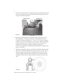
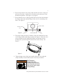
Pump and Sand Filter System Installation and User’s Guide IMPORTANT SAFETY INSTRUCTIONS READ AND FOLLOW ALL INSTRUCTIONS SAVE THESE INSTRUCTIONS Pump and Sand Filter System Installation and User’s Guide Technical Support Sanford, North Carolina (8 A.M. to 5 P.M. ET) Moorpark, California (8 A.M. to 5 P.M. PT) Phone: (800) 831-7133 Fax (800) 284-4151 Web sites: visit www.pentairpool.com and staritepool.com Contents Warnings and Important Safety Precautions .................................................. i Section 1: Pump and Sand Filter System Overview .................................... 1 Valve Position and Water Flow Directions .......................................................... 2 Section 2: Installation .......................................................................................... 3 Section 3: Operation and Maintenance ........................................................... 10 Initial Start-Up ........................................................................................................... 10 Maintenance ............................................................................................................. 11 Cleaning .................................................................................................................... 12 Filter Backwash Procedure .................................................................................... 13 Chemical Cleaning ..................................................................................................14 Replacement of Valve Top and Diverter Assembly ............................................ 15 Winterizing the System ........................................................................................... 16 Section 4: Troubleshooting ................................................................................. 17 Section 5: Technical Data and Replacement Parts ...................................... 17 © 2009 Pentair Water Pool and Spa, Inc. All rights reserved This document is subject to change without notice 1620 Hawkins Ave., Sanford, NC 27330 • (919) 566-8000 10951 West Los Angeles Ave., Moorpark, CA 93021 • (805) 553-5000 Pentair Water Pool and Spa® is a registered trademark of Pentair Water Pool and Spa, Inc. and/or its affiliated companies in the United States and/or other countries. Filter-Cleanse™ is a trademark of Advantis Technologies Inc. and Klean It® is a registered trademark of BioLab, Inc. Unless noted, names and brands of others that may be used in this document are not used to indicate an affiliation or endorsement between the proprietors of these names and brands and Pentair Water Pool and Spa, Inc. Those names and brands may be the trademarks or registered trademarks of those parties or others. P/N 152007 Rev A - 12/09/09 Pump and Sand Filter System Installation and User ’s Guide i WARNINGS AND IMPORTANT SAFETY PRECAUTIONS SERIOUS BODILY INJURY OR DEATH CAN RESULT IF THIS PUMP AND SAND FILTER IS NOT INSTALLED AND USED CORRECTLY. INSTALLERS, POOL OPERATORS AND POOL OWNERS MUST READ THESE WARNINGS AND ALL INSTRUCTIONS BEFORE USING THIS PUMP AND SAND FILTER. This pump and sand filter system is intended for use in swimming pool applications. Most states and local codes regulate the construction, installation, and operation of public pools and spas, and the construction of residential pools and spas. It is important to comply with these codes, many of which directly regulate the installation and use of this product. Consult your local building and health codes for more information. IMPORTANT NOTICE - Attention Installer: This Installation and User’s Guide (“Guide”) contains important information about the installation, operation and safe use of this pump and sand filter. This Guide should be given to the owner and/or operator of this equipment. Before installing this product, read and follow all warning notices and instructions in this Guide. Failure to follow warnings and instructions can result in severe injury, death, or property damage. Call (800) 831-7133 for additional free copies of these instructions. Please refer to www.pentair.com for more information related to these products. Water temperature in excess of 100° F (37.7° C) may be hazardous to your health. Prolonged immersion in hot water may induce hyperthermia. Hyperthermia occurs when the internal temperature of the body reaches a level several degrees above normal body temperature of 98.6° F (37° C.). Effects of hyperthermia include: (1) Unawareness of impending danger. (2) Failure to perceive heat. (3) Failure to recognize the need to leave the spa. (4) Physical inability to exit the spa. (5) Fetal damage in pregnant women. (6) Unconsciousness resulting in danger of drowning. The use of alcohol, drugs, or medication can greatly increase the risk of fatal hyperthermia in hot tubs and spas. To reduce the risk of injury, do not permit children to use or operate this pump and sand filter. When setting up pool water turnovers or flow rates the operator must consider local codes governing turnover as well as disinfectant feed ratios. DO NOT increase pump size; this may increase the flow rate through the system and exceed the maximum flow rate stated on the drain cover. If this pump and sand filter is intended for use in other than single-family dwellings, a clearly labeled emergency switch shall be provided as part of the installation. The switch shall be readily accessible to the occupants and shall be installed at least 5 feet (1.52 m) away, adjacent to, and within sight of, this pump and sand filter system. Pump and Sand Filter System Installation and User’s Guide ii WARNINGS AND IMPORTANT SAFETY PRECAUTIONS High Pressure from the sand filter can cause severe injury or major property damage due to tank separation. Release all pressure and read instructions before working on the sand filter. If the filter clamp is adjusted under pressure, the tank can separate, causing serious injury or major property damage. BEFORE WORKING ON FILTER! (1) Stop pump. (2) Open air release valve. (3) Release all pressure from system. RISK OF ELECTRICAL SHOCK OR ELECTROCUTION: PUMPS REQUIRE HIGH VOLTAGE WHICH CAN SHOCK, BURN, OR CAUSE DEATH. BEFORE WORKING ON PUMP! Always disconnect power to the pool pump at the circuit breaker before servicing the pump. Failure to do so could result in death or serious injury to service person, pool users or others due to electric shock. A pool or spa pump must be installed by a qualified pool and spa service professional in accordance with the National Electrical Code and all applicable local codes and ordinances. Improper installation may create an electrical hazard which could result in death or serious injury to pool users, installers, or others due to electrical shock, and may also cause damage to property. Pumps improperly sized or installed or used in applications other than for which the pump was intended can result in serious personal injury or death. These risks may include but not be limited to electric shock, fire, flooding, suction entrapment or serious injury or property damage caused by a structural failure of the pump or other system component. Never exceed the maximum stated pump flow rating. Only use a pumping system rated for the corresponding flow. FAILURE TO DO SO CAN RESULT IN HAIR OR BODY ENTRAPMENT WHICH CAN CAUSE SERIOUS PERSONAL INJURY OR DEATH. If in doubt about the rating of your system, consult a qualified pool service professional. Pumps are not a substitute for properly installed and secured pool drain covers. An ANSI/ASME A112.19.8 approved antientrapment drain cover must be used for each drain. Pools and spas should utilize a minimum of two drains per pump. Regularly inspect all covers for cracks, damage and advanced weathering. If a cover becomes loose, cracked, damaged, broken or is missing, close the pool or spa immediately, shut off the pump, post a notice and keep the pool or spa closed until an appropriate VGB 2008 certified cover is properly installed. Covers deteriorate over time due to exposure to sunlight and pool chemicals. This cover must be replaced within seven (7) years from installation (or earlier if the cover becomes damaged in any way). Pump and Sand Filter System Installation and User’s Guide iii WARNINGS AND IMPORTANT SAFETY PRECAUTIONS SUCTION ENTRAPMENT HAZARD F Pool and spa pumps move large volumes of water, which can pose extreme danger if a person’s hair comes in close proximity to a drain that is not the proper size for the pump or pumps. Hair Entanglement – When the hair tangles or knots in the drain cover, trapping the swimmer underwater. This hazard is present when the flow rating of the cover is too small for the pump or pumps. Limb Entrapment – When a limb is sucked or inserted into an opening resulting in a mechanical bind or swelling. This hazard is present when a drain cover is missing, broken, loose, cracked or not properly secured. Body Entrapment – When a portion of the body is held against the drain cover trapping the swimmer underwater. This hazard is present when the drain cover is missing, broken or the cover flow rating is not high enough for the pump or pumps. Evisceration/Disembowelment – When a person sits on an open pool (particularly a child wading pool) or spa outlet and suction is applied directly to the intestines, causing severe intestinal damage. This hazard is present when the drain cover is missing, loose, cracked, or not properly secured. Mechanical Entrapment – When jewelry, swimsuit, hair decorations, finger, toe or knuckle is caught in an opening of an outlet or drain cover. This hazard is present when the drain cover is missing, broken, loose, cracked, or not prop erly secured. Pump and Sand Filter System Installation and User’s Guide iv WARNINGS AND IMPORTANT SAFETY PRECAUTIONS The Virginia Graeme Baker Pool and Spa Safety Act imposes certain new requirements on owners and operators of swimming pools and spas. Pools or spas constructed on or after December 20, 2008, shall utilize: (A) No submerged suction outlets, a gravity drainage system with ASME/ANSI cover(s), one or more unblockable outlets; or (B) A multiple main drain system without isolation capability with suction outlet covers that meet ASME/ANSI A112.19.8 Suction Fittings for Use in Swimming Pools, Wading Pools, Spas, and Hot Tubs and either: (i) A safety vacuum release system (SVRS) meeting ASME/ANSI A112.19.17 Manufactured Safety Vacuum Release Systems (SVRS) for Residential and Commercial Swimming Pool, Spa, Hot Tub, and Wading Pool Suction Systems and/or ASTM F2387 Standard Specification for Manufactured Safety Vacuum Release Systems (SVRS) for Swimming Pools, Spas and Hot Tubs or (ii) A properly designed and tested suction-limiting vent system or (iii) An automatic pump shut-off system. Pools and spas constructed prior to December 20, 2008, with a single submerged suction outlet shall use a suction outlet cover that meets ASME/ANSI A112.19.8 and either: (A) A multiple main drain system without isolation capability, or (B) A safety vacuum release system (SVRS) meeting ASME/ANSI A112.19.17 and/or ASTM F2387, or (C) A properly designed and tested suction-limiting vent system, or (D) An automatic pump shut-off system, or (E) Disabled submerged outlets, or (F) Suction outlets shall be reconfigured into return inlets. For information about the Virginia Graeme Baker Pool and Spa Safety Act, contact the Consumer Product Safety Commission at (301) 5047908 or visit www.cpsc.gov. NOTE: Always turn off all power to the pool pump before installing the cover or working on any suction outlet. Two Speed Pump Controls Notice (Title 20 Compliance) Please read the following important Safety Instructions. When using two-speed pumps manufactured on or after January 1, 2008, the pump's default circulation speed MUST be set to the LOWEST SPEED, with a high speed override capability being for a temporary period not to exceed one normal cycle, or two hours, whichever is less. Pump and Sand Filter System Installation and User’s Guide 1 Section 1 Pump and Sand Filter System Overview This system operates under pressure and if assembled improperly or operated with air in the water circulation system it can separate and result in an accident causing serious bodily injury. A warning label has been affixed to the filter and should not be removed. Keep safety labels in good condition and replace if missing or illegible. (For free labels call, (919)-774-4151). Pumps and filters should never be tested or subjected to air or gas under pressure. All gases are compressible and under pressure create a danger. Serious bodily injury or property damage could occur if the pump or filter is subjected to air or gas pressure. The system consists primarily of a centrifugal pump, a high rate sand filter with control valve, a connecting hose and a mounting base. Your centrifugal pump is driven by an electric motor. The motor is directly attached to the pump impeller. As the electric motor turns it causes the impeller to turn and this causes the water to flow. The water flows into the hair and lint pot inlet and through the basket assembly to prestrain large particles. The flow then enters the center of the pump housing. The flow goes through the impeller into the stationary diffuser, out the pump discharge port, through the connecting hose and into the filter control valve. Dirt is collected in the filter as the water flows through the control valve at the top of the filter and is directed downward onto the top surface of the filter sand bed. The dirt is collected in the sand bed and the clean water flows through the lower piping at the bottom of the filter up through the center pipe into the control valve at the top of the filter. Clean water then returns through the piping system to the pool. The pressure will rise and the flow to the pool will be lowered as the dirt is collected in the filter. Eventually, the filter will become so plugged with dirt that it will be necessary to perform the backwash procedure. It is important to know when to backwash the filter. For backwashing information, see page 12 and 13. The six (6) operating position and one (1) “Winterize” position valve is designed to provide all the necessary positions required to operate, maintain, troubleshoot and service your sand filter. Air entering the filter and a valve clamp not closed properly can cause the valve to separate and could cause serious bodily injury and/or property damage. To prevent equipment damage and possible injury, always turn pump off before changing valve position. Pump and Sand Filter System Installation and User’s Guide 2 This filter operates under high pressure. When any part of the circulating system (e.g., clamp, pump, filter, valves, etc.) is serviced, air can enter the system and become pressurized. Pressurized air can cause the lid or control valve to separate which may result in serious injury, death, or property damage. To avoid this potential hazard, follow these instructions. 1. Before repositioning valves and before beginning the assembly, disassembly, or adjustment of the clamp or any other service of the circulating system: (a) Turn the pump off and shut off any automatic controls to ensure the system is not inadvertently started during the servicing; (b) Open manual air relief valve; (c) Wait until all pressure is relieved, pressure gauge must read zero (0). 2. Whenever installing the filter clamp, follow the filter valve and clamp installation instructions exactly. 3. Once service on the circulating system is complete, follow system restart instructions exactly. 4. Maintain circulation system properly. Replace worn or damaged parts immediately (e.g., clamp, pressure gauge, relief valve, o-rings, etc.). 5. Be sure that the filter is properly mounted and positioned according to instructions provided. Valve Position and Water Flow Directions FILTER: From pump, through valve, downward through filter sand bed, up through center pipe to valve return port, and back to the pool for normal filter action and vacuuming pool through filter. BACKWASH: From pump, through valve, down through center pipe, up through filter sand to valve, and out wasteport. This position is used for cleaning filter by reversing flow. RINSE: From pump, through valve, downward through filter sand, up through center pipe to valve and out waste port. This position is used for start up cleaning and resettling filter bed after backwashing. WASTE: From pump, through valve, bypasses filter and goes to wasteport. This position is for vacuuming directly to waste, lowering pool level, or draining pool. CLOSED: NO FLOW IN THIS POSITION - DO NOT USE THIS SETTING WITH PUMP OPERATING. RECIRCULATING: From pump, through valve, bypass filter and goes to return port and back to pool. This position is for circulating water without going through filter. Pump and Sand Filter System Installation and User’s Guide 3 WINTERIZING: Valve position for a winterized sand filter, see page 16. Please note that a sand filter removes suspended matter and does not sanitize the pool. The pool water must be sanitized and the water must be balanced for sparkling clear water. Pool chemistry is a specialized area and you should consult your local pool service specialist for specific details. In general proper pool sanitation requires a free chlorine level of 1 to 2 PPM and a pH range of 7.2 to 7.6. Your filtration system should be designed to meet your local health codes. As a minimum, you must be sure that your system will turnover the total volume of water in your pool at least twice in a twenty-four (24) hour period. Failure to operate your filter system or inadequate filtration can cause poor water clarity obstructing visibility in your pool and can allow diving into or on top of obscured objects, which can cause serious personal injury or drowning. Section 2 Installation 1. Read and understand all instructions before attempting to install, operate, or maintain your pump and sand filter system. 2. Provide space and lighting for routine maintenance access. Locate the system close to the pool. See Figure 1 for typical installation. Note: Install electrical controls (e.g., on/off switches, timers, control systems, etc.) at least five (5) feet from the filter. This will allow you enough room to stand clear of the filter during system start up. Systems that are unassembled should be assembled at this point. See special instructions A through G. A. Make sure all electrical breakers and switches to the pump are switched off, and disconnect the communication cable from the pump before installing the base. B. Remove all individual components from carton and inspect for any visible damage. If carton or parts are damaged contact seller or freight company. C. Place the system support base on the ground close to the final location of the unit. See Figure 1 on the next page. Pump and Sand Filter System Installation and User’s Guide 4 This filter operates under pressure. With the valve clamped properly and operated without air in the system, this filter will operate in a safe manner. Air entering the filter and the valve not clamped correctly can cause the valve to separate, which could cause serious personal injury and/or property damage. Always turn pump off before changing valve positions. Changing valve positions while the pump is running can damage the control valve, which may cause serious injury or property damage. 1 Figure 1. D. Examine the bottom of the filter and confirm the orientation of the small mounting protrusions on the tank. E. Align the protrusions on the tank with the corresponding recesses in the filter support portion of the base and place the filter on the base. Pump and Sand Filter System Installation and User’s Guide 5 F. The pump may now be attached to the pump support side of the base. The pump should be oriented as indicated in Figure 2. FILTER END OF SYSTEM BASE PUMP END OF SYSTEM BASE RELEASE LATCH ORIENT THE PUMP WITH THE STRAINER POT FACING IN THE DIRECTION OF THE ARROW Figure 2. CLAW FASTENERS G. Slide the pump foot between the claw fasteners and the release latch. See Figure 3. Seat the pump by pushing down on it until the release latch clicks into place on the pump foot. See Figure 4. The pump should be positioned as indicated in Figure 5. Install the two push-in fasteners through the slots in the foot of the motor, into the two holes in the base near the release latch. Release latch Claw fastener Figure 3. Pump and Sand Filter System Installation and User’s Guide 6 3. Now, move the system to its final position. The system must be placed on level solid earth. The entire system filled with sand and water can weigh several hundred pounds. Release latch Figure 4. Claw fastener Pump foot 4. Be certain to install the precise amount of filter sand listed on your filter nameplate. You must use only No. 20 standard silica sand having a uniformity coefficient of 1.75 or less. No. 20 silica sand has a particle size of .018-.022 inches (.45 to .55mm). Before pouring the sand into the filter, look inside and check the lower under drain for broken or loose laterals (or fingers), which may have been accidentally damaged by rough handling during shipment. Replace any parts as necessary. 5. Install the sand guide in the top of the filter and fill the tank about half full of water. Pour the sand into the top of the filter at a slow rate so that the weight of the sand does not damage the laterals. After the required amount of sand has been installed, remove and discard the sand guide. Wash away all sand around the opening at the top of the tank. Figure 5. Pump and Sand Filter System Installation and User’s Guide 7 6. Be sure top of filter is free of any sand or debris and valve o-ring is in place on valve body. Install valve so that the port locations are in the desired final position. See Figure 1 (see page 4). 7. Be sure that the valve is firmly pushed into the top of the tank and that the flange of the tank and the flange of the valve are contacting each other. See Figure 6. VALVE FLANGE TYPICAL CLAMP HALF Figure 6. TANK FLANGE 8. The plastic clamp can now be installed. Place the clamp half over the valve flange and the tank flange as shown in Figure 6. Insert the valve screws and nuts into the clamp half making sure that the nuts are located in the special hexagonal retainer slots on the clamps. See Figure 7. Figure 7. 9. Tighten clamp screws firmly and visually check the valve tank and clamp assembly to insure that the joint is correctly assembled. High Pressure: Improper tank valve assembly could cause the valve to separate and cause serious injury and/or major property damage. Pump and Sand Filter System Installation and User’s Guide 8 10. Valve ports are labeled with the location of where they should be connected i.e. pump port must go to pump discharge, waste port must go to waste line, and return port must go to the pool return. 11. The filter unit has a maximum operating pressure listed on the filter nameplate. DO NOT OPERATE this unit above the maximum operating pressure of the valve or the filter. Never connect the filter and valve unit to a pump which can generate a pressure that exceeds the operating pressure of the filter or valve. 12. Use sealant on all tapered male connections of pipes and fittings. Use only sealant compounds suited for plastic pipe. Support pipe to prevent strains on filter, pump, or valve. DO NOT USE PETROLEUM BASE PRODUCTS. NOTICE: All valve internal threads are tapered except the air bleeder connection. Do not over tighten tapered threaded connection. 13. Install pressure gauge in ¼” NPT port directly across from the pump port of the valve. 14. Never store pool chemicals within 10 feet of your pool filter, pump, or valve. Pool chemicals should be stored in a cool, dry, well ventilated area. Chemical fumes and/or spills can cause serious corrosion to the filter and pump structural components. Structurally weakened components can cause filter, pump or valve attachments to separate and could cause serious bodily injury or property damage. The system’s centrifugal pump operates with electrical voltage, and can generate both vacuum and pressure in the water system. When properly wired and plumbed, this pump will operate in a safe manner. High voltage can cause serious or fatal injury. Always install a suitable GFCI at the power source of this unit as an added safety precaution. Article 681-31 of the NEC requires that a GFCI be used if this pump is used with a storable pool. 15. Avoid over tightening the pipe threads when connecting fittings to the pump or valve. Proper procedure is to apply a pipe sealant to the thread and then install hand tight plus one (1) turn. DO NOT OVER TIGHTEN. 16. The pump suction line should not be smaller than the pipe on the inlet of the pump. 17. Electrical connection of the pump should be performed by a qualified pool and spa service professional in accordance with the National Electrical Code or your local electrical code. Pump and Sand Filter System Installation and User’s Guide 9 Recommended Circuit Breaker and Wiring Data Motor HP Branch Circuit Volts/Hz/Phase Distance in Feet of Branch Circuit 0-50 Ft. 50-100 Ft. 3/4 15 AMP 115/60/1 No. 14 No. 14 Min. Serivce 1 15 AMP 115/60/1 No. 12 No. 12 Wire 1-1/2 20 AMP 115/60/1 No. 12 No. 10 Size 1-1/2 15 AMP 230/60/1 No. 14 No. 14 To Motor Blockage of suction fittings can cause serious or fatal injury due to drowning. To reduce the risk of injury, do not permit children to operate this product. Never work on the pump while it is running or power is still connected. High voltage can cause serious or fatal injury. A suitable ground fault interrupter should always be installed at the power supply source of this unit. Be sure to ground the motor before connecting to electrical AC power supply. Failure to ground the motor can cause serious or fatal electrical shock hazard. DO NOT ground to a gas supply pipe line. 18. Use lug on top of motor frame to bond together motor and all metallic parts of pool, spa, or hot tub structure and all electrical equipment, metal conduit, and metal piping with a solid copper conductor not less than No. 8 A.W.G. 19. The pump motor must be wired for the proper voltage in accordance with the wiring diagram supplied with the motor. Note: Wiring the motor with the incorrect supply voltage will cause damage to the motor and void warranty. 20. The wiring to the motor should be kept as short as possible and large enough NOT to cause excessive voltage drop which could damage your pump. Use the chart above as a guide to ensure adequate voltage is supplied to the pump. 21. The product may be furnished with a 6 ft. three (3) prong test cord. The cord is provided for your convenience to allow you to check the pump operation before installing the system on the pool. The test cord should NOT be used for permanent connection. When checking the pump operation, do not run the pump longer than 30 seconds. Damage to the pump’s mechanical seal could result if ran longer than 30 seconds. Pump and Sand Filter System Installation and User’s Guide 10 FOR CORD AND PLUG-CONNECTED UNITS RISK OF ELECTRICAL SHOCK: Connect only to a ground type receptacle protected by a Ground Fault Circuit Interrupter (GFCI). Contact a qualified electrician if you cannot verify that the receptacle is protected by GFCI. Do Not Bury Cord. Locate cord to minimize abuse from lawn mowers, hedge trimmers, and other equipment. To reduce the risk of electrical shock, replace damaged cord immediately. To reduce the risk of electrical shock, Do Not Use an extension cord to connect unit to electrical supply; provide a properly located outlet. Section 3 Operation and Maintenance Initial Start-Up 1. Clean a new pool before filling it with water. Excessive dirt and large particles can cause damage to the pump and sand filter system. 2. Verify the backwash line is open so that water is free to come from the pool and flow out the backwash line. Set the valve in “Backwash” position. This filter operates under pressure. With the valve clamped properly and operated without air in the system, this filter will operate in a safe manner. Air entering the filter and the valve not clamped correctly can cause the valve to separate, which could cause serious personal injury and/or property damage. Always turn pump off before changing valve positions. Changing valve positions while the pump is running can damage the control valve, which may cause serious injury or property damage. Pump and Sand Filter System Installation and User’s Guide 11 3. Make sure the pump pot is full with water before starting the pump. Keep all air vents on underside of motor (or motor enclosure) free of debris to ensure proper cooling of motor. 4. Check valve clamp on filter for proper assembly. Note: See instructions under “Installation” section of this manual if in doubt. 5. Open manual air bleeder on filter. STAND CLEAR OF FILTER and start the pump, allowing it time to prime. Note: Install electrical controls (e.g., on/off switches, timers, control systems, etc.) at least five (5) feet from the filter. This will allow you enough room to stand clear of the filter during system start up. 6. Close the air bleeder on the filter when a steady stream of water emerges. Note: Pool Filter Sand is typically prewashed and should not require extensive backwashing. However, the shipping process may cause excessive abrasion which could require an extended backwash cycle at initial start-up; continue to backwash for three (3) minutes. To prevent equipment damage and possible injury, always switch pump off before changing valve position. 7. Stop the pump. Set the valve to the “Filter” position. 8. Ensure all suction and pool return lines are open so that water is free to come from the pool and return to the pool. 9. Open the manual air bleeder on the filter. STAND CLEAR OF THE FILTER and start the pump. 10. Close the air bleeder on the filter when a steady stream of water emerges. 11. The filter has now started its filtering cycle. Be sure the water is returning to the pool and take note of the operating pressure when the filter is clean. Maintenance Proper care and maintenance of the pump and sand filter system will add many years of enjoyment to the pool. Follow these suggestions for long trouble free operation. Pump and Sand Filter System Installation and User’s Guide 12 1. To clean the exterior of the pump and sand filter system of dust and dirt, wash with a mild detergent and water and then hose off. Do not use solvents. 2. If internal filter maintenance is required, sand may be removed by removing the entire drain spigot from the bottom of the filter and flushing with a garden hose. 3. The filter is a pressure vessel and should never be serviced while under pressure. Always relieve tank pressure and open air bleeder on filter before attempting to service the filter. 4. When restarting the filter always open the manual air bleeder on the filter and STAND CLEAR OF FILTER. 5. The strainer basket in the pump should be inspected and cleaned twice each week. Remove the clear lid and the basket, and clean debris from basket. Inspect the lid o-ring; if damaged, replace. The pump seal requires no lubrication. The pump motor should only be serviced by a motor service center. Cleaning 1. The filter on a new pool should be backwashed, and cleaned after the first 48 hours of operation to clean out construction debris. There are three different ways to identify when the filter needs backwashing: a) The most accurate indicator on pool systems with a flow meter is to backwash when the flow decreases 30% from original (clean filter) flow. For example, if the original flow was 60 GPM, the filter should be backwashed when the flow is reduced by about 20 GPM (or 30%) to 40 GPM. b) A more subjective and less accurate indicator is to observe the amount of water flowing from the flow directionals located in the wall of the pool. The filter should be backwashed once it is detected that the flow has been reduced. c) The most commonly used but least accurate indicator is to backwash when the filter gauge reading increases 10 psi over the initial (clean filter) reading. 2. It is important not to backwash the filter solely on a timed basis such as every three days. It is also important to note that backwashing too frequently actually causes poor filtration. Factors like weather conditions, heavy rains, dust or pollen, and water temperatures all affect the frequency of backwash. As you use your pool, you will become aware of these influences. Pump and Sand Filter System Installation and User’s Guide 13 Filter Backwash Procedure To prevent equipment damage and possible injury, always switch pump off before changing valve position. 1. Stop pump. 2. Be sure the suction and backwash lines are open so that water is free to come from the pool and flow out the backwash line. Set control valve to “Backwash” position. 3. STAND CLEAR OF FILTER and start pump. 4. Backwash filter for approximately three (3) minutes or until backwash water is clean. 5. Stop pump and set valve to “Rinse” position. 6. STAND CLEAR OF FILTER and start pump. 7. Rinse the filter for approximately 30 seconds. 8. Stop pump and set valve to “Filter” position. 9. Be sure the pool return line is open so that water may flow freely from the filter back to the pool. 10. Open manual air bleeder on filter. STAND CLEAR OF FILTER and start pump. 11. Close manual air bleeder on filter when a steady stream of water emerges from the bleeder. 12. The filter has now started its filtering cycle. Be sure the water is returning to the pool and take note of the filter pressure. 13. The filter pressure in Step 12 above should not exceed the pressure originally observed on the filter when it was initially started. If after backwashing, the pressure is 4 to 6 psi above the start condition it will be necessary to chemically clean the sand bed. Pump and Sand Filter System Installation and User’s Guide 14 Chemical Cleaning 1. It is recommended that one of the following cleaners be used: FILTER-CLEANSE™ - Advantis Technologies, Inc. KLEEN IT® - BioLab, Inc. These cleaners will remove oils, scale and rust from the sand bed in one cleaning operation. 2. Mix a solution following the manufacturer's instructions on the label. 3. Backwash the filter with the valve as described above. 4. If the filter is below pool level, switch pump off and close the appropriate valves to prevent draining the pool. 5. Switch off pump, open filter drain and allow filter to empty. Place valve in “Backwash” position. 6. After filter has drained, close filter drain and remove the pump strainer pot lid. 7. Be sure the backwash lines are open. 8. Switch the pump on and slowly pour the cleaning solution into the pump strainer with the pump running. If filter is below pool, open shut off valve slightly to allow pump to run. 9. Continue adding solution until the sand bed is saturated with cleaning solution. 10. Switch off the pump and leave filter in “Backwash” position. Allow the filter to stand overnight (12 hours). 11. Replace the pump lid and follow backwash procedure as described above. 12. Do not allow the cleaning solution to get into the pool. Pump and Sand Filter System Installation and User’s Guide 15 Replacement of Valve Top and Diverter Assembly If the filter control valve stops functioning properly, the problem can usually be corrected by replacing the top and diverter assembly as described below. 1. Switch off pump and open air bleeder to relieve all internal pressure. 2. Set valve handle to “Winterize” position. 3. Remove the six (6) cover screws, washers and nuts. 4. Lift off valve top and diverter assembly. Note: Valve diverter assembly has the sealing gasket attached to the diverter. When handling the diverter use caution to prevent the sealing surface from being damaged during handling. 5. Clean valve body sealing surface with a soft clean lint free cloth. Inspect surface for damage such as scratches or nicks. If surface is damaged, the valve body must be replaced. 6. Carefully lubricate the new valve top replacement O-Ring with a silicone based lubricant or soapy water. DO NOT use vaseline or a petroleum based lubricant. Improper tank valve assembly could cause the valve to separate and cause serious injury or property damage. 7. Place the new valve top handle in the “Winterize” position. Install the new valve top and diverter assembly. Be sure the small recess on the lid and the small bump on valve body are aligned. Install all six (6) screws with backup washer under the screw head. Install the nuts on each screw and finger tighten all six (6) screws. The screws should be tightened progressively by tightening diametrically opposite screws and following a crisscross pattern. Tighten all six (6) valve top attachment screws snug. DO NOT OVER TIGHTEN. Pump and Sand Filter System Installation and User’s Guide 16 Winterizing the System Allowing water to freeze in the system will damage the system and cause potential water damage/flooding and potential property damage. 1. In areas that have freezing winter temperatures, protect the pool equipment by backwashing the filter. 2. After backwashing, shut the pump off, open the manual air bleeder on the valve and move the handle to “Winterize” position. 3. Remove the drain cap on the bottom of the filter. The filter will drain very slowly. During the shutdown season, it is recommended to leave the drain plug out. The control valve should be left in the “Winterize” position during the shutdown season so that the rubber seal of the valve diverter has no pressure on it. Failure to do so can damage the valve diverter seal which can cause property damage from leaking water. 4. Drain all water from the pump housing and piping when freezing temperatures are expected. Remove both drain plugs from the pump to allow the pump to drain completely. 5. If possible, remove the pump and place it in an inside dry location. 6. For an outdoor unprotected location it is best to protect the equipment in a weather proof enclosure. 7. It is recommended to cover the equipment with a tarpaulin or plastic sheet to prevent deterioration from the environment. DO NOT WRAP THE PUMP MOTOR WITH PLASTIC, this will cause condensation to form inside the motor. 8. In installations where the pump cannot be drained a 40% Propylene Glycol 60% water solution will protect to -50° F (-45.5° C). Note: Do not use anti-freeze solutions except Propylene Glycol; as other anti-freeze are highly toxic and will damage the pump. Pump and Sand Filter System Installation and User’s Guide Sand returning to pool. Return flow to pool diminished, low filter pressure. Shor t filter cycles. Higher filter pressure. Pool water not sufficiently clean. Problem Manually remove top 1" surface of sand bed and chemically clean as required. 3. Plugged sand bed. Disassemble and clean pump. Clean skimmer basket. Remove obstruction in lines. 2. Obstruction in pump. 3. Obstruction in suction line to pump. Replace broken or damaged laterals. Reduce backwash flow rate. 1. Broken underdrain lateral. 2. Backwash rate too high. Open valves in suction line. Clean basket in strainer. 1. Obstruction in the pump hair and lint pot. Restrict flow to capacity of filter. Maintain pool chemistr y or consult pool ser vice technician. 2. Pool chemistr y not adequate to inhabit algae growth. 4. Flow rate too high. Backwash until effluent runs clear. Open valve or remove obstruction in return line. 3. Par tially closed valve or restriction. 1. Improper backwashing. Chemically clean filter. Backwash until effluent runs clear. Run system for longer time or consult dealer or pool ser vice technician. Check sand bed depth and sand size or consult pool ser vice technician. Allow pressure to build to 10PSI above clean filter condition before backwashing. Maintain pool chemistr y or consult ser vice technician. Action 2. Sand bed plugging with mineral deposits. 1. Insufficient backwashing. 4. Inadequate turnover rate. 3. Improper amount or wrong sand size. 2. Too frequent a backwash cycle. 1. Pool chemistr y not adequate to inhibit algae growth. Cause Section 4 Troubleshooting 17 Section 5 Technical Data and Replacement Parts Note Please see the provided insert sheet for Technical Data and Replacement Parts information specific to your pump and filter. Pump and Sand Filter System Installation and User’s Guide *152007* P/N 152007 Rev A Pump and Sand Filter System Installation and User’s Guide