1
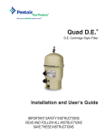
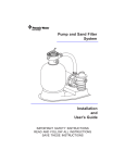
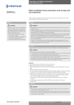
Logix Retrofit Kit - Performa Valve
11
1
10
17
16
6
8
4
9
5
2
3
7
12
13
14
16
15
Parts List
Item
Description
Item
1
Cover
10
2
Logix Control
11
3
Optic Sensor
12*
4
Camshaft
13*
5
Screw, Top Plate
14*
6
Spring
15*
7
Top Plate
16*
8
Rivet, Plastic Motor Assembly
17*
9
Motor Assembly
* Order separately, not included in retrofit kit, see Sizing Table 1 .
Description
Cable, Optic Sensor/Motor
Meter Cable, (760/762 only)
Injector
Cap, Injector
Refill Control, Flow Button Style
Refill Control, Ball/Cone Style
Ball
Backwash Control
Sizing Table 1: Performa Conditioner Configurations
Performa Cv 278 Conditioner
Configuration
Performa 268 Conditioner
Configuration
Tank Diameter
6
7
8
(inches)
E
F
G
Injector Type
Injector Color Yellow Peach Tan
Refill Control
Backwash
Control Type
.33
.33
.33
#6
#7
#8
* No ball required
**Externally mounted backwash control
9
10
12
13
14
14
16
18
L
M
N
H
J
K
L
L
Lt
Lt Blue Pink Orange Orange Orange Brown Green
Purple
.33
.33
1.30
.33
.33
.33
.33
.33
#9
#10
#12
#13*
#14*
EXT**
21
R
Dk
Gray
1.30
EXT** EXT** EXT**
Assembly Instructions
1. Place system into bypass and depressurize system by forcing the back flapper open.
2. Disconnect power to existing control.
3. Remove existing control, camshaft, top plate, refill flow control, and injector.
4. Install appropriate refill flow control and injector (see Table 1 for reference).
5. Install the Logix top plate onto the valve body.
6. Two sets of top plate screws are included in the kit. It is important that the replacement screws match the original
top plate screws. Use of improper screws will result in stripped valve body screw holes. To properly install the
screws:
• Place a screw into the hole. Rotate the screw backwards until the threads jump.
• Rotate the screw into the existing threads. It is important that new threads are not cut in the valve body.
• Tighten. Use the top plate screw tightening sequence to correctly install and tighten the screws (Figure 1).
7. Install the top plate spring (Figure 2).
8. Insert the optical sensor (Figure 3).
9. Assemble the camshaft to the top plate. Ensure that the arrow molded on the camshaft cup is facing up
(Figure 4).
3
2
1
5
9
13
17
15
11
7
3
4
8
12
16
18
14
10
6
2
2
1
Figure 1
2
Figure 2
Arrow
Figure 3
1
Figure 4
Figure 5
10. Install the 12V drive motor.
11. Install the optical sensor cable to the back of the Logix control and connect the wiring to the drive motor.
12. (760 and 762 Demand Controls Only) Install the meter cable to the outlet of the valve body and connect the
meter cable to the back of the Logix control.
13. Route all cabling through both clips on the top plate (Figure 5).
14. Connect the AC adapter cable to the back of the Logix control.
15. Install the Logix control onto the top plate.
16. Plug the AC adapter into a 120V power source. The Logix control will display ERR 3 as it automatically cycles
to the home position.
17. The ERR 3 message will clear when the control reaches the home position. The Logix control can now be
programmed. See the Programming Section in the Owners Manual.
©2009 Pentair Residential Filtration, LLC
P/N 3002944 Rev C FE09