1
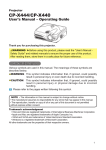
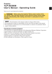
Projector
User's Manual - Operating Guide
TECHNICAL
In this section, the technical information about this projector is described.
WARNING Before using, read the "User's Manual - Safety Guide" and these
manuals to ensure correct usage through understanding. After reading, store
them in a safe place for future reference.
NOTE • The information in this manual is subject to change without notice.
• The manufacturer assumes no responsibility for any errors that may appear in this manual.
• The reproduction, transmission or use of this document or contents is not permitted without
express written authority.
RADEMARK ACKNOWLEDGEMENT :
• VGA and XGA are registered trademarks of the International Business Machines Corporation.
• Apple and Mac are registered trademarks of Apple Computer, Inc.
• VESA and SVGA are trademarks of the Video Electronics Standard Association.
• Windows is a registered trademark of Microsoft Corporation.
All other trademarks are the property of their respective owners.
1
TECHNICAL
Signal Connectors
VIDEO
L - AUD I O - R
2 10 4 5 6
7 8 9
AUDIO
S-VIDEO
1
RGB
3
CONTROL
Y
CB/PB
CR/PR
COMPONENT VIDEO
Port
Specification
1 RGB
Video signal: RGB separate, Analog, 0.7 Vp-p, 75 Ω terminator (positive)
H/V. sync. signal:TTL level (positive/negative)
Composite sync. signal: TTL level
D-sub 15-pin shrink jack
11 12 13 14 15
6
7
1
8
2
9 10
3
4
5
2 AUDIO
(interlocked 1 port)
5
8
4
7
3
6
2
1
No.
6
7
Signal
Ground Red
Ground Green
No.
11
12
3
Video input Blue
8
Ground Blue
13
4
5
Ground
9
10
Ground
-
14
15
Signal
SDA (DDC)
H. sync./Composite
sync.
Vertical sync
SCL (DDC)
No.
7
8
9
Signal
RTS
CTS
-
200 mVrms, 50 kΩ (max. 3.0 Vp-p), Stereo mini jack
AUDIO 5 L, 6 R
(interlocked
4 / 7 8 9 / 10 )
COMPONENT VIDEO
7 Y, 8 CB/PB,
9 CR/PR
200 mVrms, 50 kΩ (max. 3.0 Vp-p), RCA jack
Y signal: 1.0 Vp-p, 75 Ω terminator
CB/PB signal: 0.7 Vp-p, 75 Ω terminator
CR/PR signal: 0.7 Vp-p, 75 Ω terminator
3
No.
1
2
Signal
Ground
-
Mini Din 4-pin jack
10 S-VIDEO
2
No.
4
5
6
1.0 Vp-p, 75 Ω terminator, RCA jack
4 VIDEO
4
Signal
Video input Red
Video input Green
D-sub 9-pin plug
No.
Signal
1
2
RD
3
TD
3 CONTROL
9
No.
1
2
1
2
3
4
Signal
Color signal: 0.286 Vp-p (NTSC, burst), 75 Ω terminator
Color signal: 0.300 Vp-p (PAL/SECAM, burst), 75 Ω terminator
Brightness signal: 1.0 Vp-p, 75 Ω terminator
Ground
Ground
Example Of Computer Signal
Resolution
H×V
fH (kHz)
fV (Hz)
Rating
Signal mode
Display
mode
720 × 400
37.9
85.0
VESA
TEXT
Zoom in
640 × 480
31.5
59.9
VESA
640 × 480
35.0
66.7
640 × 480
37.9
72.8
640 × 480
37.5
75.0
640 × 480
43.3
800 × 600
800 × 600
VGA (60Hz)
Zoom in
Mac13"mode
Zoom in
VESA
VGA (72Hz)
Zoom in
VESA
VGA (75Hz)
Zoom in
85.0
VESA
VGA (85Hz)
Zoom in
35.2
56.3
VESA
SVGA (56Hz)
37.9
60.3
VESA
SVGA (60Hz)
800 × 600
48.1
72.2
VESA
SVGA (72Hz)
800 × 600
46.9
75.0
VESA
SVGA (75Hz)
800 × 600
53.7
85.1
VESA
SVGA (85Hz)
832 × 624
49.7
74.5
Mac16"mode
Zoom out
1024 × 768
48.4
60.0
VESA
XGA (60Hz)
Zoom out
1024 × 768
56.5
70.1
VESA
XGA (70Hz)
Zoom out
1024 × 768
60.0
75.0
VESA
XGA (75Hz)
Zoom out
1024 × 768
68.7
85.0
VESA
XGA (85Hz)
Zoom out
1152 × 864
67.5
75.0
VESA
SXGA (75Hz)
Zoom out
1280 × 960
60.0
60.0
VESA
SXGA (60Hz)
Zoom out
1280 × 1024
64.0
60.0
VESA
SXGA (60Hz)
Zoom out
1280 × 1024
80.0
75.0
VESA
SXGA (75Hz)
Zoom out
1280 × 1024
91.2
85.0
VESA
SXGA (85Hz)
Zoom out
1600 × 1200
75.0
60.0
VESA
UXGA (60Hz)
Zoom out
NOTE • Some computers may have multiple display screen modes. Use of some of these
modes will not be possible with this projector.
• Be sure to check jack type, signal level, timing and resolution before connecting this projector to a
computer.
• Depending on the input signal, full-size display may not be possible in some cases. Refer to the
number of display pixels above.
• Although the projector can display signals with resolution up to UXGA (1,600 x 1,200), the signal will
be converted to the projector’s panel resolution before being displayed. The best display
performance will be achieved if the resolutions of the input signal and projector panel are identical.
• The image may not be displayed correctly when the input sync. signal is “Composite Sync.” or
“Sync. on G”.
• Automatically adjustment may not function correctly with some input signals.
• When the image resolution is changed on a computer, depending on an input, automatic adjust
function may take some time and may not be completed. In this case, you may not be able to see a
check box to select “Yes/No” for the new resolution on Windows. Then the resolution will go back to
the original. It might be recommended to use other CRT or TFT monitors to change the resolution.
3
Initial Set Signals
The following signals are used for the initial settings.
The signal timing of some computer models may be different. In such case, refer to
adjust the V.POSIT and H.POSIT of the menu.
Back porch b
Front porch d
Display interval c
Back porch b
Front porch d
Display interval c
DATA
DATA
HSYNC
VSYNC
Sync a
Computer /
Signal
4
Sync a
Horizontal signal timing (µs)
TEXT
a
2.0
b
3.0
c
20.3
d
1.0
Computer /
Signal
Vertical signal timimg (lines)
TEXT
a
3
b
42
c
400
d
1
VGA (60Hz)
3.8
1.9
25.4
0.6
VGA (60Hz)
2
33
480
10
Mac 13"mode
2.1
3.2
21.2
2.1
Mac 13"mode
3
39
480
3
VGA (72Hz)
1.3
3.8
20.3
1.0
VGA (72Hz)
3
28
480
9
VGA (75Hz)
2.0
3.8
20.3
0.5
VGA (75Hz)
3
16
480
1
VGA (85Hz)
1.6
2.2
17.8
1.6
VGA (85Hz)
3
25
480
1
SVGA (56Hz)
2.0
3.6
22.2
0.7
SVGA (56Hz)
2
22
600
1
SVGA (60Hz)
3.2
2.2
20.0
1.0
SVGA (60Hz)
4
23
600
1
SVGA (72Hz)
2.4
1.3
16.0
1.1
SVGA (72Hz)
6
23
600
37
SVGA (75Hz)
1.6
3.2
16.2
0.3
SVGA (75Hz)
3
21
600
1
SVGA (85Hz)
1.1
2.7
14.2
0.6
SVGA (85Hz)
3
27
600
1
Mac 16"mode
1.1
3.9
14.5
0.6
Mac 16"mode
3
39
624
1
XGA (60Hz)
2.1
2.5
15.8
0.4
XGA (60Hz)
6
29
768
3
XGA (70Hz)
1.8
1.9
13.7
0.3
XGA (70Hz)
6
29
768
3
XGA (75Hz)
1.2
2.2
13.0
0.2
XGA (75Hz)
3
28
768
1
XGA (85Hz)
1.0
2.2
10.8
0.5
XGA (85Hz)
3
36
768
1
1152×864 (75Hz)
1.2
2.4
10.7
0.6
1152×864 (75Hz)
3
32
864
1
1280×960 (60Hz)
1.0
2.9
11.9
0.9
1280×960 (60Hz)
3
36
960
1
1280×1024 (60Hz)
1.0
2.3
11.9
0.4
1280×1024 (60Hz)
3
38
1024
1
1280×1024 (75Hz)
1.1
1.8
9.5
0.2
1280×1024 (75Hz)
3
37
1024
2
1280×1024 (85Hz)
1.0
1.4
8.1
0.4
1280×1024 (85Hz)
3
44
1024
1
1600×1200 (60Hz)
1.2
1.9
9.9
0.4
1600×1200 (60Hz)
3
46
1200
1
RS-232C Communication
Connecting The Cable
(1) Turn off the projector and the computer power supplies.
(2) Connect the CONTROL port of the projector with a RS-232C port of the computer by a RS232C cable. Use the cable that fulfills the specification shown in the following figure.
(3) Turn on the computer power supply and after the computer has started up, turn on the
projector power supply.
Projector
RS-232C cross cable
CONTROL
port
1
1
2
3
4
5
6
7
8
9
RD 2
TD 3
4
9
5
8
4
7
3
6
2
6
⇔
1
1
7
2
8
3
GND 5
9
4
6
5
RTS 7
CTS 8
D-sub 9-pin
jack
D-sub 9-pin
plug
9
Computer
RS-232C port
CD
RD
TD
DTR
GND
DSR
RTS
DTS
RI
5
4
9
3
8
2
7
1
6
⇔
D-sub 9-pin
jack
1
2
6
3
7
4
8
5
9
D-sub 9-pin
plug
Communications Setting
19200bps, 8N1
1. Protocol
Consist of header (7 bytes) + command data (6 bytes).
2. Header
BE + EF + 03 + 06 + 00 + CRC_low + CRC_high
CRC_low : Lower byte of CRC flag for command data
CRC_high : Upper byte of CRC flag for command data
3 Command data
Command Data Chart
byte_0
byte_1
byte_2
Action
low
byte_3
Type
high
low
byte_4
byte_5
Setting code
high
low
high
Action (byte_0 - 1)
Action
Classification
Content
1
SET
Change setting to desired value.
2
GET
Read projector internal setup value.
4
INCREMENT
Increment setup value by 1.
5
DECREMENT
Decrement setup value by 1.
6
EXECUTE
Run a command.
5
RS-232C Communication (continued)
Requesting projector status (Get command)
(1) Send the request code Header + Command data (‘02H’+‘00H’+ type (2
bytes)+‘00H’+‘00H’) from the computer to the projector.
(2) The projector returns the response code ‘1DH’+ data (2 bytes) to the computer.
Changing the projector settings (Set command)
(1) Send the setting code Header + Command data (‘01H’+‘00H’+ type (2 bytes) +
setting code (2 bytes)) from the computer to the projector.
(2) The projector changes the setting based on the above setting code.
(3) The projector returns the response code ‘06H’ to the computer.
Using the projector default settings (Reset Command)
(1) The computer sends the default setting code Header + Command data (‘06H’+‘00H’+
type (2 bytes) +‘00H’+‘00H’) to the projector.
(2) The projector changes the specified setting to the default value.
(3) The projector returns the response code ‘06H’ to the computer.
Increasing the projector setting value (Increment command)
(1) The computer sends the increment code Header + Command data (‘04H’+‘00H’+
type (2 bytes) +‘00H’+‘00H’) to the projector.
(2) The projector in creases the setting value on the above setting code.
(3) The projector returns the response code ‘06H’ to the computer.
Decreasing the projector setting value (Decrement command)
(1) The computer sends the decrement code Header + Command data (‘05H’+‘00H’+
type (2 bytes) +‘00H’ + ‘00H’) to the projector.
(2) The projector decreases the setting value on the above setting code.
(3) The projector returns the response code ‘06H’ to the computer.
When the projector cannot understand the received command
When the projector cannot understand the received command, the error code ‘15H’ is
sent back to the computer.
Sometimes the projector cannot properly receive the command. In such a case, the
command is not executed and the error code ‘15H’ is sent back to the computer. If this
error code is returned, send the same command again.
When the projector cannot execute the received command.
When the projector cannot execute the received command, the error code ‘1cH’ +
‘xxxxH’ is sent back to the computer. When the data length is greater than indicated by
the data length code, the projector ignore the excess data code.
Conversely when the data length is shorter than indicated by the data length code, an
error code will be returned to the computer.
NOTE • Operation cannot be guaranteed when the projector receives an
undefined command or data.
• Provide an interval of at least 40ms between the response code and any other code.
• The projector outputs test data when the power supply is switched ON, and when the
lamp is lit. Ignore this data.
• Commands are not accepted during warm-up.
6
RS-232C Communication (continued)
Command Data Chart
Names
Operation type
Command data
Header
Type
Setting code
Get
BE EF
03
06 00
B9 D3
02 00
07 20
00 00
Keystone
Increment
Decrement
BE EF
BE EF
03
03
06 00
06 00
DF D3
0E D2
04 00
05 00
07 20
07 20
00 00
00 00
Keystone Reset
Execute
BE EF
03
06 00
08 D0
06 00
0C 70
00 00
Get
BE EF
03
06 00
89 D2
02 00
03 20
00 00
Increment
BE EF
03
06 00
EF D2
04 00
03 20
00 00
Decrement
BE EF
03
06 00
3E D3
05 00
03 20
00 00
Execute
BE EF
03
06 00
58 D3
06 00
00 70
00 00
Get
BE EF
03
06 00
FD D3
02 00
04 20
00 00
Increment
BE EF
03
06 00
9B D3
04 00
04 20
00 00
Decrement
BE EF
03
06 00
4A D2
05 00
04 20
00 00
Execute
BE EF
03
06 00
A4 D2
06 00
01 70
00 00
4:3
BE EF
03
06 00
9E D0
01 00
08 20
00 00
16:9
BE EF
03
06 00
0E D1
01 00
08 20
01 00
15:9
BE EF
03
06 00
6E D0
01 00
08 20
03 00
32:15
BE EF
03
06 00
5E D2
01 00
08 20
04 00
WIDE
BE EF
03
06 00
CE D3
01 00
08 20
05 00
ZOOM
BE EF
03
06 00
3E D3
01 00
08 20
06 00
Get
BE EF
03
06 00
AD D0
02 00
08 20
00 00
NORMAL
BE EF
03
06 00
3B 23
01 00
00 33
00 00
WHISPER
BE EF
03
06 00
AB 22
01 00
00 33
01 00
BE EF
03
06 00
08 23
02 00
00 33
00 00
Normal
BE EF
03
06 00
C7 D2
01 00
01 30
00 00
H Inverse
BE EF
03
06 00
57 D3
01 00
01 30
01 00
V lnverse
BE EF
03
06 00
A7 D3
01 00
01 30
02 00
H&V Inverse
BE EF
03
06 00
37 D2
01 00
01 30
03 00
BE EF
03
06 00
F4 D2
02 00
01 30
00 00
Brightness
Brightness Reset
Contrast
Contrast Reset
Aspect
Whisper
Set
Set
Get
Set
Mirror
Get
CRC
Action
7
RS-232C Communication (continued)
Command Data Chart (continued)
Names
Language
Operation type
Set
Type
Setting code
English
BE EF
03
06 00
F7 D3
01 00
05 30
00 00
FRANÇAIS
BE EF
03
06 00
67 D2
01 00
05 30
01 00
Deutsch
BE EF
03
06 00
97 D2
01 00
05 30
02 00
ESPAÑOL
BE EF
03
06 00
07 D3
01 00
05 30
03 00
Italiano
BE EF
03
06 00
37 D1
01 00
05 30
04 00
Norsk
BE EF
03
06 00
A7 D0
01 00
05 30
05 00
Nederlands
PORTUGUÊS
BE EF
03
06 00
57 D0
01 00
05 30
06 00
BE EF
03
06 00
C7 D1
01 00
05 30
07 00
日本語
BE EF
03
06 00
37 D4
01 00
05 30
08 00
中文
BE EF
03
06 00
A7 D5
01 00
05 30
09 00
BE EF
03
06 00
57 D5
01 00
05 30
0A 00
BE EF
03
06 00
C7 D4
01 00
05 30
0B 00
BE EF
03
06 00
F7 D6
01 00
05 30
0C 00
SVENSKA
Gamma
Set
Custom Gamma
Custom
Color Temp
Set
Set
Set
BE EF
03
06 00
67 D7
01 00
05 30
0D 00
BE EF
03
06 00
97 D7
01 00
05 30
0E 00
Get
BE EF
03
06 00
C4 D3
02 00
05 30
00 00
NORMAL
BE EF
03
06 00
C7 F0
01 00
A1 30
00 00
CINEMA
BE EF
03
06 00
57 F1
01 00
A1 30
01 00
DYNAMIC
BE EF
03
06 00
A7 F1
01 00
A1 30
02 00
CUSTOM
BE EF
03
06 00
07 FD
01 00
A1 30
10 00
Get
BE EF
03
06 00
F4 F0
02 00
A1 30
00 00
Get
BE EF
03
06 00
08 F1
02 00
A0 30
00 00
Increment
BE EF
03
06 00
6E F1
04 00
A0 30
00 00
Decrement
BE EF
03
06 00
BF F0
05 00
A0 30
00 00
USER
BE EF
03
06 00
3B F8
01 00
B0 30
10 00
HIGH
MIDDLE
BE EF
BE EF
03
03
06 00
06 00
0B F5
9B F4
01 00
01 00
B0 30
B0 30
03 00
02 00
LOW
BE EF
03
06 00
6B F4
01 00
B0 30
01 00
BE EF
03
06 00
C8 F5
02 00
B0 30
00 00
50
BE EF
03
06 00
57 F7
01 00
B1 30
05 00
60
BE EF
03
06 00
C7 F6
01 00
B1 30
04 00
70
80
90
100
BE EF
BE EF
BE EF
BE EF
03
03
03
03
06 00
06 00
06 00
06 00
F7 F4
67 F5
97 F5
07 F4
01 00
01 00
01 00
01 00
B1 30
B1 30
B1 30
B1 30
03 00
02 00
01 00
00 00
BE EF
03
06 00
34 F4
02 00
B1 30
00 00
50
BE EF
03
06 00
13 F7
01 00
B2 30
05 00
60
BE EF
03
06 00
83 F6
01 00
B2 30
04 00
70
BE EF
03
06 00
B3 F4
01 00
B2 30
03 00
80
BE EF
03
06 00
23 F5
01 00
B2 30
02 00
90
BE EF
03
06 00
D3 F5
01 00
B2 30
01 00
100
BE EF
03
06 00
43 F4
01 00
B2 30
00 00
BE EF
03
06 00
70 F4
02 00
B2 30
00 00
Get
8
Action
SUOMI
Get
Custom User G
CRC
POLSKI
Get
Custom User R
Command data
Header
RS-232C Communication (continued)
Command Data Chart (continued)
Names
Operation type
Command data
Header
Type
Setting code
50
BE EF
03
06 00
EF F6
01 00
B3 30
05 00
60
BE EF
03
06 00
7F F7
01 00
B3 30
04 00
70
BE EF
03
06 00
4F F5
01 00
B3 30
03 00
80
BE EF
03
06 00
DF F4
01 00
B3 30
02 00
90
BE EF
03
06 00
2F F4
01 00
B3 30
01 00
100
BE EF
03
06 00
BF F5
01 00
B3 30
00 00
Get
BE EF
03
06 00
8C F5
02 00
B3 30
00 00
Get
BE EF
03
06 00
01 D2
02 00
05 20
00 00
Increment
BE EF
03
06 00
67 D2
04 00
05 20
00 00
Decrement
BE EF
03
06 00
B6 D3
05 00
05 20
00 00
Execute
BE EF
03
06 00
94 D3
06 00
05 70
00 00
Get
BE EF
03
06 00
B5 D7
02 00
12 20
00 00
Increment
BE EF
03
06 00
D3 D7
04 00
12 20
00 00
Decrement
BE EF
03
06 00
02 D6
05 00
12 20
00 00
Color Balance G
Reset
Execute
BE EF
03
06 00
04 DB
06 00
29 70
00 00
Get
BE EF
03
06 00
45 D2
02 00
06 20
00 00
Color Balance B
Increment
BE EF
03
06 00
23 D2
04 00
06 20
00 00
Decrement
BE EF
03
06 00
F2 D3
05 00
06 20
00 00
Color Balance B
Reset
Execute
BE EF
03
06 00
D0 D3
06 00
06 70
00 00
Get
BE EF
03
06 00
F1 72
02 00
01 22
00 00
Sharpness
Increment
BE EF
03
06 00
97 72
04 00
01 22
00 00
Decrement
BE EF
03
06 00
46 73
05 00
01 22
00 00
Execute
BE EF
03
06 00
C4 D0
06 00
09 70
00 00
Get
BE EF
03
06 00
B5 72
02 00
02 22
00 00
Color
Increment
BE EF
03
06 00
D3 72
04 00
02 22
00 00
Color Reset
Decrement
Execute
BE EF
BE EF
03
03
06 00
06 00
02 73
80 D0
05 00
06 00
02 22
0A 70
00 00
00 00
Get
BE EF
03
06 00
49 73
02 00
03 22
00 00
Tint
Increment
BE EF
03
06 00
2F 73
04 00
03 22
00 00
Decrement
BE EF
03
06 00
FE 72
05 00
03 22
00 00
Execute
BE EF
03
06 00
7C D1
06 00
0B 70
00 00
1
2
3
4
1
2
3
BE EF
BE EF
BE EF
BE EF
03
03
03
03
06 00
06 00
06 00
06 00
0E D7
9E D6
6E D6
FE D7
01 00
01 00
01 00
01 00
14 20
14 20
14 20
14 20
00 00
00 01
02 00
03 00
BE EF
03
06 00
F2 D6
01 00
15 20
00 00
BE EF
03
06 00
62 D7
01 00
15 20
01 00
BE EF
03
06 00
92 D7
01 00
15 20
02 00
4
BE EF
03
06 00
02 D6
01 00
15 20
03 00
Custom User B
Set
Color Balance R
Color Balance R
Reset
Color Balance G
Sharpness Reset
Tint Reset
My Memory Load Set
My Memory Save Set
CRC
Action
9
RS-232C Communication (continued)
Command Data Chart (continued)
Names
Operation type
Get
V Position
Increment
Decrement
V Position Reset
Execute
Get
H Position
Increment
Decrement
H Position Reset
Execute
Get
H Phase
Increment
Decrement
Get
H Size
Increment
Decrement
H Size Reset
Execute
Get
Over Scan
Increment
Decrement
Over Scan Reset
Execute
AUTO
RGB
Set
SMPTE240
Color Space
REC709
REC601
Get
COMPONENT
Set
Component
SCART RGB
Get
AUTO
NTSC
PAL
SECAM
Set
Video Format
NTSC 4.43
M-PAL
Frame Lock
3D-YCS
Set
Set
CRC
Action
Type
Setting code
0D 83
6B 83
BA 82
E0 D2
F1 82
97 82
46 83
1C D3
49 83
2F 83
FE 82
B5 82
D3 82
02 83
68 D2
91 70
F7 70
26 71
EC D9
0E 72
9E 73
6E 73
FE 72
CE 70
3D 72
4A D7
DA D6
79 D7
9E 75
FE 71
6E 70
6E 75
5E 72
FE 74
02 00
04 00
05 00
06 00
02 00
04 00
05 00
06 00
02 00
04 00
05 00
02 00
04 00
05 00
06 00
02 00
04 00
05 00
06 00
01 00
01 00
01 00
01 00
01 00
02 00
01 00
01 00
02 00
01 00
01 00
01 00
01 00
01 00
01 00
00 21
00 21
00 21
02 70
01 21
01 21
01 21
03 70
03 21
03 21
03 21
02 21
02 21
02 21
04 70
09 22
09 22
09 22
27 70
04 22
04 22
04 22
04 22
04 22
04 22
17 20
17 20
17 20
00 22
00 22
00 22
00 22
00 22
00 22
00 00
00 00
00 00
00 00
00 00
00 00
00 00
00 00
00 00
00 00
00 00
00 00
00 00
00 00
00 00
00 00
00 00
00 00
00 00
00 00
01 00
02 00
03 00
04 00
00 00
00 00
01 00
00 00
0A 00
04 00
05 00
09 00
02 00
08 00
BE EF
BE EF
BE EF
BE EF
BE EF
BE EF
BE EF
BE EF
BE EF
BE EF
BE EF
BE EF
BE EF
BE EF
BE EF
BE EF
BE EF
BE EF
BE EF
BE EF
BE EF
BE EF
BE EF
BE EF
BE EF
BE EF
BE EF
BE EF
BE EF
BE EF
BE EF
BE EF
BE EF
BE EF
03
03
03
03
03
03
03
03
03
03
03
03
03
03
03
03
03
03
03
03
03
03
03
03
03
03
03
03
03
03
03
03
03
03
06 00
06 00
06 00
06 00
06 00
06 00
06 00
06 00
06 00
06 00
06 00
06 00
06 00
06 00
06 00
06 00
06 00
06 00
06 00
06 00
06 00
06 00
06 00
06 00
06 00
06 00
06 00
06 00
06 00
06 00
06 00
06 00
06 00
06 00
N-PAL
BE EF
03
06 00
0E 71
01 00
00 22
07 00
Get
TURN OFF
TURN ON
Get
TURN OFF
NORMAL
STILL IMAGE
BE EF
BE EF
BE EF
BE EF
BE EF
BE EF
BE EF
03
03
03
03
03
03
03
06 00
06 00
06 00
06 00
06 00
06 00
06 00
0D 73
CB D6
5B D7
F8 D6
E6 70
76 71
86 71
02 00
01 00
01 00
02 00
01 00
01 00
01 00
00 22
14 30
14 30
14 30
0A 22
0A 22
0A 22
00 00
00 00
01 00
00 00
00 00
01 00
02 00
BE EF
03
06 00
D5 70
02 00
0A 22
00 00
Get
10
Command data
Header
RS-232C Communication (continued)
Command Data Chart (continued)
Names
Video NR
Progressive
S2-Aspect
Operation type
Set
Set
Set
Auto Adjust
Auto off
Auto Search
Blank Color
Blank on/off
Startup
Set
Set
Set
Set
Menu Position V
LOW
MIDDLE
HIGH
Get
Turn off
TV
Film
Get
TURN OFF
TURN ON
Get
Execute
Get
Increment
Decrement
TURN OFF
TURN ON
Get
Blue
White
Black
Get
TURN OFF
TURN ON
Get
TURN ON
TURN OFF
Get
Get
Increment
Decrement
Command data
Header
CRC
Action
Type
Setting code
BE EF
BE EF
BE EF
BE EF
BE EF
BE EF
BE EF
BE EF
BE EF
BE EF
BE EF
BE EF
BE EF
BE EF
BE EF
BE EF
BE EF
BE EF
BE EF
BE EF
BE EF
BE EF
BE EF
BE EF
BE EF
BE EF
BE EF
BE EF
BE EF
BE EF
BE EF
03
03
03
03
03
03
03
03
03
03
03
03
03
03
03
03
03
03
03
03
03
03
03
03
03
03
03
03
03
03
03
06 00
06 00
06 00
06 00
06 00
06 00
06 00
06 00
06 00
06 00
06 00
06 00
06 00
06 00
06 00
06 00
06 00
06 00
06 00
06 00
06 00
06 00
06 00
06 00
06 00
06 00
06 00
06 00
06 00
06 00
06 00
26 72
D6 72
46 73
85 73
4A 72
DA 73
2A 73
79 72
1A 71
8A 70
29 71
91 D0
08 86
6E 86
BF 87
B6 D6
26 D7
85 D6
CB D3
6B D0
9B D0
08 D3
FB D8
6B D9
C8 D8
0B D2
9B D3
38 D2
40 D7
26 D7
F7 D6
01 00
01 00
01 00
02 00
01 00
01 00
01 00
02 00
01 00
01 00
01 00
06 00
02 00
04 00
05 00
01 00
01 00
02 00
01 00
01 00
01 00
02 00
01 00
01 00
02 00
01 00
01 00
02 00
02 00
04 00
05 00
06 22
06 22
06 22
06 22
07 22
07 22
07 22
07 22
0B 22
0B 22
0B 22
0A 20
10 31
10 31
10 31
16 20
16 20
16 20
00 30
00 30
00 30
00 30
20 30
20 30
20 30
04 30
04 30
04 30
16 30
16 30
16 30
01 00
02 00
03 00
00 00
00 00
01 00
02 00
00 00
00 00
01 00
00 00
00 00
00 00
00 00
00 00
00 00
01 00
00 00
03 00
05 00
06 00
00 00
00 00
01 00
00 00
00 00
01 00
00 00
00 00
00 00
00 00
Menu Position V
Reset
Execute
BE EF
03
06 00
A8 C7
06 00
44 70
00 00
Menu Position H
Get
Increment
Decrement
BE EF
BE EF
BE EF
03
03
03
06 00
06 00
06 00
04 D7
62 D7
B3 D6
02 00
04 00
05 00
15 30
15 30
15 30
00 00
00 00
00 00
Menu Position H
Reset
Execute
BE EF
03
06 00
DC C6
06 00
43 70
00 00
BE EF
BE EF
03
03
06 00
06 00
8F D6
1F D7
01 00
01 00
17 30
17 30
00 00
01 00
BE EF
03
06 00
BC D6
02 00
17 30
00 00
Message
Set
TURN OFF
TURN ON
Get
11
RS-232C Communication (continued)
Command Data Chart (continued)
Names
Operation type
Volume
MUTE
Screen type
Set
Set
Lamp Time
Lamp Time Reset
Filter Time
Filter Time Reset
Magnify
Freeze
Set
Set
Get
Increment
Decrement
TURN ON
TURN OFF
Get
4:3
16:9- Top
16:9- Center
16:9- Bottom
Get
Get
Execute
Get
Execute
Get
Increment
Decrement
Normal
Freeze
Get
TURN OFF
TURN ON
Command data
Header
BE EF
BE EF
BE EF
BE EF
BE EF
BE EF
BE EF
BE EF
BE EF
BE EF
BE EF
BE EF
BE EF
BE EF
BE EF
BE EF
BE EF
BE EF
BE EF
BE EF
BE EF
BE EF
BE EF
BE EF
03
03
03
03
03
03
03
03
03
03
03
03
03
03
03
03
03
03
03
03
03
03
03
03
06 00
06 00
06 00
06 00
06 00
06 00
06 00
06 00
06 00
06 00
06 00
06 00
06 00
06 00
06 00
06 00
06 00
06 00
06 00
06 00
06 00
06 00
06 00
06 00
CRC
Action
Type
Setting code
31 D3
57 D3
86 D2
46 D3
D6 D2
75 D3
7A D6
EA D7
1A D7
8A D6
49 D6
C2 FF
58 DC
C2 F0
98 C6
7C D2
1A D2
CB D3
83 D2
13 D3
B0 D2
2A D3
BA D2
19 D3
02 00
04 00
05 00
01 00
01 00
02 00
01 00
01 00
01 00
01 00
02 00
02 00
06 00
02 00
06 00
02 00
04 00
05 00
01 00
01 00
02 00
01 00
01 00
02 00
01 20
01 20
01 20
02 20
02 20
02 20
01 00
13 20
01 00
13 20
01 00
90 10
30 70
A0 10
40 70
07 30
07 30
07 30
02 30
02 30
02 30
00 60
00 60
00 60
00 00
00 00
00 00
00 00
01 00
00 00
00 00
01 00
02 00
03 00
00 00
00 00
00 00
00 00
00 00
00 00
00 00
00 00
00 00
01 00
00 00
00 00
01 00
00 00
00 20
00 20
00 20
00 20
00 20
20 60
00 00
01 00
02 00
05 00
00 00
00 00
Power
Get
Input Source
Error Status
12
Set
RGB
Video
S-Video
Component
Get
Get
(Example Return)
00 00
(Off)
BE EF
BE EF
BE EF
BE EF
BE EF
BE EF
03
03
03
03
03
03
01 00
(On)
06 00
06 00
06 00
06 00
06 00
06 00
02 00
(Cool down)
FE D2
6E D3
9E D3
AE D1
CD D2
D9 D8
01 00
01 00
01 00
01 00
02 00
02 00
(Example of Return)
00 00
01 00
02 00
03 00
(Normal) (Cover-error) (Fan-error) (Lamp-error)
04 00
05 00
06 00
07 00
08 00
(Temp-error) (Air flow(Lamp- (Cool-error) (Filter-Error)
error)
Time-over)
09 00
(FilterMissing)