1
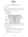
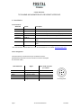
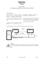
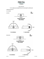
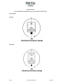
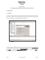
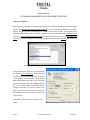
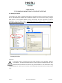
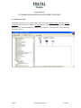
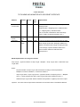
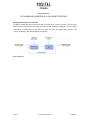
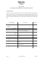
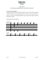
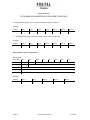
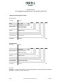
USER MANUAL TILTIX MEMS INCLINOMETER WITH DEVICENET INTERFACE AMERICAS FRABA Inc. 1800 East State Street, Suite 148 Hamilton, NJ 08609-2020, USA T +1 609 750-8705, F +1 609 750-8703 www.posital.com, [email protected] EUROPE POSITAL GmbH Carlswerkstrasse 13c 51063 Cologne, GERMANY T +49 221 96213-0, F +49 221 96213-20 www.posital.com, [email protected] ASIA FRABA Pte. Ltd. 20 Kallang Avenue Singapore 339411, SINGAPORE T +65 6514 8880, F +65 6271 1792 www.posital.com, [email protected] USER MANUAL TILTIX MEMS INCLINOMETER WITH DEVICENET INTERFACE TABLE OF CONTENTS GENERAL SAFETY ADVISE .................................... 3 ABOUT THIS MANUAL ......................................... 3 1. INTRODUCTION ............................................... 4 1.1 TILTIX INCLINOMETER .................................... 4 1.2 BENEFITS OF TILTIX: ..................................... 4 2 DEVICENET BASICS ........................................... 5 2.1 PHYSICAL LAYER ............................................ 5 2.2 DATA LINK LAYER ........................................... 6 3. INSTALLATION ................................................. 7 3.1 ACCESSORIES ................................................ 7 3.2 PIN ASSIGNMENT ............................................ 7 3.3 INSTALLATION PRECAUTIONS ........................... 8 3.4 MOUNTING INSTRUCTIONS ............................... 8 3.5 BUS TERMINATION .......................................... 9 3.6 MEASUREMENT AXES.................................... 10 4. RSNETWORX TM .............................................. 12 4.1. EDS W IZARD .............................................. 12 4.2 DRIVER CONFIGURATION ............................... 14 4.3. BUILDING THE NETWORK .............................. 15 4. 4 NETWORK CONNECTION ............................... 16 4.5 PARAMETER CONFIGURATION ........................ 17 4.6 CONFIGURATION OF A MASTER DEVICE ........... 21 5. DATA TRANSMISSION ................................... 23 5.1. THE OBJECT DICTIONARY ............................. 23 5.2 CAN-ID AND TYPES ...................................... 29 6. DETAILS OF OPERATING MODES ................... 30 6.1 POLLED MODE ............................................. 30 6.2 CHANGE OF STATE (COS) MODE................... 32 7. MODELS/ORDERING DESCRIPTION ................ 34 NOTES ............. ERROR! BOOKMARK NOT DEFINED. Page 2 TILTIX DeviceNet Manual 20110928 USER MANUAL TILTIX MEMS INCLINOMETER WITH DEVICENET INTERFACE G en e ra l S af et y Adv is e Ab out T his M anu al Important Information Background Read these instructions carefully, and have a look This user manual explains how to install and at the equipment to become familiar with the device configure the TILTIX inclinometer with a DeviceNet before trying to install, operate, or maintain it. interface with illustrations from a Rockwell PLC. The following special messages may appear Relate Note throughout this documentation & on the equipment, Version date: 20110928 to warn of potential hazards or to call attention Document Name: towards Manual_TILTIX_DeviceNet_NewLines.pdf information that clarifies/simplifies a procedure. The addition of this symbol to a Danger or Warning safety label, Imprint FRABA Inc. indicates that an electrical hazard exists, which will result in personal 1800 East State Street, Suite 148, Hamilton, injury if the instructions are not T +1 609 750 8705; F +1 609 750 8703 NJ 08609-2020, USA followed. Copyright This is the safety alert symbol. It is used for alerting, in case of potential personal injury or hazards. Obey all safety messages that follow this symbol to avoid possible injury or death. DeviceNet TM and TM ODVA are registered community trademarks of ODVA. © FRABA N.V., all rights reserved - Claims copyright on this documentation. It is not allowed to modify, extend, or hand over to a third party and to copy this documentation without written approval by Please Note FRABA Inc. Nor is any liability assumed for Electrical equipment should be serviced only by damages resulting from the use of the information qualified personnel. No responsibility is assumed by contained herein. Further, this publication and POSITAL for any consequences arising out of the features described herein are subject to change use of this material. This document is not intended without notice. as an instruction manual for untrained persons. User Annotation All readers are highly welcome to send us feedback and comments about this document. You can reach us by e-mail at [email protected] Page 3 TILTIX DeviceNet Manual 20110928 USER MANUAL TILTIX MEMS INCLINOMETER WITH DEVICENET INTERFACE 1. Int ro du ct io n This manual explains how to install and configure different grades and lower grades have entered the mass TILTIX gravity referenced inclinometers (suitable for industrial, military and heavy duty markets like mobile phones or tablet computers. applications) with a DeviceNet interface. The TILTIX series of inclinometers are available in 1.1 TILTIX Inclinometer two types. First, a single axis measurement type with a range of 0-360° (either clockwise or anti- TILTIX inclinometers sense and measure the angle clockwise) and the other type, a dual axis of tilt (Inclination/Slope/Elevation) of an object with measurement capable TILTIX model with a range of respect to the force of gravity. The angle is ±80°. measured with the relative change in electrical capacitance. In addition to high resolution, accuracy and protection class of IP69K, it has in-built active The basic principle behind this TILTIX inclinometer linearization and temperature compensation. This is a Micro-Electro-Mechanical Systems (MEMS) makes TILTIX suitable for rugged environments and sensor cell that is embedded to a fully molded versatile applications in industrial, heavy duty and ASIC. A simplified version of the sensor consists of military applications. two electrodes, one is fixed, and the other is flexible (connected with spring elements). When the Absolute inclinometers identify all the points of a inclinometer of movement by means of an unambiguous signal. measurement, a corresponding capacitance is Due to their capacity to give clear and exact values measured. If the sensor is tilted, the flexible to all inclinations positions, inclinometers have electrode will change its position relative to the fixed become one of the interesting alternatives to electrode. singleturn absolute encoders and a link between is This parallel to the results in a surface change of the capacitance between the two electrodes which is the mechanical and control systems. measured by the sensor cell. The change of the capacitance is converted to a corresponding inclination value. 1.2 Benefits of TILTIX: Small Size and Cost Efficient High Protection Class The MEMS sensor cell in TILTIX consists of a High Accuracy micromechanical Very Robust structure with an array of electrodes for better accuracy. Under the influence of gravity, the distance between some electrodes change and this distance can be detected by measuring the capacitance between the electrodes, as explained above. This technology is available in Page 4 TILTIX DeviceNet Manual 20110928 USER MANUAL TILTIX MEMS INCLINOMETER WITH DEVICENET INTERFACE 2 Dev ic eN et B a si cs DeviceNet is a digital, multi-drop network that connects and serves as a communication network between industrial controllers and I/O devices. Each device and/or controller is a node on the network. The DeviceNet specification defines the Application Layer and the Physical Layer. Below you can see the Basic DeviceNet Features and Functionality Network Size Up to 64 nodes Network Length Selectable end-to-end network distance varies with speed 125 Kbps 500 m (1,640 ft) 250 Kbps 250 m (820 ft) 500 Kbps 100 m (328 ft) Data Packets 0-8 bytes Bus Topology Linear (trunk line/drop line); power and signal on the same network cable Peer-to-Peer with Multi-Cast (one-to-many); Multi-Master and Master/Slave Bus Addressing special case; polled or change-of-state (exception-based) 2.1 Physical Layer DeviceNet uses a trunk-line/drop-line topology that provides separate twisted pair busses for both signal and power distribution. The possible variants of this topology are shown in the figure. Thick or thin cable can be used for either trunk lines or drop lines. End-to-end network length varies with data rate and cable thickness. Page 5 TILTIX DeviceNet Manual 20110928 USER MANUAL TILTIX MEMS INCLINOMETER WITH DEVICENET INTERFACE 2.2 Data Link Layer The Data Link layer is based on the CAN-specification. For the optimal industrial control will be defined two different messaging types. I/O messaging (Implicit Messaging) and explicit messaging. With Implicit Messaging becoming I/O data exchanged in real-time and with Explicit Messaging becoming data exchanged to configure a device. CIP (Common Industrial Protocol) make for the user available four essential functions: Unique control service Unique communication service Unique allocation of messaging Common knowledge base DeviceNet describes all data and functions of a device considering as object model. By means of that object-oriented description a device can be defined complete with single objects. An object is defined across the centralization by associated attributes (e.g. process data), his functions (read- or write access of a single attribute) as well as by the defined behavior. DeviceNet distinction is drawn between three different objects: Communication object Define the exchange messages over DeviceNet and becoming designated as Connection Objects. (DeviceNet Object, Message Router Object, Connection Object, Acknowledge Handler Object) System objects Define common DeviceNet-specific data and functions. (Identity Object, Parameter Object) Applications-specific objects Define device-specific data and functions. (Application Object, Assembly Object) Page 6 TILTIX DeviceNet Manual 20110928 USER MANUAL TILTIX MEMS INCLINOMETER WITH DEVICENET INTERFACE 3. In st al l at io n 3.1 Accessories Article No Article Description TILTIX360/080 Inclinometer TILTIX series of Inclinometers Download Datasheet* TILTIX Datasheet, specifications and drawings Download User Manual* Installation and Configuration User Manual (English) Download EDS-File* Electronic Datasheet (EDS) file for configuration 34050515 PAM 2m Female M12, 5pin A-coded connector, with 2m PUR shielded cable 10001978 PAM 5m 10005631 Terminal Resistor Female cable M12, 5pin A-coded connector, with 5m PUR shielded External terminal resistors for higher baud rate transmissions * The documentation and the EDS file can also be downloaded from our website http://www.posital.com/ 3.2 Pin Assignment The inclinometer is connected via a 5 pin round M12 connector. (Standard M12, Male side at sensor, Female at connector counterpart Or connection cable). DeviceNet Color Signal 5 pin round connector pin number Bare Drain 1 Red VS Supply Voltage 2 Black 0 V Supply Voltage 3 White CAN_H 4 Blue CAN_L 5 Page 7 TILTIX DeviceNet Manual Pin Assignment 20110928 USER MANUAL TILTIX MEMS INCLINOMETER WITH DEVICENET INTERFACE 3.3 Installation Precautions WARNING Do not remove or mount while the inclinometer is under power! Do not stand on the inclinometer! Avoid mechanical load! 3.4 Mounting Instructions TILTIX is a pre-calibrated device which can be put torque in the range of 1.5 – 2.5Nm for the screws. into immediate operation, upon simple and easy The M12 connectors are to be perfectly aligned and installation with a three point mount and setting of screwed till the end with a tightening torque in the preset. range of 0.4-0.6Nm. Its compact design and installation “anywhere” makes it versatile. Prior to installation, please check for all connection The TILTIX inclinometer can be mounted in any and mounting instructions to be complied with. number of fashions, depending on the situation. Please The mounting surface must be plane and free of regulations on low voltage technical devices. dust and grease. We recommend hex-head screws TILTIX Inclination sensors that are based on a with M4 or UNC bolts #6 (TILTIX Industrial) and M6 MEMS principle are optimal for fast measurements. also observe the general rules and or UNC bolts #12 (TILTIX Heavy-Duty) for the mounting. Use all the 3 screws for mounting but restrict the tightening Page 8 TILTIX DeviceNet Manual 20110928 USER MANUAL TILTIX MEMS INCLINOMETER WITH DEVICENET INTERFACE 3.5 Bus Termination If the inclinometer is connected at the end or electromagnetic beginning of the bus or for higher transmission single line structure minimizes reflection. baud rates compatibility requirements. A (≥125 KBaud) a terminating resistor of 121 Ohm 1%, 1/4W must be used in order to The TILTIX Inclinometer has internal terminating prevent the reflection of information back into the resistors that can be switched on or off by setting Bus. the right parameter or by explicit messaging See chapter 5.1 for additional information. The bus wires can be routed in parallel, twisted or shielded form in accordance with the The following diagram shows the components for the physical layer of a two-wire CAN-bus: TILTIX Inclinometer Other DeviceNet Nodes TILTIX Inclinometer PLC CAN High Wire 121Ω DeviceNet Master 121 Ω Can Low Wire WARNING The internal terminal resistors of the inclinometers are only functional when power is applied to the device. Care should be taken that this does not affect other devices on the DeviceNet network. Page 9 TILTIX DeviceNet Manual 20110928 USER MANUAL TILTIX MEMS INCLINOMETER WITH DEVICENET INTERFACE 3.6 Measurement Axes 3.6.1 TILTIX80 Industrial Heavy-Duty Page 10 TILTIX DeviceNet Manual 20110928 USER MANUAL TILTIX MEMS INCLINOMETER WITH DEVICENET INTERFACE 3.6.2 TILTIX360 Industrial Heavy Duty Page 11 TILTIX DeviceNet Manual 20110928 USER MANUAL TILTIX MEMS INCLINOMETER WITH DEVICENET INTERFACE 4. R S Net W or x TM 4.1. EDS Wizard The EDS File contains information about device specific parameters as well as possible operating modes of the inclinometer With this file you have a data sheet in an electronic format, which can be used to configure the device in the network, for example with RSNetWorx from Rockwell. 4.1 EDS Wizard To install the EDS file the EDS Wizard has to be started, that can be done in the menu Tools/EDS Wizard. If the EDS Wizard is activated successfully the Register an EDS File(s) has to be chosen and after that the button “Next” In the next step the Register a directory of EDS files has to be chosen and with Browse the path of the EDS file(s). That is indicated in picture 4.2. Page 12 TILTIX DeviceNet Manual 20110928 USER MANUAL TILTIX MEMS INCLINOMETER WITH DEVICENET INTERFACE 4.2 EDS Wizard The Wizard finds all EDS files that are located in the chosen path and operates a test to check the EDS files on errors. In the next step (see picture 4.3) pictures can be selected for the used nodes. With the button "Next" the installation can be finished. 4.3 Device Icon Selection Page 13 TILTIX DeviceNet Manual 20110928 USER MANUAL TILTIX MEMS INCLINOMETER WITH DEVICENET INTERFACE 4.2 Driver Configuration After a successful registration of the EDS file the next step is to choose the suitable driver for the DeviceNet interface. With Start/Programs/Rockwell Software/RSLinx in the menu the program RSLinx can be started. With this program the driver corresponding to the interface device can be chosen. For this example the RS232-DeviceNet interface device 1770-KFD is being used. In the next step the window Configure Drivers in the menu Communications/ Configure Drivers has to be started. In the drop down Menu Available Driver Types the driver type 1770-KFD has to be chosen and confirmed with the button Add New. (See picture 4.4) 4.4 Configure Drivers If the suitable driver is chosen it can be configured in the window Driver Configuration. For the KFD-1770 the Serial Port and the Data Rate has to be chosen. In this window it is also possible to set the desired Node Address (MAC ID) as well as one of the three possible Data Rates (125, 250, 500kBaud (picture 4.5). The 1770-KFD needs a "CAN acknowledge" to configure successfully. Any running device on the same bus with the same Baudrate can deliver this acknowledge. In the next step the driver can be given a custom name. Close RSLinx but make sure it is running in the taskbar. Page 14 4.5 Driver Configuration TILTIX DeviceNet Manual 20110928 USER MANUAL TILTIX MEMS INCLINOMETER WITH DEVICENET INTERFACE 4.3. Building the Network The network is built, simply by dragging and dropping the right devices actually connected on the physical bus from the Hardware list, available after an EDS file is installed. You would need to properly configure these devices, for the right Node Address, if they aren’t already set at the right value. The TILTIX Inclinometer can be found under Hardware/DeviceNet/Vendor/FRABA Posital GmbH/Generic Device/INCLINOMETER 080 degree, for this example. 4.6 Building the network WARNING If a Scanner module is connected to the bus it would most likely, but not necessarily, appear at node address 0. Sometimes DeviceNet Scanners are preconfigured to a different Baud rate. One should ensure that all devices on the bus are using the same Baud rate. If the network is not using 125KBd (default), then a point to point connection must be physically realized, otherwise the network would crash Page 15 TILTIX DeviceNet Manual 20110928 USER MANUAL TILTIX MEMS INCLINOMETER WITH DEVICENET INTERFACE 4. 4 Network Connection This chapter will explain how to switch a network online. In the menu Network/ Online the window Browse for network will be opened. If the driver for 1770-KFD has been chosen, this is explained in chapter 4.2, the network is online. After that RSNetWorx searches in the network for connecting nodes. That is also being showed in picture 4.7. 4.7 Browsing Network Page 16 TILTIX DeviceNet Manual 20110928 USER MANUAL TILTIX MEMS INCLINOMETER WITH DEVICENET INTERFACE 4.5 Parameter Configuration To configure the inclinometer the configuration window in the menu Device/Properties has to be opened, while the network is in online mode. . If parameters are changed while in offline mode, they can be saved temporarily by pressing Apply or OK. However, the new parameter values are not transferred to the device. To do so, go to online mode, double click on the device, go to the Parameters tab and press download. 4.5.1 General Tab In the General Tab one can see the Device Identity parameters. The Node Address can be changed. The device name can be changed or a Description can be added. Besides various vendor and device information can be seen Page 17 TILTIX DeviceNet Manual 20110928 USER MANUAL TILTIX MEMS INCLINOMETER WITH DEVICENET INTERFACE 4.5.2 Parameters Tab In the Parameters Tab you can click upload parameters to get the parameters from the device. Some of the TILTIX parameters are read only sensor values like the Slope long16 and Slope lateral16. These are scaled slope or inclination values. If a parameter is changed and downloaded to the device, the parameter is saved non-volatile. The parameters are also available in the class instance editor via explicit messaging IMPORTANT The easiest way to configure the device, without any side effects, is in the following order (the same as in the parameter tab) - Set the desired resolution (for both axes the same) - Set the operating parameter depending on: Inversion of the axis Enable scaling for the axis - When scaling is enabled, set the preset at the desired inclination and write it with preset enable parameter if required by application. - If scaling is enabled, set an additional differential offset if required The parameters are explained more in detail in Chapter 5.1.2. Page 18 TILTIX DeviceNet Manual 20110928 USER MANUAL TILTIX MEMS INCLINOMETER WITH DEVICENET INTERFACE 4.5.3 I/O Data Tab In the I/O Data Tab you see the different available assembly instances for the different connection types (. Each connection type offers the possibility of using three different assembly instances. In the I/O Data Tab the default assembly instances of the various connections are shown. The polled connection is activated by default if mapped to a master device. WARNING The assembly instances can be changed with the parameters Polled assembly instance and Cyclic/COS assembly instance. This is only necessary in RSNetWorx. Additional description of the modes can be found in the table below Polled Mode By an I/O -request telegram the connected master calls for the current process value. The inclinometer reads the current inclination value, calculates eventually set-parameters and sends back the obtained process value. (Default Configuration). Change-of-State Mode The inclinometer answers with current process value, if a change of inclination is detected. Important: If a high resolution is set, the device could send out messages very fast (<1ms) due to minor inclination changes leading to a high bus load. To prevent this, it is possible to set a Delta value, which limits the output to changes specified in the parameter COS Delta. Cyclic Mode The inclinometer transmits cyclically - without being requested by the master - the current process value. The cycle time can be programmed in milliseconds for values between 2 ms and 65535 ms. Page 19 TILTIX DeviceNet Manual 20110928 USER MANUAL TILTIX MEMS INCLINOMETER WITH DEVICENET INTERFACE 4.5.4 EDS File Tab In the EDS File Tab you can get some information of the EDS file, like when it was created and so on. You can open the EDS file by clicking on View File. Page 20 TILTIX DeviceNet Manual 20110928 USER MANUAL TILTIX MEMS INCLINOMETER WITH DEVICENET INTERFACE 4.6 Configuration of a Master device As an example the 1769 SDN scanner is taken. For most scanners the steps are identical. Double-click on the scanner and upload parameters from the device. Go to the tab Scan list. Select the inclinometer in the left window and add it to the scan list by clicking the upper arrow pointing to the right. Once the inclinometer has been added to the scan list, the I/O parameters can be edited. You can do this by clicking the Edit I/O Parameters button in the lower left corner. If Automap on Add is enabled, the default I/O connection of the inclinometer is activated once added to the scan list. Page 21 TILTIX DeviceNet Manual 20110928 USER MANUAL TILTIX MEMS INCLINOMETER WITH DEVICENET INTERFACE If Automap on Add is enabled, the Polled connection is activated by default. The input size (input means: input to the bus) is 4 Bytes, which corresponds to the Assembly instance 103 (Slope long16, Slope lateral16). If the Assembly instance is changed in the inclinometer to 101 (Slope long16) or 102 (Slope lateral16), the input size has to be changed here accordingly to 2 Bytes. VERY IMPORTANT If the Assembly instance and the input size are changed while a polled connection is established, this connection breaks down due to inconsistency and leads to a major fault. Make sure to close the polled connection before changing the Assembly instance. The inclinometer also supports the Change of State (COS) and the Cyclic connection. For both connections, the Assembly instance 103 (Slope long16, Slope lateral16) is default. If the Assembly instance is changed in the inclinometer to 101 (Slope long16) or 102 (Slope lateral16), the input size has to be changed accordingly to 2 Bytes. VERY IMPORTANT If the Assembly instance and the input size are changed while a Change of State or Cyclic connection is established, this connection breaks down due to inconsistency and leads to a major fault. Make sure to close the Change of State or Cyclic connection before changing the Assembly instance. Page 22 TILTIX DeviceNet Manual 20110928 USER MANUAL TILTIX MEMS INCLINOMETER WITH DEVICENET INTERFACE 5. D at a T r an sm is s ion The data transmission in the DeviceNet network is realized by message telegrams. Basically, these CAN-ID Message Header Message Body telegrams can be divided into the CAN-ID and 8 11 Bit 1 Byte 7 Byte following bytes as shown in the table 5.1. The Object Dictionary Instance and Attributes for all Objects. 5.1.1. Generic Objects/ Attributes Class ID: 3h (3d) Instance ID: 1h (1d) Attribute ID table: Attribute / Parameter MAC ID Attribute ID 1h Access GET/SET Data Type UINT (1d) Description The default setting for the MAC ID is 63d according to DeviceNet specification. Valid MAC IDs range from 0 to 63. The MAC ID can be changed to a different value, after being introduced on the bus so that other devices can pass the Duplicate MAC ID test on the same bus. Important: new MAC ID is adopted immediately after setting. Baud rate 2h GET/SET USINT (2d) The default setting for the Baud rate is 125 kBaud according to DeviceNet specification. Valid Baud rate settings are 125 kBaud, 250 kBaud and 500 kBaud. Important: new Baud rate is saved immediately after setting, but is adopted not until the device is powered off/on. BOI (Bus-off Interrupt) 3h (3d) GET/SET BOOL If set to FALSE and a CAN chip bus-off event is detected, the CAN chip is held in bus-off state and the device enters the Communication faulted state. If set to TRUE and a CAN chip bus-off event is detected, it may be possible to return the CAN chip to its normal operating mode and continue communicating. Page 23 TILTIX DeviceNet Manual 20110928 USER MANUAL TILTIX MEMS INCLINOMETER WITH DEVICENET INTERFACE Attribute / Attribute Access Data Description Parameter Bus-off ID 4h GET/SET Type USINT The Bus-Off Counter counts the number of times the counter (4d) CAN chip went to the bus-off state. The counter ranges from 0 to 255. The DeviceNet object resets the Bus-Off Counter to zero whenever it receives a Set_Attribute_Single request to the Bus-Off Counter attribute. The value of the Set_Attribute_Single has no meaning; just the request resets the counter. 5.1.1. Angle Objects/ Attributes Class ID: 65h (101d) Instance ID: 1h (1d) Attribute ID table: Attribute Attribute Access ID Number of 1h attributes (1d) Resolution 71h Data Implementation Type GET UINT The number of publicly implemented attributes GET/SET USINT The resolution parameter, based on the smallest unit of (113d) 0.001°, is used to program the desired number of steps per 1°. The values 10d, 100d and 1000d can be programmed, that correspond to a resolution of 0.01°, 0.1° and 1°. The default value is 10d or a resolution of 0.01° Important: if changed, all resolution dependent attributes’ values are switched and rounded to the new resolution automatically. Slope long16 72h GET INT (114d) Inclination in x-direction (longitudinal), shown as a digital number. The real world “degree” value can be calculated as follows Inclination in degrees =Slope long16 * Resolution E.g.: 16.34° Slope long16 73h operating (115d) parameter GET/SET USINT = 1634d * 0.01°(10d) This parameter controls scaling and inversion of the Slope long16 attribute. If Bit 0 is set, inversion of Slope long16 is enabled. If Bit 1 is set, Slope long16 offset and Differential slope long16 offset are added to Slope Page 23 TILTIX DeviceNet Manual 20110928 USER MANUAL TILTIX MEMS INCLINOMETER WITH DEVICENET INTERFACE Attribute Attribute Access ID Data Implementation Type long16. Both Bits can be set at the same time. Slope long16 74h preset value (116d) GET/SET INT This parameter defines a new, desired longitudinal slope value. Important: the Slope long16 offset is not calculated until it is triggered with the Slope long16 preset enable. Important: attribute shall be set in current resolution. Range: -80° - 80°. Slope long16 75h preset enable (117d) GET/SET USINT At the transition from 0 to 1 the Slope long16 preset enable triggers the calculation of Slope long16 offset according to the following: Slope long16 offset = Slope long16 preset value – current Slope long16 value. Slope long16 76h offset (118d) Differential 77h slope long16 (119d) GET INT The Slope long16 offset is calculated every time Slope long16 preset enable transitions from 0 to 1. GET/SET INT This attribute adds an additional, independent offset to Slope long16 if scaling of Slope long16 is enabled. offset Important: attribute shall be set in current resolution. Range: -80° - 80°. Diagnostic 78h slope long (120d) GET DINT The Diagnostic slope long allows access to the slope long value in the highest resolution (0.01°). This attribute can be used to get a slope value immediately based on the unit degree for diagnostic purposes. Important: this attribute is a 32-bit word. Slope 7Ah lateral16 (122d) GET INT Inclination in y-direction (lateral), shown as a digital number. The real world “degree” value can be calculated as follows Inclination in degrees =Slope lateral16 * Resolution E.g.: 16.34° Slope 7Bh lateral16 (123d) GET/SET USINT = 1634d * 0.01°(10d) This parameter controls scaling and inversion of the Slope lateral16 attribute. If Bit 0 is set, inversion of Slope operating lateral16 is enabled. If Bit 1 is set, Slope lateral16 offset parameter and Differential slope lateral16 offset are added to Slope lateral16. Both Bits can be set at the same time. Slope 7Ch lateral16 (124d) Page 24 GET/SET INT This parameter defines a new, desired lateral slope value. Important: the Slope lateral16 offset is not TILTIX DeviceNet Manual 20110928 USER MANUAL TILTIX MEMS INCLINOMETER WITH DEVICENET INTERFACE Attribute Attribute Access ID Data Implementation Type preset value calculated until it is triggered with the Slope lateral16 preset enable. Important: attribute shall be set in current resolution. Range: -80° - 80°. Slope 7Dh lateral16 (125d) GET/SET USINT At the transition from 0 to 1 the Slope lateral16 preset enable triggers the calculation of Slope lateral16 offset preset enable according to the following: Slope lateral16 offset = Slope lateral16 preset value – current Slope lateral16 value. Slope 7Eh lateral16 offset (126d) Differential 7Fh slope lateral16 (127d) GET INT The Slope lateral16 offset is calculated every time Slope lateral16 preset enable transitions from 0 to 1. GET/SET INT This attribute adds an additional, independent offset to Slope lateral16 if scaling of Slope lateral16 is enabled. offset Important: attribute shall be set in current resolution. Range: -80° - 80°. Diagnostic 80h slope lateral (128d) GET DINT The Diagnostic slope lateral allows access to the slope lateral value in the highest resolution (0.01°). This attribute can be used to get a slope value immediately based on the unit degree for diagnostic purposes. Important: this attribute is a 32-bit word. Polled 81h assembly (129d) instance GET/SET USINT With this attribute the input assembly instance for the Polling connection can be changed. There are three valid instances: - Instance ID 101: Slope long16 [Low byte],[High byte] - Instance ID 102: Slope lateral16 [Low byte],[High byte] - Instance ID 103: Slope long16, Slope lateral16 [Low byte Slope long16],[High byte Slope long16],[Low byte Slope lateral16],[High byte Slope lateral16] Important: The number of input bytes for the polling connection must be adjusted manually in the master device, if other instance than ID103 (default setting) is Page 25 TILTIX DeviceNet Manual 20110928 USER MANUAL TILTIX MEMS INCLINOMETER WITH DEVICENET INTERFACE Attribute Attribute Access ID Data Implementation Type used. Important: If there is an open connection between master and inclinometer, then a change in input bytes results in bus-off error, which is a major unrecoverable fault. The only possible solution to get the inclinometer back online again is a power cycle. Cyclic/COS 82h assembly (130d) GET/SET USINT With this attribute the input assembly instance for the Cyclic/COS connection can be changed. There are three instance valid instances: - Instance ID 101: Slope long16 [Low byte],[High byte] - Instance ID 102: Slope lateral16 [Low byte],[High byte] - Instance ID 103: Slope long16, Slope lateral16 [Low byte Slope long16],[High byte Slope long16],[Low byte Slope lateral16],[High byte Slope lateral16] Important: The number of input bytes for the cyclic/COS connection must be adjusted manually in the master device, if other instance than ID103 (default setting) is used. Important: If there is an open connection between master and inclinometer, then a change in input bytes results in bus-off error, which is a major unrecoverable fault. The only possible solution to get the inclinometer back online again is a power cycle. Size of moving 84h average filter (132d) GET/SET USINT This attribute controls the size of the moving average filter. If set to 0, the filter is deactivated. Valid values range from 0 to 250 (default value: 100). The values specify the number of entries in the filter array. In every program cycle, a new sensor value enters the array and the oldest value of the array is deleted. The filter output is the average over all array members. Weighting Page 26 85h GET/SET UINT This attribute controls the weighting factor of the TILTIX DeviceNet Manual 20110928 USER MANUAL TILTIX MEMS INCLINOMETER WITH DEVICENET INTERFACE Attribute Attribute Access ID factor Data Implementation Type (133d) recursive filter. A recursive filter is governed by the recursive filter following formula: NewSensorValue = Weighting factor * OldSensorValue + (1 – weighting factor) * NewSensorValue If set to 0, the filter is deactivated. Valid values range from 0 to 1000d corresponds internally to 0 to 1 Terminal 87h resistor (135d) COS Delta 88h GET/SET USINT Enables/ disables the terminating resistor if set to 1/0 GET/SET USINT A COS input message will be generated when the slope (136d) values changes by this value. Setting this attribute to 0 disables COS Delta and all changes in output generates a COS message. Important: attribute shall be set in current resolution. Maximum COS Delta value corresponds to 2°. NOTE: Implementation of scaling and inversion Slope long16 = physical inclination of slope long16 * Multiplier + Slope long16 offset + Differential slope long16 offset Where: - Physical inclination of Slope long16: axis and direction according to manual specification - Multiplier: if inversion is disabled: 1, if inversion is enabled: -1 - Slope long16 offset = Slope long16 preset – physical inclination of slope long16 at t acc * Multiplier, with tacc = preset acquisition time when Slope long16 preset enable transitions from 0 to 1 - Differential slope long16 offset: Adds an absolute value (positive or negative) to the sensor output. Important: This is also valid for Slope lateral16. Be aware of the min/max values of the different attributes. Page 27 TILTIX DeviceNet Manual 20110928 USER MANUAL TILTIX MEMS INCLINOMETER WITH DEVICENET INTERFACE NOTE: Implementation of the two filters The Moving average filter and the Recursive filter are configured in a series connection. The raw sensor values first run through the Recursive filter and secondly through the Moving average filter. All four possible combinations of active/inactive for both filters are valid. The filters are updated every program cycle (~700µs, depending on filter settings and I/O connections). Filter configuration Page 28 TILTIX DeviceNet Manual 20110928 USER MANUAL TILTIX MEMS INCLINOMETER WITH DEVICENET INTERFACE 5.2 CAN-ID and types DeviceNet is based on the standard CAN-protocol and uses an 11Bit (2048 specifiable messages) message identifier. For the identification of a device in a DeviceNet network 6Bits are enough because there are 64 nodes or MAC-ID’s in the network. The CAN-Identifier consists of the Message Group, Message ID and the MAC ID of the device. In the table below a user can see the important CAN-IDs for a certain communication type CAN- ID Bit Number 10 9 8 7 0 GROUP 1 6 5 4 3 Identity Usage 2 1 Hex Value 0 Source MAC ID GROUP 1 Message 000-3ff Message ID 0 1 1 0 1 Source MAC ID Slave’s I/O Change of State or Cyclic Message 0 1 1 1 1 Source MAC ID Slave’s I/O Poll Response or Change of State/Cyclic Acknowledge Message 1 0 MAC ID Group 2 GROUP 2 Messages 400 - 5ff Messag e ID 1 0 Destination MAC 0 1 0 ID Master’s Change of State or Cyclic Acknowledge Message 1 0 Source MAC ID 0 1 1 Slave’s Explicit/Unconnected Response Messages 1 0 Destination MAC 1 0 0 Master’s Explicit Request Message 1 0 1 Master’s I/O Poll Command/Change of State/Cyclic ID 1 0 Destination MAC ID 1 0 Destination MAC Message 1 1 0 ID 1 0 Destination MAC Group 2 Only Unconnected Explicit Request Message (reserved) 1 1 1 Duplicate MAC ID Check Messages ID Page 29 TILTIX DeviceNet Manual 20110928 USER MANUAL TILTIX MEMS INCLINOMETER WITH DEVICENET INTERFACE 6. D et ai ls of O p er at in g M odes This chapter consists of detailed structure of the telegrams needed for different operating modes, used along with proprietary DeviceNet Software for advanced users with detailed knowledge of CAN 6.1 Polled Mode For switching on the polled mode, the following telegrams are needed. In the following examples, a master with MAC ID or node address of 0A hex and a slave MAC ID of 03 hex is considered. Allocate Master / Slave Connection Set Allocate Polling Byte Offset Bit 7 Bit 6 Bit 5 Bit 4 0 Frag [0] XID MAC ID 1 R/R [0] Service [4B] Bit 3 Bit 2 Bit 1 Bit 0 Class ID [03] Instance ID [01] Allocation Choice [03] 0 0 Allocator MAC ID Definition CAN ID 10 9 8 7 6 5 4 3 2 1 0 Identity Usage 1 0 Destination MAC Hex Value 1 1 0 Group 2 Only Unconnected Explicit Request ID Message (reserved) Example: CAN-ID Byte 0 Byte 1 Byte 2 Byte 3 Byte 4 Byte 5 41E 0A 4B 03 01 03 0A 1. Setting the Expected_packet_rate of the Explicit Message Connection value to 0 Definition CAN-ID 10 9 8 7 6 5 4 3 2 1 0 Identity Usage 1 0 Destination MAC Hex Value 1 0 0 Master´s Explicit Request Message ID Page 30 TILTIX DeviceNet Manual 20110928 USER MANUAL TILTIX MEMS INCLINOMETER WITH DEVICENET INTERFACE Example: CAN-ID Byte 0 Byte 1 Byte 2 Byte 3 Byte 4 Byte 5 Byte 6 41C 0A 10 05 01 09 00 00 1. Setting the Expected_packet_rate of the Polling Connection value to 0 Example: CAN-ID Byte 0 Byte 1 Byte 2 Byte 3 Byte 4 Byte 5 Byte 6 41C 0A 10 05 02 09 00 00 Release Master / Slave Connection Set Release Polling Byte Offset Bit 7 Bit 6 Bit 5 Bit 4 0 Frag [0] XID MAC ID 1 R/R [0] Service [4C] Bit 3 Bit 2 Bit 1 Bit 0 Class ID [03] Instance ID [01] Release Choice [03] Example: CAN-ID Byte 0 Byte 1 Byte 2 Byte 3 Byte 4 41E 0A 4C 03 01 03 Page 31 TILTIX DeviceNet Manual 20110928 USER MANUAL TILTIX MEMS INCLINOMETER WITH DEVICENET INTERFACE 6.2 Change of State (COS) Mode The absolute inclinometer sends data, without any request from the host, when the actual process value is changing. No telegram will occur when the position value is not changing. . However, if a high resolution is chosen, minor changes in the inclination (vibrations and so on) can lead to a bus load of up to 100%. To prevent this, one can set the COS Delta parameter to limit the sensor output to changes in inclination specified in this parameter. Allocate Master / Slave Connection Set Allocate COS Byte Offset Bit 7 Bit 6 Bit 5 Bit 4 0 Frag [0] XID MAC ID 1 R/R [0] Service [4B] Bit 3 Bit 2 Bit 1 Bit 0 Class ID [03] Instance ID [01] Allocation Choice [51] 0 0 Allocator MAC ID Example: CAN-ID Byte 0 Byte 1 Byte 2 Byte 3 Byte 4 Byte 5 41E 0A 4B 03 01 51 0A Page 32 TILTIX DeviceNet Manual 20110928 USER MANUAL TILTIX MEMS INCLINOMETER WITH DEVICENET INTERFACE 2. Setting Expected_packet_rate of the Explicit Message Connection value to 0 Example: CAN-ID Byte 0 Byte 1 Byte 2 Byte 3 Byte 4 Byte 5 Byte 6 41C 0A 10 05 01 09 00 00 3. Setting Expected_packet_rate of the Change of State Connection value to 0 Example: CAN-ID Byte 0 Byte 1 Byte 2 Byte 3 Byte 4 Byte 5 Byte 6 41C 0A 10 05 04 09 00 00 Release Master / Slave Connection Set Release COS Byte Offset Bit 7 Bit 6 Bit 5 0 Frag [0] XID MAC ID 1 R/R [0] Service [4C] Bit 4 Bit 3 Bit 2 Bit 1 Bit 0 Class ID [03] Instance ID [01] Release Choice [51] Example: CAN-ID Byte 0 Byte 1 Byte 2 Byte 3 Byte 4 41E 0A 4C 03 01 51 Page 33 TILTIX DeviceNet Manual 20110928 USER MANUAL TILTIX MEMS INCLINOMETER WITH DEVICENET INTERFACE 7. M odel s/O rd e ri ng D es c ri pt io n TILTIX Industrial Description Type key TILTIX- XXX- X- XX XX- X Range 360° (1 axis) ± 80° (2 axis) Number of axis One for 360° Version Two for ± 80° Version Interface CANopen Version Software Version Mounting Vertical for 360° Version V Horizontal for ± 80° Version H Housing Material X XX 360 080 1 2 D1 00 Industrial (PBT) E Inclinometer Series TILTIX II Connection X- 2 PM Connector TILTIX Heavy-Duty Description Type key TILTIX- XXX- X- XX XX- X Range 360° (1 axis) ± 80° (2 axis) Number of axis One for 360° Version Two for ± 80° Version Interface CANopen Version Software Version Mounting Vertical for 360° Version V Horizontal for ± 80° Version H Housing Material X- XX 360 080 1 2 D1 00 Heavy-Duty (Aluminium) Inclinometer Series TILTIX II Connection X H 2 PM Connector Disclaimer © FRABA N.V., all rights reserved. We do not assume responsibility for technical inaccuracies or omissions. Specifications are subject to change without notice. Page 34 TILTIX DeviceNet Manual_Preliminary 20110928 USER MANUAL TILTIX MEMS INCLINOMETER WITH DEVICENET INTERFACE Document History st 1 Release – Anjan Nachiappa on September 28, 2011 Page 35 TILTIX DeviceNet Manual_Preliminary 20110928