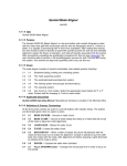
1
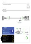
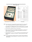
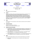
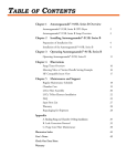
Marvell Nanolab
Member login
Lab Manual Index
Mercury Web
Berkeley Microlab
Tousimis 915B Critical-Point Dryer
(cpd)
1.0
T it le
Tousimis Model 915B Automegasamdri® CO2 critical-point drying system
Figure 1 - Tousimis 915B Critical Point Drying System
2.0
Pu rp ose
This document has specific information about the capabilities, configuration, and proper operation of the
Model 915B critical-point drying system.
cpd
3.0
4 .0
Chapter 2.14
Sc ope
3.1
The Automegasamdri-915B (cpd) is a fully automatic CO2 critical point drying apparatus (Figure
1). Its front panel consists of a pressure gauge, a temperature gauge, a purge timer knob, and six
process push buttons (COOL, FILL, PURGE, HEAT, BLEED, and VENT) with green LEDs. Only
COOL and FILL buttons need to be pushed for a complete process. The unit can also operate
under semi-automatic mode, but it is not recommended for the inexperienced users. The sample
holders for cpd are available for 2-inch through 6-inch wafers. Holders for the Tousimis 815
(cpd2) can also be used in cpd
3.2
On the flat panel of the unit, there are four micrometer valves that control the COOL, BLEED,
FILL and PURGE/VENT flows. They are set during the install, and should not need readjustment.
DO NOT ADJUST THE VALVES.
Ap p lic ab le Do cu me nts
Revision History
Automegasamdri-915B User Manual, Serial Number 1257, Tousimis Inc.
Tousimis 915B Operating Manual (24 MB PDF file)
Pressure vs. Temperature Graph for CPD Process
Verified Temperature Pressure Graph of Microlab CPD Process
5 .0
6.0
De f in it ions , Proc es s T er mino log y , No me nc latu re
5.1
CPD: critical-point drying (dryer)
5.2
LCO2: liquid carbon dioxide
Saf ety
6.1
The CPD system normally operates under very high chamber pressures. DO NOT DEVIATE
FROM THE CORRECT PROCEDURE FOR LOADING THE SAMPLE AND SECURING THE
CHAMBER LID – personal injury is quite possible otherwise.
6.2
An uncontrolled release of CO2 can cause personal injury due to frostbite. Again, DO NOT
DEVIATE from the correct procedures. Make very sure that persons near the system are always
wearing protective eyeware.
7.0
S t a t i st ic a l/ P r oce ss D a t a
8.0
A v a i lab l e P r oc ess es, P r oce ss N o t es
8.1
CPD uses copious amounts of LCO2. Requests for LCO2 cylinder changes are the primary CPD
problem report and result in decreased tool availability for all lab members. Review the
following Process Notes and attempt to minimize your LCO2 usage.
8.2
Extra long purge time does NOT increase the effectiveness of your critical point drying process;
it just wastes LCO2.
8.3
Minimize the amount of alcohol you add to the chamber. You only need enough alcohol to just
cover your parts.
8.4
Maximize the volume of the CPD chamber filled with Teflon® inserts. The more Teflon® in the
chamber, the less alcohol in the chamber, and the less LCO2 needed.
8.5
Most of the LCO2 is consumed during the PURGE process. Each number of the PURGE dial
indicator corresponds to 5 minutes of flowing LCO2; i.e., setting 1 = 5 min, Setting 2 = 10 min,
Setting 4 = 20 min, etc. The goal of the purge process is to replace essentially all the
methanol/IPA in the chamber with LCO2. Since methanol and IPA are especially soluble in
-2-
cpd
Chapter 2.14
LCO2, there is NOT a linear relationship between purge time and alcohol removal. Most alcohol
is removed from the chamber after only one LCO2 volume exchange. Once the alcohol has
been removed, the LCO2 can be heated to supercritical conditions and a phase change from
liquid to vapor can take place without crossing a liquid/vapor equilibrium line and generating the
surface tension forces that result in adhesion of released MEMS parts. (See Section 4,
Pressure vs. Temperature Graph for CPD Process).
8.6
Process staff has verified that there was no remaining alcohol and therefore a completely
effective CPD process was performed with the following samples and volumes of alcohol.
4” Wafer
Number of wafers
Amount of Methanol
Purge Setting
Cool CO2
Chamber CO2
4
120 ml
4
4.5 lb
10.5 lb
1
40 ml
2
5.0 lb
3.5 lb
6” Wafer
Number of wafers
Amount of Methanol
Purge Setting
Cool CO2
Chamber CO2
4
320 ml
6
5.5 lb
13.5 lb
1
80 ml
2
4.5 lb
7.5 lb
8.7
For a single 4” or 6” wafer there is never a need for a purge setting greater than 2.
8.8
CPD is often one of the last steps of a lengthy MEMS process. Users are wary to risk their parts
to an ineffective CPD process. If you would like to verify that a lower purge time is suitable for
your process – run a dummy process one time. Add a non-critical sample and just enough alcohol
to cover the sample. Use the recommended minimum purge time. Verify that the chamber is
absolutely dry (no residual alcohol) at the end of the process. If the chamber is dry, you have
performed a fully effective CPD process.
8.9
If you ever observe residual alcohol in the chamber using the minimum recommended times,
report it as a CPD problem on the wand.
Important Note: Any residual HF remaining on your samples from previous steps can easily damage
the High Pressure Sensor on the cpd tool. Therefore, extra care must be taken to
thoroughly rinse off your part(s) before entering the cpd chamber.
9.0
O pe rat ion
9.1
Preparation
9.1.1
Before starting to use cpd, the user should check the liquid CO2 cylinder weights. See
Figure 2. If either of the weights is 25 lbs (or more) below their full weights, report a fault
on the WAND. This will give the staff adequate time to change the tank(s). A full tank
provides 30 lbs of CO2 according to the vendor. Therefore, the cylinder has to be
changed before 30 lb has been used up.
-3-
cpd
Chapter 2.14
Figure 2 - CPD and CPD2 Cylinder Scale Readouts
9.2
9.1.2
Clean samples carefully. Photoresist residue may re-deposit on the dried samples or the
chamber walls.
9.1.3
Make sure your samples are sufficiently rinsed after a wet process that involves HF
and/or other acid treatments, before entering the cpd chamber.
9.1.4
The user should also decide on the purge time beforehand and set the purge timer knob
accordingly. A setting of 1 indicates 5 minutes; a setting of 2 indicates 10 minutes; and so
on, to a maximum of 45 minutes. See Section 8 for Process Notes regarding appropriate
Purge times.
Operation
9.2.1
Check for reservations on the WAND for cpd or cpd2. The two systems share one CO2
tank; therefore they cannot be used simultaneously. Likewise, if either of the systems is
enabled already, the ON indicator above the system (on the front of the hood) will be
illuminated.
9.2.2
Enable cpd on the WAND. Note the ON indicator at the front of the hood lights up (Figure
3). The green LED on the VENT button (on the cpd console) will go on. This means the
unit is in the vent mode.
Figure 3 - CPD Enable Indicator
9.2.3
Ensure that the three-way manual valve (Figure 4) on the front of the hood points toward
CPD. If not, rotate the handle 180° until it does.
Figure 4 - CO2 Selection Valve
-4-
cpd
Chapter 2.14
9.2.4
Verify that the cylinder valves of both liquid CO2 cylinders are open. Check the weights of
the cylinders. Both liquid CO2 cylinders are located behind the tools on the other side of
the 432B wall. One is labeled CHAMBER CO2 and the other, COOL CO2. Report a fault
on the WAND if the weight is 20 lbs or more below its full weight.
9.2.5
Record the weight of both CO2 cylinders (see 9.2.25 below).
9.2.6
Remove the eight steel nuts and eight bronze washers from the chamber lid. Place a
clean Techni-cloth or two on the table top. Using the index fingers of both hands, insert
your fingers into the loops on the lid and lift the lid from the chamber and place it onto the
Techni-cloths. The lid is heavy – do this slowly and carefully. Do not allow the lid bottom
to contact the top of the steel bolts – the bolts will scratch the lid sealing surface and
cause it to leak.
9.2.7
Remove the four Teflon® spacer rings from the chamber (Figure 5). Remember to wear
poly gloves (clear) when you are handling Teflon® spacer rings.
Figure 5 - Teflon® Spacer Rings (4)
9.2.8
Clean the chamber using methanol/IPA and dry with N2 gun. Repeat several times if
necessary. Do not use the handi-wipes from the 432B hood – they shed lint, and the lint
will end up all over your sample as well as the chamber. This has been experimentally
verified. Use only Techni-cloth cleanroom wipes. Refit the appropriate Teflon® spacer
rings back into the chamber:
Sample
9.2.9
Rings to Use
6” wafer
None
4” wafer
One (the largest)
3” wafer
Two largest
2” wafer
Three largest
Something smaller
All four
As you replace the rings into the chamber, wipe them down with a Techni-cloth and
IPA/methanol. Note that when all four rings are in the chamber, the available sample size
is the same as for cpd2.
9.2.10 Place only enough Methanol or IPA into the chamber to cover your sample(s). More
alcohol requires a longer purge time (see 9.1.3), and thus more CO2.
-5-
cpd
Chapter 2.14
9.2.11 Place your sample(s) in the chamber. There are five Teflon® sample holders available: 6”,
4”, 3”, 2”, and pieces-parts basket. The sample holders are stored in a drawer below the
cpd systems. Alternatively, some users have custom sample holders, and in fact the
system can be used without any sample holder at all, by placing the sample on the
bottom of the chamber. Sample holders from cpd2 can also be used.
Be careful to keep the surface of the sample wet while transferring it into the chamber.
Practice and experience are very helpful here.
9.2.12 Place the lid on the chamber. Take great care to avoid allowing the bottom of the lid to
make contact with the top of the steel studs. Once the bolt holes in the lid line up with the
studs, as viewed from directly above, carefully lower the lid into place.
9.2.13 Press the COOL button. The LED on the button will go on (VENT LED will go off). The
unit will go on cooling by itself until slightly below 0°C. If it takes more than 2 minutes to
reach 0°C, the COOL LCO2 cylinder may be depleted.
Note that we could easily have begun the cool down cycle before placing the lid on the
chamber. Why might this be a bad thing? If we were to cool down the chamber before
installing the lid, we run the risk of condensing moisture from the lab air. By cooling the
chamber after placing the lid in place, we minimize that risk. The cool down takes only a
couple of minutes anyway, so time savings is not an issue.
9.2.14 Replace the eight bronze flat washers, then replace the eight steel nuts, but do not
tighten past gentle contact.
9.2.15 Using the spanner wrench, and working in a star crossing pattern, begin tightening the
nuts one at a time. It is critically important to tighten the bolts evenly to avoid leakage
and damage to the lid or the chamber. See Figure 6. Make two passes around the lid in
the star pattern. Proper tightening does not require a lot of force – don’t try to kill it!
Figure 6 - Lid Tightening Sequence
9.2.16 Verify that the chamber temperature has reached 0° C, and then press the FILL button.
The unit will start filling the chamber with liquid CO2. The user can see a visible liquid flow
through the fill port. If not, the CHAMBER LCO2 cylinder may be depleted. Now the unit
is in the AUTOMATIC mode. It is not necessary to push any more buttons until the
process has completed.
9.2.17 After 8 minutes, the unit switches to PURGE Mode automatically. The PURGE LED will
be on. The Methanol/IPA is exchanged with liquid CO2. The PURGE time depends on the
-6-
cpd
Chapter 2.14
setting of the timer knob the user set before the process starts. See Section 8 for
important notes on PURGE time settings.
9.2.18 Upon Completion at the PURGE mode, the unit will advance into a POST-PURGE-FILL
mode in which the chamber fills with LCO2 for an additional 4 minutes. This will be
indicated by illumination of both the FILL and PURGE LEDs.
9.2.19 The unit will then switch to the HEAT mode. The HEAT LED will be on.
9.2.20 When the pressure reaches around 1350 psi and the temperature is above 31°C, the
Tousimis Equilibrium cycle starts. At this point the HEAT LED will be blinking for 4
minutes.
9.2.21 At the end of the Tousimis Equilibrium, the unit switches to BLEED cycle and the BLEED
LED will be on. The Bleed flow should be around 40-50 SCFH for pressures between
1,300 and 400 psi. This setting should yield an average of approximately 100-150 psi/min
reduction in pressure. The temperature should be above 31°C.
9.2.22 There may be a hissing or cracking sound in the BLEED cycle. It is normal because
gaseous CO2 or dry ice may be coming out the unit.
9.2.23 When the pressure drops below 300 psi, the unit switches to VENT mode. The VENT
LED will be on. Do not try to loosen the nuts until the chamber is completely vented - it
will damage the threads on the nuts and the chamber. After 3 to 4 minutes, the chamber
will come to atmospheric pressure. NOW the chamber lid may be removed by
alternatively and evenly loosening all of the steel nuts using the spanning wrench.
Remove the nuts, the bronze washers, the lid (carefully) and the (dry) sample.
9.2.24 Clean and blow dry the chamber and lid with methanol/IPA if you see any residue.
Replace ALL of the Teflon® spacer rings. Close the lid to keep the chamber clean and
moisture free. Replace the flat washers and the steel nuts, but do not tighten them.
9.2.25 Leave the cylinder valves of both liquid CO2 cylinders open. Report the initial and final
cylinder weights on the WAND comment when disabling cpd. If either of the final cylinder
weights is below 20 lb of the full weight, report a fault on the WAND also.
1 0 .0 T ro ub l es ho ot i ng G u id e l in es
10.1
A backing ring has been added to the chamber o-ring groove which is supposed to extend the
life of the Teflon o-ring greatly. The backing ring looks like a thin, somewhat flat o-ring with a
triangular cross-section. It is located under the normal o-ring and should not be removed
during o-ring changes. If it comes out with the o-ring, it should be re-installed just as it came
out. Care should be taken to ensure this as it can be installed upside down. A spare o-ring is in
the cpd drawer beneath the tool. More spares are available from the stockroom.
10.2
There should be no reason to adjust the Fill or Bleed needle valves. These valves have been
adjusted and set - so that there is slow flow through the chamber during the purge process - but
the LCO2 level stays constant - and the chamber remains almost completely full of LCO2.
The most convenient way to verify that these valves are properly set is to allow a minimum
head space in the chamber just below the viewing window. The minimum head space enables
viewing of just a few mm size bubbles through the chamber window. Track these bubbles by
eye during the purge process so that the flow through the chamber enables a 'bubble travel
speed of about 1inch/second.
Once the valves have been properly set, staff use the small allen set screws to lock the needle
valves in position. Though there is a chamber inlet and exit filter, these valves sometimes
become partially blocked and the needle valves need to be readjusted. If you need to readjust
the needle valves, be sure to loosen the allen set screws prior to attempting to turn the needle
valve. Otherwise you will strip the needle valve handle. Then follow the procedure above to set
the needle valves and re-tighten the needle valve set screws.
-7-
cpd
Chapter 2.14
10.3
If you enable cpd and find the vent LED not lit on, check the main power of cpd. It might be
OFF by accident.
1 1 .0 Q ua l if i cat io n Pr oce du re s
11.1 Potential new users should arrange ahead of time to have an existing user review cpd operation.
Casual questioning (e.g. Hey, can you review this with me for a moment?) is not to be
considered an official review period.
11.2 The first question that should be asked is whether Section 2.8, Tousimis Critical Point Dryer of
the WAND has been thoroughly reviewed? If not, insist that it be reviewed before the meeting.
11.3 The meeting between the current and new user should be scheduled for enough time to explain
equipment operation, load & unload sequence, etc. Equipment time can be recharged to new
user’s account if necessary.
11.4 Step 3 should be done at least twice by two different current users.
11.5 Superusers will first ask: Who trained you? of the new user. Training implies adequately
following Steps 11.1-11.4 above. The users identified as being the ones who did the training will
be responsible for the information conveyed by the new user during the qualification.
Teflon® is a registered trademark of DuPont.
-8-