1
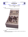
Marvell NanoLab
Member login
Lab Manual Contents
MercuryWeb
Berkeley Microlab
Chapter 3.5
APT Chrome Process
(aptchrome - 382A)
1.0
Titl e
APT Chrome Process
2.0
Pu rpo s e
The APT Chrome Mask Developer is an automated photomask processing unit for chrome and iron
oxide masks which have been exposed in the pattern generator. This unit is contained in a gated
exhaust enclosure with both red and yellow light fixtures in the hood.
3.0
S cop e
This chapter describes the chrome process used in the APT chrome unit on the left in 382A. All
programs to which we refer in this manual are listed in Section 9.3. The aptchrome mask developer
accommodates masks in the following sizes: 2.5”, 4”, 5”, 6” and 7”.
4. 0
Appl i ca bl e D o cum ent s
Revision History
5. 0
Def in it io ns a nd P ro c es s Te r min olo gy
6.0 S afet y
Before you proceed, please note the following: The door to the process chamber should be kept
closed and latched at all times except when loading or unloading masks.
7. 0
St ati st ic al / P roc e s s D at a
8. 0
Av ai l abl e P ro c es s , G as e s, Pr oc e ss N ote s
9.0 Equ ip men t O p e r at io n
9.1
Enable the aptchrome on Mercury.
The system power to the aptchrome can be turned on by flicking on the blue power on rocker
switch which is located on the left side of the aptchrome. The program status will then be displayed
on the program recipe display screen on the front panel. Processing programs 90 (develop), 91
(etch), 92 (strip resist), 93 (rinse and dry),and 99 (test lines) are each separately activated by a red
rocker switch that will illuminate when selected. The STOP/RESET is a square red button and the
recipe START a square black button. In addition there is white rocker switch for manual override;
this is located next to the red Prog.99 switch. This feature is most useful when you want to slightly
overetch a plate. To utilize this feature, start the etch recipe then engage the override switch
before the etchant stops dispensing. The display screen will show MANUAL then how many
seconds the etchant is dispensing. When the desired overetch time has been realized, turn the
override switch off and the recipe will continue on to the next steps until the program is completed.
Follow the same steps for overdevelop.
To operate the tool, the program recipe display screen will prompt you to SELECT A
PROGRAM AND PRESS START. Select a recipe by pressing the desired recipe rocker switch
aptchrome
Chapter 3.5
which will illuminate when selected. Next, press the START button. Once a recipe has been
started, it will continue until it finishes and the program recipe display screen will read END OF
PROGRAM. While the recipe is running, the display on the screen will show how much time has
elapsed since the start of the recipe.
If the red STOP/RESET button is pressed, the tool will immediately cancel the remainder of
the recipe and stop whatever it is doing. The program recipe display screen show you that the
recipe has been stopped and will ask you to reset the system by pressing the STOP/RESET button
once more. The display will once again prompt you to select a recipe and press START.
Only one recipe may be run at a time; if more than one is selected and the START button is
pressed, neither recipe will run; the system will wait for you to deselect one of the programs.
Important Note: The STOP/RESET button does exactly that: it stops the recipe at once and does
Not automatically skip to the next step!
9.2
Checking Chemical Lines
Before starting your process, you will run a test program (Program 99- test lines) to check that
each chemical is flowing properly at each step. The chemical(s) should dispense from the
nozzle(s) as a fan-shaped spray. If the spray comes out in a thin stream, it means the nozzle is
clogged and needs to be replaced before any processing on a plate is attempted. Report this
problem promptly on FAULTS. The program is set up to allow each required chemical to spray in
sequence, with water rinses in between. Program 99 is described in Section 9.3 below.
9.2.1
Select program number 99 – test lines. The lamp is on at all times during Program 99.
9.2.2
Press START button.
9.2.3
When the program starts, make sure that the desired chemical starts to spray out of its
respective nozzle (30 seconds.)
9.2.4
Let the water rinse cycle run through (30 seconds). The next chemical should then begin
to spray.
Continue in this fashion until you have worked your way through all the
programs.
If too much water beads up on the door and prevents you from being able to see through,
briefly open the door and wipe it dry with a techni-cloth. Techni-cloths are kept in a
dispenser on the deck of msink10.
9.2.5
9.3
If everything checks out, proceed to Section 9.3. If there is a problem, contact the process
staff for help and report the problem on the Wand using the FAULTS program.
Processing Masks
9.3.1
Run the develop Program 90 without a plate initially to make sure the lines are clear.
9.3.2
Load mask, chrome side up, onto the spinner, seating all 4 corners securely so that it does
not fly off and break during the spin.
9.3.3
Close and latch the door and select the desired program number.
9.3.4
Press START.
9.3.4.1 Develop: Program 90
Program 90, which is the initial develop step, does not turn on the lamp during the
entire process so that the plates are not exposed. After a standard develop step
the plate should be inspected for complete development at the Leitz microscope in
382A, next to the pattern generator.
9.3.4.2 Etch: Program 91
-2-
aptchrome
Chapter 3.5
Beginning with the etch step, the lamp will be turned on for all steps. The
aptchrome endpoint detectors automatically determine the completion of the metal
etching process. After this step it is recommended to inspect the plate at the Leitz
microscope.
9.3.4.3 Photoresist Strip: Program 92
The remaining photoresist is exposed with the lamp in the first step and then
removed with developer concentrate. Program 92 is a strip only process, which
removes the photoresist from the mask following the develop and etch steps.
9.3.5
When the process is finished, check to see if the plate is completely dry on both sides. If
not, use the N2 anti-static gun mounted at the pattern generator chamber to blow it dry.
9.3.6
Run Program 93 to water rinse the aptchrome chamber.
9.3.7
When Program 93 is finished, unlatch the door and use the DI water deck gun at msink10
to rinse the interior of the chamber.
9.3.8
Use a techni-cloth wetted with Nova Clean spray to wipe and clean the interior of the
latched window; techni-cloths can be found in a dispenser which is on the msink10 deck;
the Nova Clean spray can be found on the deck of the aptchrome.
9.3.9
Disable the aptchrome on the Mercury.
Clean up the sink and any chemical spills on the APT surfaces as well.
9.4
Programs
The programs stored in the APT Chrome Developing system are listed below.
Program 99 – Chrome Process Test
Spin Speed
Step
Chemical
Output
Description
(103
RPM)
Time
(sec.)
1
Shipley Microposit Developer 452
Lamp
on
Developer Nozzle
.00
30
2
Water Rinse
Lamp
on
Top/Bottom Rinse
.00
30
3
Concentrated Chromium Etchant CR-7
Lamp
on
Etchant Nozzle
.00
30
4
Water Rinse
Lamp
on
Top/Bottom Rinse
.00
30
5
Shipley Microposit Developer 452
Lamp
on
Stripper Nozzle
.00
30
6
Water Rinse
Lamp
on
Top/Bottom Rinse
.00
30
-3-
aptchrome
Chapter 3.5
Program 90 – Develop Only
Step
Chemical
Output
Description
(103 RPM)
Time
(sec.)
Spin Speed
1
Water Rinse
Lamp
off
Top/Bottom Rinse
.22
10
2
Shipley Microposit Developer 351
(5:1)
Lamp
off
Developer Nozzle
.22
50
3
Water Rinse
Lamp
off
Top/Bottom Rinse
.22
60
4
Spin Dry
Lamp
off
(Spindry)
.95
120
Spin Speed
(103 RPM)
Time
(sec.)
Program 91 – Etch Only
Step
Chemical
Output
Description
1
Water Rinse
Lamp on
Top/Bottom Rinse
.22
10
2
Concentrated Chromium Etchant CR-7
Lamp on
Etchant Nozzle
.22
100
3
Water Rinse
Lamp on
Top/Bottom Rinse
.22
60
4
Spin Dry
Lamp on
(Spindry)
.95
120
Spin Speed
(103 RPM)
Time
(sec.)
Program 92 – Strip Only
Step
Chemical
Output
Description
1
Spin
Lamp on
(Lamp on)
.22
480
2
Water Rinse
Lamp on
Top/Bottom Rinse
.22
10
3
Shipley Microposit Developer 351
(5:1)
Lamp on
Stripper Nozzle
.22
60
4
Water Rinse
Lamp on
Top/Bottom Rinse
.22
60
5
Spin Dry
Lamp on
(Lamp on)
.95
120
Program 93- DI Water Rinse and Spindry
Step
Chemical
Output
Description
Spin Speed
(103 RPM)
Time
(sec.)
1
DI water
Lamp on
Top/Bottom rinse
.22
30
2
Spindry
Lamp on
Spindry
0.95
120
-4-
aptchrome
Chapter 3.5
10 . 0 Trou bl e shoot ing G u i del in e s
11 . 0 Figu r es & Sc he ma t i c s
12 . 0 App end ix
PLC and Electronics (program recovery restoration)
The new control system was designed to be very reliable, and as a result, loss of the programs stored in
the PLC is highly unlikely. Should any of the programs ever be lost or become corrupted, the program
can easily be reloaded. Simply connect the cable from the PLC (port located on the front of the
controller) to the laptop computer, open the LOGO program you wish to load, and press the transfer from
PC to LOGO button. See the LOGO user manual for detailed instructions.
The PLC is basically an array of relays, which are programmed to open and close in sequence to power
the solenoids, motor control circuit, and lamp relay. See the circuit diagrams in the appendix for details.
There are two motor speed controllers located in the electronics cabinet on the far right. The back most
unit is the high speed controller and is active only for the drying step of each recipe. The front unit is the
low speed controller and is active for all other spin steps. The knobs on these units control the speed, at
which the motor is spinning. By holding down the ESC button and simultaneously pressing the UP button
on the controller, the PLC will display the current RPM of the motor. Repeating this action will return you
to the normal program display. The ideal setting for the low speed controller is roughly 200 RPM, while
the high speed controller should be set anywhere above 1000 RPM.
Pumps and Valves
All of the pumps and chemical control valves are pneumatically operated via the SMC solenoid manifold.
See diagram in appendix for drawing. If a pump needs to be primed, the orange buttons on the SMC
solenoids can be used to manually power the pumps until the lines are primed.
M. Kushner - December 1999
-5-