1
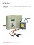
TRACETEK TTDM-128 TraceTek Leak Detection Master Module Installation Instructions General Information Please read these instructions carefully and keep them in a safe place (preferably close to the TTDM-128) for future reference. These instructions must be followed carefully to ensure proper operation. The TTDM-128 Leak Detection Master Module has been designed specifically for use with TraceTek sensing cables, point sensors, sensor interface modules and relay modules. The TTDM-128 can directly monitor up to 1500 m (5000 ft) of sensing cable, and large networks of remote leak detection modules. K TE E AC TR An external disconnect device and appropriate branch circuit protection (no more than 20 amp rating) should be provided for the TTDM-128. The disconnect device should be clearly marked as such. Follow all national and local codes and regulations applicable to the installation. Approvals AND CERTIFICATIONS Tools Required • Drill or hole punch for electrical conduit entries TYPE NM • Phillips (cross-head) screwdriver • Small flat-head screwdriver General Signaling Equipment 76LJ Installation Items (not supplied) • Wall fasteners for surface mounting (four screws) Storage Keep the module in a dry place prior to installation to avoid possible damage to internal components. Product Information TTDM-128 115 Vac +15%, –20%; 50/60 Hz 230 Vac ±10%; 50/60 Hz TTDM-128-24V 24 Vac +5%, –35% Power consumption 10 VA for TTDM-128 9 VA for TTDM-128-24 V Installation categories Overvoltage Category II, Pollution Degree 2 Built-in relays Number: Three (Service, Leak, Fault) Type:DPDT Rating: 5 A at 250 Vac/24 Vdc Storage temperature –18°C to 60°C (0°F to 140°F) Operating temperature 0°C to 50°C (32°F to 122°F) Enclosure Type 12; IP 54 Humidity 5% - 95% non-condensing Max Altitude 2000 m (6,562 ft) 24 Vdc ±20% Important Warnings and Notes The following icons are used extensively throughout this manual to alert you to important that affect safety and to important notes that affect the proper operation of the warnings unit. Be sure to read and follow them carefully. THERMAL BUILDING & INDUSTRIAL HEAT TRACING SOLUTIONS EN-TraceTekTTDM128-IM-H57341 01/15 1 / 12 Safety Instructions WARNING: The installation, adjustment or repair of the TTDM-128 involves risk of contact with potentially lethal voltages and currents. These Installation Instructions are for use by qualified personnel only. To reduce the risk of electric shock, do not perform any servicing other than that specified in the Installation Instructions unless you are qualified to do so. Refer servicing to qualified personnel. The enclosure door should remain closed while the TTDM-128 unit is operational. Servicing or adjustments should not be performed while the circuits are energized. Explanation of Symbols used on this equipment The following symbols are used to identify parts and provide warnings for the TTDM-128 unit. CAUTION: Risk of Electric Shock. Circuits are live. Disconnect unit before servicing. Do not remove cover. Do not open cover while energized. No user serviceable parts inside. Refer servicing to qualified personnel. GROUND- This symbol identifies the equipment ground points. Direct Current Alternating current This symbol identifies important safety warnings and notes that affect the proper operation of the unit. WARNING: Shock hazard. Shut off power before opening enclosure door. TRACETEK LCD display 1 LEDs with icons 2 Test key 3 Silence key 4 Reset key 5 Menu keys 6 User Interface board 7 4—20 mA board (optional) 8 Sensor Interface board 9 Motherboard bk Power supply board bl Fuse (500 mA, 250 V, time delay) bm Power cable plug and socket bn Voltage Selector Switch bo Spare fuse bp Ground/earth stud bq Gland plate br Fault relay cable plug and socket bs Leak relay cable plug and socket bt Service relay cable plug and socket ck 4—20 mA port plug and socket cl RS-232/485 host port plug and cm socket Sensing cable plug and socket cn RS-485 TraceTek Network Plug co & Socket Ribbon cable cp cq Host port RS-232/485 selector cr9 pin RS-232 socket csReset pins ctVolume adjustment dkLCD contrast adjustment PL indicates power limited circuits THERMAL BUILDING & INDUSTRIAL HEAT TRACING SOLUTIONS EN-TraceTekTTDM128-IM-H57341 01/15 2 / 12 Installing the TTDM-128 Important: The TTDM-128 is an electronic unit. During installation, take the following precautions to avoid damage to its electronic components: • To avoid damage to the unit, store the TTDM-128 module in its cardboard box until construction is complete. • Handle with care, avoid mechanical damage. • Keep the electronics dry. • If handling circuit boards, hold them by their edges to avoid physical contact with electronic components. • Avoid exposure to static electricity. • Avoid contamination with metal filings, liquids, or other foreign matter. Select the mounting position. Choose a location indoors where the module will be protected from the elements and temperature extremes. Follow all national and local codes and regulations applicable to the installation. • Remove the module from its carton. Do not remove the protective film from the membrane on the front of the unit. • Open the enclosure door using a flat-blade screwdriver or a coin. WARNING: Ignition hazard. Do not mount the TTDM-128 unit in a hazardous location. Sensing cable connected to the TTDM-128 may (subject to approvals restrictions) be located in hazardous locations, but the module itself must be in an ordinary area. Important: The TraceTek sensing circuit is power limited, so the TraceTek leader or jumper cable and the power supply cable must not run in the same conduit. Mounting the Enclosure Install the enclosure using four screws (selected by installer) in the prepunched 8 mm (5/16-inch) mounting holes with centers as shown in Figure 3. If plastic plugs are in the mounting holes, remove them. Make sure the rubber elastomeric washers (provided in the shipping box) are aligned to seal around the mounting screws to maintain the TYPE 12 and IP54 ratings. Figure 3 300 mm (11.81 in) 261 mm (10.26 in) 20 mm (0.79 in) 200 mm (7.87 in) 240 mm (9.45 in) THERMAL BUILDING & INDUSTRIAL HEAT TRACING SOLUTIONS 20 mm (0.79 in) mounting hole (four places) 8 mm (5/16 in) Attachment points for motherboard (four places) EN-TraceTekTTDM128-IM-H57341 01/15 3 / 12 Making Enclosure Entries Using the Removable Gland Plate The removable gland plate br on the bottom edge of the enclosure provides a location to feed wires into the enclosure (Figure 4). The plate is attached with eight screws. Unscrew these to remove the gland plate, then you can drill or punch holes in the gland plate appropriate for your application. There is sufficient width for up to five 1/2-inch or M20 holes. Remove all metal filings and dust from the gland plate before remounting. Take care not to damage the gasket on the gland plate. You must secure the gland plate ground wire to the chassis ground lug after remounting the gland plate. Figure 4 Grounding wire to attach to ground lug in enclosure terminal 62. Gasket Screws Gland plate Connecting the Power Cable and Relays WARNING: Shock hazard. Disconnect from live voltage prior to opening enclosure door. TTDM-128 Power Supply Connection • Open door of TTDM-128 enclosure. • For 110/220 Vac power supply: select the appropriate voltage using the voltage selector switch bo. TTDM-128-24 V Power Supply Connection IMPORTANT: For proper operation of the TTDM-128-24 V, use a power supply whose output is electrically isolated from the incoming line power and ground. • Each TTDM-128-24 V requires a separate isolated power supply. THERMAL BUILDING & INDUSTRIAL HEAT TRACING SOLUTIONS EN-TraceTekTTDM128-IM-H57341 01/15 4 / 12 TTDM-128 and TTDM-128-24 V Power Wiring Connection • There is no internal mechanism for de-energizing the power. Installer must provide individual branch circuit breaker (no more than 20 amp rating and short circuit rating of minimum 5 kVA) within line of sight. • Pass the power cable through the gland plate adapter/bushing into the enclosure. • Connect the ground/earth wire to the ground/earth stud bq. • The ground/earth stud is marked with this symbol: IMPORTANT: Proper grounding/earthing of the TTDM-128 enclosure is important to avoid the possibility of electromagnetic interference. • Remove the power cable plug from the socket bn on the power supply board bl. • Connect the power supply wires to the power cable plug. Use L2 for neutral, if present. IMPORTANT: The terminals can accept wires 10 AWG (4.7 sq. mm) or smaller. We recommend 12 AWG (3.0 sq. mm) wires, with branch circuit protection sized accordingly. Cable should have a temperature rating of 65°C minimum. • Insert the power cable plug back into the socket bn on the power supply board bl. 110/220 Vac power supply Do not exceed maximum voltage rating Use L2 for neutral, if present. VAC IN 24 V power supply Do not exceed maximum voltage rating THERMAL BUILDING & INDUSTRIAL HEAT TRACING SOLUTIONS EN-TraceTekTTDM128-IM-H57341 01/15 5 / 12 Connect the alarm relays. The TTDM-128 has three relays, for service ck, leak bt, and fault bs. Each relay provides two Form-C relay contacts, and normally open and normally closed contacts are both provided. The relays are de-energized to indicate an alarm condition. The illustration shows the relay status in the alarm (de-energized) state. The illustrations that follow show how relays can be jumpered together to allow remote monitoring of the TTDM-128 status with only a single pair of wires. The TTDM-128 de-energizes its relays to signal an alarm condition. Therefore, loss of power, as well as any other type of alarm, would signal the remote alarm. IMPORTANT: The relay plugs can accept wires 10 AWG (4.7 sq. mm) or smaller. We recommend 18 AWG (1.0 sq. mm) wires. Cable should have a temperature rating of 65°C. IMPORTANT: Maximum load for relays is 5 A. SERVICE RELAY LEAK RELAY FAULT RELAY Alarm on open circuit Relays wired in series Monitoring circuit (alarm on open circuit) Alarm on closed circuit Relays wired in parallel Monitoring circuit (alarm on closed circuit) THERMAL BUILDING & INDUSTRIAL HEAT TRACING SOLUTIONS EN-TraceTekTTDM128-IM-H57341 01/15 6 / 12 Testing the Module Test after supplying power. • Close and latch the enclosure door. • Supply power to the unit. When power is supplied, the green LED illuminates, and the unit goes through a series of self-tests. After the start-up sequence is complete, the module should report a fault alarm (this is normal; there is no sensing cable attached). Press the red Silence key to silence the audible alarm. Verify that the display appears similar to the one shown here (the time and date may be different): If anything other than the above occurs, check all connections. If unit still does not appear to operate properly, contact a TraceTek representative for assistance. • Press the Test button. The module conducts a number of self-tests. • If the tests are successfully completed, record this on the installation record. • Turn off the power supply to the unit. Test with TTDM-128 test plug. • To conduct a more complete test, use the TraceTek TTDM-CTP test plug (packed in a plastic bag in the TTDM packaging). Insert the plug into the sensing cable socket cn on the sensor interface board 9. • Close and latch the enclosure door. • Supply power to the unit. When power is supplied, the unit will again go through a series of self-tests. If the test plug is in the sensing cable socket, after the module completes the start-up sequence it should sound and display a leak alarm. Press the Silence key to silence the audible alarm. The red Leak LED and green Monitoring LED should both be illuminated, and the screen display should appear similar to the one shown here (depending on the setting). • If anything other than the above occurs, check all connections. If unit still does not appear to operate properly, contact a TraceTek representative for assistance. • If the test is successfully completed, record this on the installation record. • Turn off the power supply to the unit. • Remove the TTDM-CTP test plug and store it in a secure place for future use. • If not immediately connecting the sensing cable, or TraceTek network, close and latch the enclosure. Depending on the units selected, the leak distance should be within the values below: feet: 527 to 548 ft meters: 160 to 168 zones: 11 THERMAL BUILDING & INDUSTRIAL HEAT TRACING SOLUTIONS EN-TraceTekTTDM128-IM-H57341 01/15 7 / 12 Connect the Sensing Cable If the TTDM-128 will be used to monitor a sensor directly, follow these instructions to connect the sensor to the TTDM-128. If the TTDM-128 is being used only as a network master, skip to Connecting the TraceTek Network. Prepare sensing cable. Ensure that the sensing cable has been installed and tested in accordance with the instructions provided with the cable. Make connections. WARNING: Shock hazard. Disconnect from live voltage prior to opening enclosure door. • Confirm that power to the unit has been shut off. • Open the enclosure door. • Feed the end of the TraceTek Leader Cable (or Jumper Cable) through the gland plate br adapter/bushing into the enclosure. • Remove the sensor cable plug cn from the socket on the sensor interface board 9. • Connect the four color-coded wires to the Sensor Interface plug. Important: Observe the color coding. If wires are not connected to the proper terminals, the leak detection system cannot operate properly. • Insert the sensing cable plug back into the socket on the Sensor Interface Board 9. Black Yellow Green Red SENSOR CABLE PL Install zener barrier, if applicable. When sensing cable will be located in Class I, Division 1 (Zone 0 or Zone 1 in Europe) hazardous locations, approval agencies require that the sensing cable be protected with a zener barrier between the sensing cable and the TTDM-128 module. Contact TraceTek to select the proper zener barrier. When installing a zener barrier, wire it in accordance with the instructions provided with the kit. Ordinary Area TTDM-128 Class I, Division 1 (Zone 0 or Zone 1 in Europe) Hazardous Location TRACETEK Zener barrier Sensing cable Jumper cable Leader or jumper cable THERMAL BUILDING & INDUSTRIAL HEAT TRACING SOLUTIONS EN-TraceTekTTDM128-IM-H57341 01/15 8 / 12 Connecting the TraceTek Network If the TTDM-128 will be used as the network master in a TraceTek network, follow these instructions to connect the communication wiring. IMPORTANT: Some TraceTek network configurations will require different connections for the communication wiring. Please refer to the TTDM-128 User Manual (H56853) for further details. Prepare communication cable. Ensure that the communication cable has been installed and tested. Make connections. WARNING: Shock hazard. Disconnect from live voltage prior to opening enclosure door. • Confirm that power to the unit has been shut off. • Open the enclosure door. • Feed the end of the communication cable through the gland plate br adapter/bushing into the enclosure. • Remove the J10 cable plug co from the socket. • Connect the positive wire to terminal 3 (485+) and the negative wire to terminal 4 (485–) of the J10 cable plug. • Connect the shield wire to the round lug bq. IMPORTANT: Observe the polarity. If wires are not connected to the proper terminals, the leak detection system cannot operate properly. • Insert the J10 cable plug back into the socket co. • Place the positive and negative wire in the Ferrite clamp. Do not place the shield wire inside the clamp. Close the clamp by securing its latch to the snaps. PL SHIELD RS-485 (–) RS-485 (+) Ferrite clamp RS-485 cable to next TraceTek module. THERMAL BUILDING & INDUSTRIAL HEAT TRACING SOLUTIONS EN-TraceTekTTDM128-IM-H57341 01/15 9 / 12 Connecting to a Host Computer There are 3 ways to connect the TTDM-128 to a host computer: hard-wired RS-232, hard-wired RS-485, or standard modular RS-232 cable. For permanent installations, the hard-wired method is recommended (either RS-232 or RS-485 as necessary). The modular RS-232 cable should be used only for temporary connections by trained technicians. Make connections. WARNING: Shock hazard. Disconnect from live voltage prior to opening enclosure door. • Confirm that power to the unit has been shut off. • Open the enclosure door. • Feed the end of the communication cable through the gland plate br adapter/bushing into the enclosure. • Remove the J13 cable plug cm from the socket. For RS-232 connection: • Connect the RX, TX, RTS, CTS and DGND wire to terminals 5, 6, 7, 8 and 10 respectively. • Set the host port selector switch cq on the User Interface board 7 to the RS232 position. For RS-485 connection: • Connect the positive wire to terminal 5 (RX/A) and the negative wire to terminal 6 (TX/B). Set the host port selector switch cq on the User Interface board 7 to the RS485 position. • Connect the shield wire to the grounding lug bq. • Insert the J13 cable plug back into the socket cm. PL SHIELD DGND CTS RTS TX RX RS-232 cable PL THERMAL BUILDING & INDUSTRIAL HEAT TRACING SOLUTIONS SHIELD RS-485 (–) RS-485 (+) RS-485 cable EN-TraceTekTTDM128-IM-H57341 01/15 10 / 12 Start-Up and System Testing Power up the system. After connections are complete, supply power to the unit. The unit will go through a series of selftests, and then display the system status. If the sensing circuit is complete and free of leaks or other problems, only the green Monitoring LED will illuminate, and the LCD display will appear similar to that shown at right: If this is not the case, you can find additional information in the TTDM-128 Operation and Maintenance Manual (H56853) supplied with the module. Commissioning. Your system should be commissioned by an authorized TraceTek representative including creation of a System Map. The System Map is a crucial part of a TraceTek locating system. The System Map is normally completed at the time the leak detection system is commissioned. The System Map is defined for each SIM sensor circuit, typically an as-built drawing of the sensor cable/ component layout with reference to readily identifiable landmarks, preferably with actual distance measurements every 5m (16ft) throughout the system. The System Map should be constructed with simulated leak events at convenient locations along the leak detection circuit. The reported leak distance (from TTDM-128) is recorded on the System Map for every tested location. The TTDM-128 will give the point along the sensing cable at which liquid has been detected; the map is essential to show its physical location. Important: Store hardware and documentation supplied with the TTDM-128 in a secure place for later use (commissioning, connecting interfaces, operating). If the equipment is used in a manner not specified by the manufacturer, the protection provided by the equipment may be impaired. Important: Before creating a leak alarm for System Mapping purposes, the sensing cable parameters RG Resistance and YB Resistance should be stable and equal +/- 2%, and cable parameter Sense Res should be greater than 10,000 kohms. THERMAL BUILDING & INDUSTRIAL HEAT TRACING SOLUTIONS EN-TraceTekTTDM128-IM-H57341 01/15 11 / 12 WWW.pentairTHERMAL.COM NORTH AMERICA Europe, Middle East, Africa Asia Pacific Latin America Tel:+1.800.545.6258 Fax:+1.800.527.5703 Tel:+1.650.216.1526 Fax:+1.650.474.7215 [email protected] Tel:+32.16.213.511 Fax:+32.16.213.603 [email protected] Tel:+86.21.2412.1688 Fax:+86.21.5426.2937 [email protected] Tel:+713.868.4800 Fax:+713.868.2333 [email protected] Pentair and TraceTek are owned by Pentair or its global affiliates. All other trademarks are the property of their respective owners. Pentair reserves the right to change specifications without prior notice. © 2003-2015 Pentair. THERMAL BUILDING & INDUSTRIAL HEAT TRACING SOLUTIONS EN-TraceTekTTDM128-IM-H57341 01/15 PN 000000079 12 / 12