1
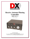
INSTRUCTIONS
QF-1A AUDIO FILTER
Your new audio filter is the product of several years
of development by the originator of commercial
active audio filters for shortwave communications
(1972).
Each filter is thoroughly tested twice before
shipment. Please read the instructions carefully for
best results, and save them for future reference. If
you require adaptors or other parts not supplied,
please obtain these locally as we do not stock them.
A. INITIAL HOOKUP
Plug the QF-1A into your receiver s phone jack or
speaker output. Any impedance is O.K. Obtain an
adaptor if size is not compatible. Connect any
impedance phones or speaker to the rear-panel
phone jack output. To avoid hum or distortion with
Hi-Fi headphones, use a series resistor of about 46
ohms. (See In case of trouble .)
The filter input may also be connected to the rcvr
speaker wires. Just be sure the input cable shield
(connected to QF-1A chassis) is connected to the
grounded speaker wire; otherwise, there may be
hum.
Note: This is rare, but some Barlow-Wadley radios
and CB sets require a load resistor across their
speaker or phone output for a DC return. The filter s
high input impedance does not provide this. Try a
resistor in the range of 10 to 100 ohms installed in
the radio across the output being used. Otherwise the
set may appear to be dead, as the output stage bias is
wrong.
1. Auxiliary Notch Frequency
A notch rejects a narrow band of frequencies, such
as a whistle, or a code station. The Aux Notch is
present at all times. To effectively disable it, set it to
either 80 or 11,000 Hz. The Aux Notch is very wide,
for easiest tuning, and very deep. Its 135:1 frequency
range is by far the widest ever available for
communications, and should cover any signal.
2. Function Select Switch (PK, NOTCH, LP, HP)
This switch and the Selectivity/Frequency controls
adjust the response of the main filter (all but the Aux
Notch). PEAK (bandpass) passes a narrow band of
frequencies, and rejects others -- just the opposite of
NOTCH. LOWPASS passes low frequencies, while
rejecting high frequencies (e.g. hiss). HIGHPASS is
the opposite of LOWPASS: it passes high
frequencies, while rejecting low frequencies. An
exception occurs at high selectivity, where
LOWPASS and HIGHPASS take on some of the
characteristics of PEAK.
3. Selectivity Control
In PEAK, this control determines the filter
bandwidth. Peak bandwidth as narrow as 14 Hz
(- 3 dB) or 20 Hz (-6 dB) is available at 300 Hz. The
bandwidth gradually increases to 20 Hz at an 800 Hz
center frequency, and reaches a few hundred Hz at
the highest frequency setting (2500 Hz). This
bandwidth increase is deliberate and makes for
easiest tuning. At min. Sel., the filter is almost flat.
B. FAMILIARIZATION
In NOTCH and LOWPASS, the panel suggests the
best settings. More selectivity rotation (clockwise)
makes the notch narrower, and shallower, hence
harder to tune: in LOWPASS and HIGHPASS,
excessive selectivity rotation can lead to ringing at
some frequencies.
The filter selects or rejects certain frequency
components of signals you tune in. This allows it to
reject undesired signals, such as noise and
interference, while passing the desired signal, so
long as the noise and signal are not on the same
frequency. This frequency selection/rejection is
optimized with 5 controls:
The ideal theoretical best selectivity for least
peaking in LOWPASS and HIGHPASS occurs when
the selectivity control is rotated about two-thirds the
frequency control, i.e. if the frequency control is
rotated 50%, rotate the selectivity control about
30%. However, this rule of thumb should be
broken under many conditions (see Tables 1 and 2).
4. Frequency Control
This tunes the main filter frequency from about 250
to 2500 Hz, the entire usable communications range
for voice, CW, and digital (RTTY, SSTV, etc.)
signals.
5. In/Out Switch
This turns off the AC power and bypasses the filter.
There is an unavoidable click when thrown due to
the power supply charging or discharging. The filter
draws less than 1/2 watt if left on accidentally.
Note: Volume is adjusted with your receiver s gain
control. Gain at high selectivity in PEAK (and LP) is
high, and very little noise comes through; so keep
receiver gain low under these conditions to avoid
saturation of the QF-1A power amp (distortion)
when the desired CW signal comes through!
C. USEFUL ADJUSTMENTS
See Tables 1 and 2.
D. IN CASE OF TROUBLE
We carefully test all filters. Most problems occur
when first used due to improper connection (read
instructions again) or misunderstanding of operation.
The following are most common:
HUM OR DISTORTION WHEN USING
HEADPHONES
Hum generated in the QF-1A is normally barely
audible with a speaker unless you place your ear
within a few inches of the speaker. However, hum
and distortion may be troublesome if you use 4-8
ohm Hi-Fi headphones, which are much too
sensitive. To cure this (and improve Hi-Fi
listening as well!) connect a 47 ohm resistor in series
with this type of headphones.
HUM WITH SPEAKER.
Usually this comes from your receiver. The QF-1A
loads the receiver output much less than a speaker or
phones. Therefore, you may find that switching the
filter on produces hum, although no hum is heard
in the filter off (bypass) position. This may simply
be because the filter is not loading down the receiver
as much. To see if the filter is really causing the
hum, pull the filter input jack out of your receiver
(not the same as switching to bypass!). If the hum
goes away, or is reduced to nothing, with the filter
input jack lying on the table, then the hum is coming
from the receiver, and being emphasized because of
the light loading by the filter input. Several solutions
are indicated: 1) Check for good contact between the
filter input plug and receiver jack. 2) Especially if
the receiver phone jack is on an auxiliary speaker,
try connecting some hookup wire between the
speaker case and the receiver/xcvr chassis, or
between the filter chassis. 3) Try connecting a 10 to
47 ohm resistor across the receiver phone jack or
other output to load it down.
PICKUP OF YOUR TRANSMITTED SIGNAL
This should be extremely rare with the QF-1A, as
layout and RF bypass caps are excellent, and show
no sign of RF at 2 KW with the antenna 20 feet
away and the cover off, in our tests. However, some
shacks, especially using end-fed antennas in the
shack, and/or extreme RF on the 115 VAC AC line,
may possibly interfere with any audio gear.
Solutions in this case are: 1) Plug the filter into an
outlet away from the transmitter. 2) Move the filter
physically a few feet away from the strong RF
source; experiment. 3) Try connecting pieces of
hookup wire between various units in the shack to
eliminate ground loops, e.g., xcvr/linear, linear/filter,
spkr case/filter, etc. until all possible combinations
have been tried. 4) Use a good waterpipe ground to
your rig. 5) Try an L/C RFI AC line filter available
at a local Radio Shack or CB store. 6) Read more in
radio handbooks. The above measures are rarely
necessary as the QF-1A has been designed for use in
high-power transmitting stations. So, if you have a
problem, you must solve it in your shack; and all
shacks are different.
BATTERY OPERATION DESIRED
Locate the rectifier diodes, D1 and D2, on the
schematic. These are directly forward of the right
transformer screw (as viewed from the front of the
unit). Connect +12 to +14 VDC to the right side of
either diode (the side with the band on the diode).
Connect the battery ground to the filter chassis
ground. Note: reversal of battery polarity, even for
an instant, will burn out the filter -- not covered by
warranty.
Table 1. USEFUL ADJUSTMENTS
Your QF-A can imitate the response of virtually any filter with fixed responses, at any price, and give an infinite
number of other useful responses as well! Truly, if the QF-1A can t pull the signal out, no other filter can either!
However, the QF-1A s flexibility means that even experienced operators will need some time to learn how to best
use all the controls. The following table will aid you. IMPORTANT: Don t give up on a setting because it doesn t
seem to help. Tomorrow, with different conditions, this setting may turn out to be just what s needed.
Condition
Useful Adjustments (See Note 1 for Aux Notch setting)
Desired CW
Signal
PEAK. Casually listen with 7 to 10 o clock selectivity, yielding a relatively wide 80 to 120 Hz
bandwidth. Adjust frequency for desired CW note. Gradually increase selectivity and touch-up
frequency to match conditions. There is much confusion among hams about ringing of a CW
filter, mainly caused by mfrs. of filters without the narrow ultimate selectivity of the QF-1A.
Basically, here is the truth: ALL filters will produce audible ringing at bandwidths below 80-120
Hz (and many poorly designed filters will ring even at wider bandwidths). So the only way to
eliminate ringing is to use wide bandwidth (low selectivity on the QF-1A). On the other hand, a
CW signal has a bandwidth less than 10-20 Hz, so a very narrow filter can pass the entire CW
signal and greatly reduce interference -- but at the expense of ringing. The QF-1A gives you
your choice (at considerable increase in manufacturing complexity). High selectivity will be
found to be invaluable in very heavy QRM or pileups, allowing you to hear signals inaudible at
wider bandwidths, but high selectivity is not as useful in thermal noise. Note that gain at the
peak increases at high selectivity, while blasting when the desired signal comes through the
narrow slot .
LOWPASS. Produces an effect similar to PEAK at high selectivity. Ignore LOWPASS Sel.
panel markings for CW reception. If you listen to CW at a low note (more than 12 o clock freq.
rotation), you may find that you prefer LOWPASS. But LOWPASS is wider, and gain varies
more.
Voice Signal
with Splatter
LOWPASS. Adjust selectivity as on panel: rotate frequency for best compromise between
rejection of splatter and rejection of desired signal. Frequency rotation beyond 8-10 o clock
rejects desired signal heavily, making it sound bassy. The idea is to find the best cutoff
frequency, to maximize copy. If splatter completely covers the desired signal, or if two signals
are on the same frequency, the situation is impossible, and no known method of signal
processing will work.
Voice Signal
(Moderate
Interference)
PEAK. This position, at moderate selectivity of 7-9 o clock, and frequency adjusted for best
copy, can sometimes clean up signals and give more presence .
HIGHPASS. Full frequency rotation (250 Hz) and 3-5 o clock selectivity, along with AUX
NOTCH at 9 o clock, can give greater presence under some conditions. To reject lows or
hum, set frequency as little as 11 o clock, with selectivity rotated about 2/3 of frequency.
Table 1 (Continued)
Multiple
Whistles or
CW
Normally, AUX NOTCH is used. But the MAIN NOTCH is deeper (to 70 dB), and can be made
narrower (at high selectivity). Use notch Sel. shown on panel. The notch is not as deep at high
selectivity, so use minimum Sel. rotation consistent with least rejection of desired signal. Note:
To help find the notch frequency, momentarily switch to PEAK at high Sel., peak the whistle,
then switch back to notch at moderate selectivity. Touchup the main frequency slightly, since
PEAK and NOTCH may not track perfectly. For two whistles, or CW, or teletype QRM, use
both main and Aux Notch.
Weak CW
An AC voltmeter, or scope, across the filter output is a big help in peaking weak CW.
Strong Signal
A flat response is approximated with the Aux Notch at 11,000 and main filter as follows:
PEAK: Freq. = 12 o clock; Sel.= Min.
NOTCH: Freq. = 2500; Sel. = Max.
LOWPASS: Freq. = 2500; Sel. = Min.
HIGHPASS: Freq. = 250; Sel. = 2 o clock
Note: Even with these settings the filter contains additional fixed rolloffs below 250 Hz and
above 2500 Hz, so is not intended for Hi-Fi applications, only communications.
TTY, SSTV
and Misc.
For TTY, SSTV, etc. reject low frequencies using HIGHPASS: Sel. and Freq. about 10-12
clock (experiment). Or use notches to reject CW, etc.
You will no doubt discover other settings for voice, CW, etc. not in this table, but useful under
some conditions, or with your own ear preferences. There is a conceivable use for almost all of
the infinite number of settings under some conditions, and with some signals.
Line Noise,
Ignition, or
Other Static
The QF-1A will produce some improvement due to narrower bandwidth, especially on CW, but
nothing dramatic on voice. The only really good solutions are a good IF NOISE BLANKER in
your receiver, or a beam antenna. Even IF blankers are generally ineffective except on car
ignition noise -- and may help a little on line noise. Audio NOISE LIMITERS (not to be
confused with IF BLANKERS) can be built for the cost of two 5-cent diodes (see Radio
Amateur s Handbook), but we found them to cause distortion and be virtually worthless for
noise, so they are not included, despite their negligible cost.
NOTE 1: AUX NOTCH SETTING. It s usually best to leave the Aux Notch at 11,000 until the main filter is
adjusted for best results. Set it at about 9 o clock for voice, where it rejects a wide band of hiss and highfrequency whistles. Set it to reject any loud whistle or CW at other frequencies.
Table 2. CONDENSED VERSION OF Table 1
Condition
Function
Selectivity
Main Frequency
CW
Voice Splatter
Voice
Voice
Whistle / Other QRM
PEAK
LOWPASS
PEAK
HIGHPASS
REJECT QRM
Two Whistles
NOTCH
8 o clock or more
As on panel
7 to 9 o clock
3 to 5 o clock / 11 up
(Use Aux Notch to reject
whistle)
As on panel
SSTV, TTY
HIGHPASS
10 to 12 o clock
For best copy
7 to 11 o clock
For best clarity
250 Hz / 11 up
(Use Aux Notch to reject
whistle)
To reject whistle (plus
Aux Notch)
Same as Sel. (or use
notches if whistles are
problem)
E. WARRANTY AND RETURNS
CHECKLIST WHEN RETURNING A UNIT:
We back our products better than most companies -not just 90 days, but one full year. Our Attorney
insists we supply the following lengthy description:
1. Enclose definite proof of purchase date, as
described above with ANY return, unless you
simply wish repair out of warranty. In this case,
enclose a check or MO for a minimum of $17.00, as
described above, plus $15 outside North America.
LIMITED ONE YEAR WARRANTY: Autek
Research warrants to the original consumer
purchaser that its products shall be free of defects in
workmanship and materials from one year from date
of purchase.
WARRANTY LIMITATIONS: This limited
warranty does not cover, and we are not responsible
for, any product which has been modified by the
owner, or any malfunction or failure resulting from
improper use, improper applied voltage, improper
service or repair by the owner or his agent, or from
abuse, neglect, accident, lightning damage, fire, use
contrary to instructions, or other causes beyond the
control of Autek Research. This warranty is made to
the original consumer purchaser only, and is
effective only upon presentation of documented
evidence of provable date of purchase.
This warranty covers only Autek products, used for
purposes as advertised. We are not responsible for
incidental or consequential damages. Some states do
not allow exclusion or limitation of incidental or
consequential damages, so the above limitation or
exclusion may not apply to you. This warranty gives
you specific legal rights, and you may also have
other rights which vary from state to state.
2. ANY RETURN not complying with the above
instructions will waste time and is subject to an
additional $3 charge for correspondence, or return,
COD, without any action taken. FOLLOW THE
ABOVE INSTRUCTIONS.
3. Enclose a detailed description of the problem and
above checks, proof of purchase, date, etc. INSIDE
the package. Do not send separate correspondence
explaining that you are returning the unit. Put
everything INSIDE THE PACKAGE.
4. Allow 1-3 weeks for any repair, plus up to 2
weeks two-way shipping in USA. Please don t write
about the status of the repair before this time. (Only
1 in 2000 packages are lost by shippers.)
F. IF WRITING:
1. Most ask about things already covered in
instructions. Read again carefully. They represent
virtually everything we know about characteristics,
hookup problems, etc. There is little else to tell.
2. Always state your purchase date.
3. Always give full details. Your rig, phones or
speaker, exact hookup, and detailed symptoms. Most
letters are much too vague. We want to help you, but
have no idea of the condition of your rig, your
ability to follow the instructions, or what you ve
tried, and no desire to carry on extensive
correspondence. Include all details in the first letter.
4. We will not comment on any modifications to the
QF-1A, as inventive hams would make this a fulltime job.
5. Enclose a self addressed stamped envelope for a
much speedier reply; O.K. to fold envelope.
6. Not necessary to write before returning a unit.
Simply follow instructions ( ) carefully.
G. ALIGNMENT
The circuit has two alignments. Neither should
require adjustment unless disturbed, especially the
Main filter Tracking alignment, which is quite noncritical. The Aux Notch Depth alignment is more
critical and sensitive.
Keep the input signal low, to avoid saturation. A
scope is recommended at the filter output for most
accurate alignment, although an AC voltmeter, or
even the ear, can produce acceptable results.
The alignment frequency of 800 Hz produces best
results over the entire filter range. However, if you
desire best results at another frequency far removed
from 800 Hz, i.e. 2000 Hz, it may be better to align
the filter at the frequency of most interest.
1. Aux Notch Depth Alignment. Adjusted by the
10K trim-pot near the left side of the circuit board -behind the Aux Notch pot and slightly to the right.
Feed in a signal at approx. 800 Hz (not critical).
Your receiver s calibrator beat note, or a signal
generator may be used. 800 Hz is an average
frequency for CW reception, and occurs at about 10
clock rotation of the MAIN frequency. Then adjust
the trim pot for minimum signal. Now touch up the
Aux Notch freq. and repeat the trim pot adjustment
for minimum signal. Continue adjusting until no
further improvement is noted.
2. Main Filter Tracking Alignment. There are two
complete filters in series in the main filter. These
filters are adjusted to track by this alignment. The
alignment trim pot is directly behind the main (2502500 Hz) frequency control on the right side of the
board. Feed a signal at approx. 800 Hz (not critical)
into the filter. Select peak and rotate Selectivity
full (20 Hz setting). Set the Aux Notch at 11,000.
Peak the signal with the main freq. control. Then
adjust the trim pot for max. response. Readjust the
main freq. and trimpot for max. response. Repeat
until no further improvement in response is noted.
Note: Alignment is the responsibility of the owner,
even if needed during warranty. Our minimum
$17.00 service charge applies to any return simply
requiring alignment.
H. LATE NOTES
If you wish the QF-1A to drive a speaker in
bypass you must obviously connect the QF-1A
input to a rig output which is capable of driving a
speaker. (Some headphone outputs, but not all, can
drive a speaker). When the filter is on virtually
any high-level rig output can drive it. However, in
bypass the rig s output is connected directly to the
QF-1A output jack, so the rig must be capable of
driving the speaker, if any, connected to the QF-1A
output.
The QF-1A has proved to be extremely reliable.
Despite a 1 year warranty, we ve had periods of up
to 3 months where not a single unit has failed on
return! However, we emphasize that MOST
RETURNS have nothing wrong with them. Please
be sure there is a problem before any return.
RF pickup seems to have been virtually eliminated.
However, approximately every 4 months, someone
reports RFI. If pickup should occur, we emphasize
again that there is nothing wrong with your unit, and
any problem must be solved in your shack. (See In
case of trouble .) Reports are that all owners have
been successful, usually by eliminating ground
loops, or using an AC line filter, in these rare
stubborn cases.