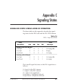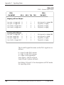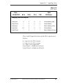
1
FXO+ DUAL VOICE OPTION MODULE
Part Number 1200103L2
&
FXO+ DUAL VOICE PLUG-ON BOARD
Part Number 1200104L2
USER MANUAL
61200.103L2-1B
March 1997
Table of Contents
901 Explorer Boulevard
P.O. Box 140000
Huntsville, AL 35814-4000
Phone: (205) 963-8000
© 1997 ADTRAN, Inc.
All rights reserved.
Printed in U.S.A.
Table of Contents
FEDERAL COMMUNICATIONS COMMISSION
RADIO FREQUENCY INTERFERENCE STATEMENT:
This equipment has been tested and found to comply with the limits for a Class A digital device,
pursuant to Part 15 of the FCC Rules. These limits are designed to provide reasonable protection
against harmful interference when the equipment is operated in a commercial environment. This
equipment generates, uses, and can radiate radio frequency energy and, if not installed and used
in accordance with the instruction manual, may cause harmful interference to radio frequencies.
Operation of this equipment in a residential area is likely to cause harmful interference in which
case the user will be required to correct the interference at his own expense.
Shielded cables must be used with this unit to ensure compliance with Class A FCC limits.
Changes or modifications to this unit not expressly approved by the party
responsible for compliance could void the user’s authority to operate the
equipment.
Table of Contents
FEDERAL COMMUNICATIONS COMMISSION (FCC)
INFORMATION
FCC regulations require that the following information be provided to the customer in this manual:
1.
This equipment complies with Part 68 of the FCC rules. The required label is affixed to
the bottom of the chassis.
2.
If your telephone equipment (FXO+) causes harm to the telephone network, the
telephone company may discontinue your service temporarily. If possible, they will notify
you in advance. But if advance notice is not practical, you will be notified as soon as
possible. You will be advised of your right to file a complaint with the FCC.
3.
Your telephone company may make changes in its facilities, equipment, operations, or
procedures that could affect the proper operation of your equipment. If they do, you will
be given advance notice so as to give you an opportunity to maintain uninterrupted
service.
4.
If you experience trouble with this equipment (FXO+), please contact ADTRAN Customer
Service for repair/warranty information (see the end of this manual). The telephone
company may ask you to disconnect this equipment from the network until the problem
has been corrected or until you are sure the equipment is not malfunctioning.
5.
This unit contains no user serviceable parts.
6.
The following information may be required when applying to your local telephone
company for switched line facilities:
Service
REN/SOC
FIC
USOC
Loop Start
Ground Start
0.3B/9.0F
0.1A/9.0F
02LS2
02GS2
RJ11C
RJ11C
7.
The REN and FCC registration number are indicated on the label. The ringer equivalence
number (REN) is used to determine how many devices can be connected to your telephone
line. In most areas, the sum of the RENs of all devices on any one line should not exceed
five (5.0). If too many devices are attached, they may not ring properly.
8.
On the circuit board of this equipment is a label that contains, along with other information, the FCC registration number and ringer equivalence number (REN) for the equipment requested. Provide this information to your telephone company.
9.
The equipment may not be used on public coin service provided by the telephone
company. Connection to party lines is subject to state tariffs.
Table of Contents
AFFIDAVIT REQUIREMENTS FOR CONNECTION TO DIGITAL SERVICES
• An affidavit is required to be given to the telephone company whenever digital terminal equipment without encoded analog content and
billing protection is used to transmit digital signals containing encoded
analog content which are intended for eventual conversion into voice
band analog signals and transmitted on the network.
• The affidavit shall affirm that either no encoded analog content or
billing information is being transmitted or that the output of the device
meets Part 68 encoded analog content or billing protection specifications.
• End user/customer will be responsible to file an affidavit with the local
exchange carrier when connecting unprotected CPE toa 1.544 Mbps or
subrate digital services.
• Until such time as subrate digital terminal equipment is registered for
voice applications, the affidavit requirement for subrate services is
waived.
Table of Contents
AFFIDAVIT FOR CONNECTION OF CUSTOMER PREMISES
EQUIPMENT TO 1.544 MBPS AND/OR SUBRATE DIGITAL SERVICES
For the work to be performed in the certified territory of _______________
(telco name)
State of ________________
County of ________________
I, _____________________________ (name), _____________________
(business address), ____________________ (telephone number) being
duly sworn, state:
I have responsibility for the operation and maintenance of the terminal equipment
to be connected to 1.544 Mbps and/or ________ subrate digital services. The
terminal equipment to be connected complies with Part 68 of the FCC rules except
for the encoded analog content and billing protection specifications. With respect
to encoded analog content and billing protection:
( ) I attest that all operations associated with the establishment, maintenance, and
adjustment of the digital CPE with respect to analog content and encoded billing
protection information continuously complies with Part 68 of the FCC Rules and
Regulations.
( ) The digital CPE does not transmit digital signals containing encoded analog
content or billing information which is intended to be decoded within the telecommunications network.
( ) The encoded analog content and billing protection is factory set and is not
under the control of the customer.
I attest that the operator(s)/maintainer(s) of the digital CPE responsible for the
establishment, maintenance, and adjustment of the encoded analog content and
billing information has (have) been trained to perform these functions by successfully having completed one of the following (check appropriate blocks):
( ) A. A training course provided by the manufacturer/grantee of the equipment
used to encode analog signals; or
( ) B. A training course provided by the customer or authorized representative,
using training materials and instructions provided by the manufacturer/grantee of
the equipment used to encode analog signals; or
Table of Contents
( ) C. An independent training course (e.g., trade school or technical institution)
recognized by the manufacturer/grantee of the equipment used to encode analog
signals; or
( ) D. In lieu of the preceding training requirements, the operator(s)/maintainer(s)
is (are) under the control of a supervisor trained in accordance with _________
(circle one) above.
I agree to provide _________________ (telco's name) with proper documentation to
demonstrate compliance with the information as provided in the preceding
paragraph, if so requested.
_________________________________Signature
_________________________________Title
_________________________________ Date
Transcribed and sworn to before me
This ________ day of ________, 199___
_________________________________
Notary Public
My commission expires:
_________________________________
Table of Contents
CANADIAN EQUIPMENT LIMITATIONS
The Industry Canada Certification label identifies certified
equipment. This certification means that the equipment meets
certain telecommunications network protective, operational,
and safety requirements. The Department does not guarantee
the equipment will operate to the user's satisfaction.
Before installing this equipment, users should ensure that it is permissible to be
connected to the facilities of the local telecommunications company. The equipment
must also be installed using an acceptable method of connection. In some cases, the
company's inside wiring associated with a single line individual service may be
extended by means of a certified connector assembly (telephone extension cord). The
customer should be aware that compliance with the above conditions may not
prevent degradation of service in some situations.
Repairs to certified equipment should be made by an authorized Canadian maintenance facility designated by the supplier. Any repairs or alterations made by the user
to this equipment, or equipment malfunctions, may give the telecommunications
company cause to request the user to disconnect the equipment.
Users should ensure for their own protection that the electrical ground connections
of the power utility, telephone lines and internal metallic waterpipe system, if
present, are connected together. This precaution may be particularly important in
rural areas.
Users should not attempt to make such connections themselves,
but should contact the appropriate electric inspection authority, or an electrician, as appropriate.
The Load Number (LN) assigned to each terminal device denotes the percentage of
the total load to be connected to a telephone loop which is used by the device, to
prevent overloading. The termination on a loop may consist of any combination of
devices subject only to the equipment that the total of the LNs of all devices does not
exceed 100.
The ringer equivalence number (REN) assigned to each terminal adapter is used to
determine the total number of devices that may be connected to each circuit. The sum
of the RENs from all devices in the circuit should not exceed a total of 5.0.
Table of Contents
Table of Contents
Chapter 1. Introduction ..................................................................................... 1
FXO+ Dual Voice Overview ................................................................................ 1
Functional Description ................................................................................. 2
Features .................................................................................................... 2
FXO+ Option Module Specifications .................................................. 3
Physical Description ...................................................................................... 4
Warranty and Customer Service ........................................................................ 5
Chapter 2. Installation ....................................................................................... 7
Unpack and Inspect .............................................................................................. 7
Shipped by ADTRAN ................................................................................... 7
Provided by Customer .................................................................................. 7
Installing The FXO+ Dual Voice Option Module ............................................. 8
Modules With Hot Replaceable Label on Back Panel ............................... 8
Modules Without Hot Replaceable Label on Back Panel ......................... 8
Placement of the Option Module ................................................................ 9
Power Connection ......................................................................................... 9
Wiring ........................................................................................................... 10
Power Up Testing and Initialization ................................................................ 11
Successful Self Test ...................................................................................... 11
Failed Self Test ............................................................................................. 11
Operation Alarms ........................................................................................ 11
Chapter 3. Operation ........................................................................................ 13
Overview .............................................................................................................. 13
Menu Structure ............................................................................................ 13
Menu Operation .......................................................................................... 13
FXO+ Menu Items .............................................................................................. 15
Port Status ..................................................................................................... 15
2-Wire Status ......................................................................................... 16
View Signaling Bits .............................................................................. 16
Port Config (Port Configuration) .............................................................. 17
Mode ...................................................................................................... 18
RX LVL (TLP) (Receive Level/Transmit Level Point) .................... 19
TX LVL (TLP (Transmit Level/Transmit Level Point) ................... 19
Fault Resp (Fault Response) ............................................................... 19
Port Utility .................................................................................................... 20
Port Test ........................................................................................................ 21
61200.103L2-1
FXO+ Dual Voice Option Module User Manual
i
Table of Contents
1 kHz Tone ............................................................................................ 21
VIEW SIG BITS (View Signaling Bits) ............................................... 22
SET TX SIGNAL (Set Transmit Signal) ............................................. 22
SET 2-W OUTPUT (Set 2-Wire Output) ............................................ 22
TSU Features Used With FXO+ Options ......................................................... 23
Factory Restore ............................................................................................ 23
Run Self Test ................................................................................................. 23
Appendix A. FXO+ Option Card Menu Tree .............................................. 25
Appendix B. FXO+ Failure Messages ........................................................... 27
Failure Messages at Power-Up ......................................................................... 27
Appendix C. Signaling States ........................................................................ 29
Signaling States versus Mode of Operation ................................................... 29
List of Figures
Figure 1-1 FXO+ Dual Voice Option Module .................................................. 4
Figure 2-1 Installing Option Module ................................................................ 9
Figure 3-1 TSU 100 Main Menu ....................................................................... 14
Figure 3-2 Port Status Submenus .................................................................... 15
Figure 3-3 2-Wire Status Display ..................................................................... 16
Figure 3-4 View Signaling Bits Display .......................................................... 16
Figure 3-5 Port Configuration Submenus ...................................................... 17
Figure 3-6 Port Utility Submenus .................................................................... 20
Figure 3-7 Port Test Submenus ........................................................................ 21
Figure 3-8 View Signaling Bits Display .......................................................... 22
Figure A-1 FXO+ Option Card Menu Tree ..................................................... 25
List of Tables
Table 2-A 2-Wire Voice Pinout Connection .................................................... 10
Table 3-A Port Configuration Parameters ...................................................... 17
Table 3-B Port Test Parameters ......................................................................... 22
Table C-A FXO+ Loop Start Mode .................................................................. 29
Table C-B FXO+ Ground Start Mode .............................................................. 30
Table C-C DPT Mode ........................................................................................ 31
ii
FXO+ Dual Voice Option Module User Manual
61200.103L2-1
Chapter 1. Introduction
Chapter 1
Introduction
FXO+ DUAL VOICE OVERVIEW
The FXO+ Dual Voice (FXO+) option module is one of
the option modules available for use with the
ADTRAN TSU 100/120/600. The FXO+ module
provides two 2-wire voice-grade interfaces serving as
the loop termination for central office line current and
ringing voltage.
The FXO+ module emulates a telephone or station
interface. It responds to signaling from the digital
signal, level 1 (DS1) stream by providing loop closure
or ring ground to the 2-wire interface. The condition
of tip-ground and ringing on the 2-wire interface is
converted to signaling out the DS1 stream. The FXO+
may serve as the office side of a foreign exchange
FXO/FXS application. The FXO+ may be used with
the ADTRAN FXS+ to implement message-waiting
with analog message-waiting phones that need -150
VDC to light the message lamp. The FXO+ module
features on-hook data transmission for passing Caller
ID data from the 2-wire interface to the DS1 stream.
When the FXO+ is used in the dial pulse terminate
(DPT) mode with E&M signaling on the DS1 stream, it
extends the central office side of an analog direct
inward dial (DID) trunk to the customer premises.
The FXO+ may be used to connect to the station side
of a private branch exchange (PBX). Signaling and
interfaces comply with portions of EIA/TIA-464-A
61200.103L2-1
FXO+ Dual Voice Option Module User Manual
1
Chapter 1. Introduction
and AT&T Pub. 43801, and FCC Part 68. The FXO+
option module also accepts the FXO+ plug-on board to
provide up to four FXO+ functional ports per option
slot used, as well as accepting other plug-on modules.
The FXO+ plug-on module may be plugged onto any
existing TSU option module.
Functional Description
The FXO+ is designed to fit in the option slot of the
TSU 100/120/600 and is subject to its operation and
control. The FXO+ is configured from the front panel
of the TSU 100/120/600 or by an external personal
computer (PC) program (T-Watch). The internal
menus for its configuration are a part of the FXO+
module and are automatically installed when the
FXO+ is plugged into the unit.
Features
The FXO+ Dual Voice option module has the following features:
• Each 2-wire port operates at 64 kbps
• Menu configurable transmit (TX) and receive (RX)
levels (transmit level points - TLPs)
• FXO, FXO message waiting, and DPT operating
modes
• Passes Caller ID data from the 2-wire interface to the
T1
• Ground Start or Loop Start 2-Wire Supervision
• Extensive testing capabilities:
- RX and TX signal bit monitoring
- Busy, ringing, message-waiting, and status
monitoring
- Integral 1 kHz tone generation sends test tone
towards near or far end
- Manual control of TX A and B signal bits
- Manual control of 2-wire interface supervision
output
• Adding the FXO+ plug-on board provides the TSU
2
FXO+ Dual Voice Option Module User Manual
61200.103L2-1
Chapter 1. Introduction
100/120/600 with four voice ports in one option slot
• Selectable 2-Wire output for carrier failure
• Full V.34 modem compatible
• Detects and forwards far-end disconnect signals to
ADTRAN FXS+ in FXS mode.
FXO+ Option Module Specifications
The FXO+ Dual Voice option module conforms to the
following specifications:
61200.103L2-1
Voice Channels
Two (four with plug-on
module installed)
Transmission Levels
TX: +8 to 0 dB TLP, 1 dB
steps
RX: 0 to -8 dB TLP, 1 dB
steps
Frequency Response
2-wire Impedance
2-wire ERL
2-wire SRL
THL ERL
THL SRL
Longitudinal Bal
RX Idle Channel Noise
TX Idle Channel Noise
300 to 3400 Hz (+/- 1.0 dB)
600 Ω + 2.15 µF
≥20 dB
≥15 dB
>25 dB
≥20 dB
>52 dB
<15 dBrnc
<20 dBrnc
Operating Temperature
0° to 45°C, relative humidity, non-condensing
Connector
RJ-45
Tests
Power-on circuit test
Signal Bits Monitoring and
Setting
1 kHz test tone generation
Settable 2-wire port output
state
FXO+ Dual Voice Option Module User Manual
3
Chapter 1. Introduction
Physical Description
The FXO+ is an option module which plugs into the
option slot in the rear of the main unit; see Figure 1-1.
DUAL FXO
PORT X.1
PORT X.3
PORT X.2
Figure 1-1
FXO+ Dual Voice Option Module
The FXO+ rear panel includes a plastic plug over a
cutout for additional connectors. This allows a plugon board to be added to the FXO+ module. The PORT
X.Y indication is linked to the port numbering philosophy of the TSU 100 product family. The X represents
the slot number, and the .Y indicates the port
number. For the TSU 100 application, there is only
one option slot. Therefore the port designations for
the two FXO voice ports will be 1.1 and 1.2. If added,
the plug-on board port designation would be 1.3 and
1.4. These port numbers appear in the front panel
liquid crystal display (LCD) menu displays.
4
FXO+ Dual Voice Option Module User Manual
61200.103L2-1
Chapter 1. Introduction
WARRANTY AND CUSTOMER SERVICE
ADTRAN will replace or repair this product within
five years from the date of shipment if the product
does not meet its published specifications or if it fails
while in service. For detailed warranty, repair, and
return information refer to the ADTRAN Equipment
Warranty and Repair and Return Policy Procedure.
Return Material Authorization (RMA) is required
prior to returning equipment to ADTRAN.
For Service, RMA requests, or more information,
contact one of the numbers at the end of this manual.
61200.103L2-1
FXO+ Dual Voice Option Module User Manual
5
Chapter 1. Introduction
6
FXO+ Dual Voice Option Module User Manual
61200.103L2-1
Chapter 2. Installation
Chapter 2
Installation
UNPACK AND INSPECT
Carefully inspect the FXO+ Dual Voice option module
for any shipping damages. If damage is suspected, file
a claim immediately with the carrier and then contact
ADTRAN Technical Support. If possible, keep the
original shipping container for use in shipping the
FXO+ module back for repair or for verification of
damage during shipment.
Shipped by ADTRAN
The following items are included in the ADTRAN
shipment:
• FXO+ Dual Voice option module
• User Manual (to be inserted into main TSU 100/
120/600 user manual)
Provided by Customer
The customer must provide a cable for connection to
the station.
61200.103L2-1
FXO+ Dual Voice Option Module User Manual
7
Chapter 2. Installation
INSTALLING THE FXO+ DUAL VOICE OPTION MODULE
For ease of replacement, power to the TSU 100/120/
600 may be on when installing or removing the FXO+
Dual Voice option module.
For use in Canada, regulatory compliance requires that the
Transmit Level/Transmit Level Point, TX LVL (TLP), of the
FXO+ Dual Voice option module be set to a value between
+3dB and +8dB inclusive, and that the TSU 100/120/600
be password protected to prevent unauthorized alteration of
the level.
See the chapter Operations for information on setting the
Transmit Level/Transmit Level Point, TX LVL (TLP). See
the TSU 100/120/600 user manual for information about
password protecting the unit.
8
FXO+ Dual Voice Option Module User Manual
61200.103L2-1
Chapter 2. Installation
Placement of the Option Module
Figure 2-1 represents the action required for proper
placement of the option module.
1.
2.
3.
Remove cover plate from the unit rear panel.
Slide option module into the rear panel until it is
positioned firmly against the front of the unit.
Fasten thumbscrews at both edges of the option
module.
Cover Plate
TSU 100/120/600
Option Module
Figure 2-1
Installing Option Module
Power Connection
Each FXO+ module derives power from the base TSU
100/120/600 unit. Power to the TSU 100/120/600 is
supplied by a captive eight-foot power cord.
61200.103L2-1
FXO+ Dual Voice Option Module User Manual
9
Chapter 2. Installation
Wiring
The FXO+ Dual Voice option module offers two
connectors for an analog voice interface. The connectors are universal and accept either an RJ-45 (8-pin) or
an RJ-11 (6-pin modular plug). The pinout is given in
Table 2-A.
The required wiring connection is as follows:
Connector Type (USOC)
Part number
RJ-45
AMP # 555164-1
Table 2-A
2-Wire Voice Pinout Connection
PIN
NAME
DESCRIPTION
5
TIP
Tip lead of 2-wire interface
4
RING
Ring lead of 2-wire interface
1, 2, 3, 4, 5, 6, 7, 8
UNUSED
-
Pins used to mate with the FXO+ connector are as
follows:
10
RJ-11
Tip
Ring
pin 4
pin 3
RJ-45
Tip
Ring
pin 5
pin 4
FXO+ Dual Voice Option Module User Manual
61200.103L2-1
Chapter 2. Installation
POWER UP TESTING AND INITIALIZATION
The FXO+ option module executes a partial self test
during the power up sequence, as described in the
TSU 100/120/600 manual. A full self test can be
activated from the Test menu. No initialization input
is required. Any previously configured setting for the
FXO+ is restored automatically upon power up.
Successful Self Test
The green OK LED, located with the Module LEDs on
the front panel, turns on when a successful self test is
completed and the configuration is successfully
restored. See the chapter Operation in the main user
manual.
Failed Self Test
If the FXO+ module fails one or more of the self tests,
a message is displayed in the LCD during power up.
See the TSU 100/120/600 user manual. Specific
failures of the FXO+ module are identified in the
appendix FXO+ Failure Messages in this manual.
Operation Alarms
The red ALARM LED with the Module LEDs on the
front panel turns on when an alarm condition is
detected.
61200.103L2-1
FXO+ Dual Voice Option Module User Manual
11
Chapter 2. Installation
12
FXO+ Dual Voice Option Module User Manual
61200.103L2-1
Chapter 3. Operation
Chapter 3
Operation
OVERVIEW
The FXO+ module is controlled as part of the TSU
100/120/600 using the same methods as described in
the user manual.
See the TSU 100/120/600 user manual for descriptions
of front panel indicators and buttons.
Menu Structure
When an option module is installed in the TSU
100/120/600, the unit adds it to the list of available
options under the Port menu items. These menu items
are shaded in the limited overview of the TSU 100
menu shown in Figure 3-1. (The appendix of the TSU
100 user manual contains a complete menu diagram.)
Menu Operation
An option module must be selected from the listing in
one of the Port menu options before any option
module menus are applicable. With the cursor on one
of the Port menu items, press Enter to display a list of
the currently installed option modules. To activate
menus for the FXO+ option module, scroll through the
list to display X.1 FXO+ and press Enter. (The X
represents the slot number, and .1 identifies the port
number.)
61200.103L2-1
FXO+ Dual Voice Option Module User Manual
1
Chapter 3. Operation
Once the option module is selected, the FXO+ menus
appear as a subset of, and operate the same as, menus
for the main unit. Use the up and down Arrows to
place the cursor on the desired item and press Enter to
display the first two submenu choices.
1)NI PERF REPORTS
1)STATUS
2)CONFIG
TSU 100
MAIN MENU
2)NI ERRORS
1)NETWORK (NI)
3)ACTIVE ALARMS
2)UNIT
4)VIEW HISTORY
3)MAP XCHNG
5)PORT STATUS
4)MAP IN USE A (B)
6)REMOTE PORT
5)DS0 MAP A
7)CLEAR PORT ALM
6)DS0 MAP B
7)PORT CONFIG
1)TIME/DATE
2)FACTORY RESTORE
3)SET PASSCODE
3)UTIL
4)UNIT ID
5)SOFTWARE REV
4)TEST
1)NETWORK TESTS
6)PORT UTILITY
2)RUN SELF TEST
3)PORT TEST
4)CANCEL TEST
Figure 3-1
TSU 100 Main Menu
2
FXO+ Dual Voice Option Module User Manual
61200.103L2-1
Chapter 3. Operation
FXO+ MENU ITEMS
The FXO+ menus are accessed from, and operate the
same as, menus for the TSU 100/120/600. The FXO+
items are submenu choices of those four Main menus,
as shown in Figure 3-1. For information on Factory
Restore and Run Self Test see TSU Features Used With
FXO+ Options in this chapter.
The FXO+ menu items:
• Port Status
• Port Configuration
• Port Utility
• Port Test
Port Status
Port Status, a submenu of TSU 100/120/600 Main
menu item Status, displays active status information
about the FXO+ interface.
When Port Status is displayed, place the cursor on it
and press Enter to display the first available port.
Scroll to select 1.1 FXO+ and press Enter to activate
either of the submenus shown in Figure 3-2.
1)NI PERF REPORTS
1)STATUS
2)NI ERRORS
3)ACTIVE ALARMS
4)VIEW HISTORY
5)PORT STATUS
6)REMOTE PORT
2W STATUS
1.1 FXO+
VIEW SIG BITS
7)CLEAR PORT ALM
Figure 3-2
Port Status Submenus
61200.103L2-1
FXO+ Dual Voice Option Module User Manual
3
Chapter 3. Operation
2-Wire Status
There are three information fields, Busy, Ringing, and
Message-Waiting (MW). See Figure 3-3. An asterisk
(*) indicates an item is active.
Figure 3-3
2-Wire Status Display
Busy
An asterisk is present if loop current is flowing
through the 2-wire circuit.
Ringing
An asterisk is present if ringing voltage is being
applied to the 2-wire input.
MW (Message-Waiting)
An asterisk is present if 150 VDC message-waiting
voltage is applied between tip and ring.
View Signaling Bits
View Sig Bits is used to view the status of the RX and
TX signaling bits in the DS1 stream. See Figure 3-4.
The status of both the A and B bits is displayed.
Figure 3-4
View Signaling Bits Display
4
FXO+ Dual Voice Option Module User Manual
61200.103L2-1
Chapter 3. Operation
Port Config (Port Configuration)
Port Configuration, a submenu of TSU 100/120/600
main menu item Configuration, is used to configure the
FXO+ option module. The submenu items shown in
Figure 3-5 are used to configure the parameters.
2)CONFIG
7)PORT CONFIG
1)MODE
1.2 FXO+
2)RX LVL (TLP)
3)TX LVL (TLP)
4)FAULT RESP
Figure 3-5
Port Configuration Submenus
The unit displays the first of seven submenu items.
Table 3-A identifies the available selections for Port
Configuration. Continue with standard operating
procedures.
Table 3-A
Port Configuration Parameters
MENU ITEM
PARAMETER CHOICES
MODE
FXS-LS, FXO-GS, FXO-LSMW, DPT
RX LVL (TLP)
--8 dB --> 0 dB, 1 dB steps *(--3 dB)
TX LVL (TLP)
FAULT RESP
0 dB -->+8 dB, 1 dB steps *(+3 dB)
*Normal, Seized
*Factory Default
61200.103L2-1
FXO+ Dual Voice Option Module User Manual
5
Chapter 3. Operation
Mode
Mode sets the type of 2-wire to T1 signaling used.
Choices include:
FXO_LS (FXO loop-start)
This mode detects the presence of ringing voltage on a
2W analog line with battery. The status of this ringing
signal is passed on out the T-span. The FXO+ also
provides loop-closure in response to signaling being
received on the T-span. The FXO interface looks like a
telephone to the analog line that it terminates. Linecurrent dropout is also detected at the end of a call
(disconnect supervision) and is passed to the far-end
FXS card.
FXO_GS (FXO ground-start)
This mode is used when interfacing to or extending
ground start analog central office trunks. Ringing
voltage and tip-ground is detected by this card and
passed out the T-span. Incoming signaling on the
T-span will determine if ring ground or loop closure is
asserted on the 2W interface. Ground start lines are
often used with PBX and key systems to reduce the
possibility of incoming and outgoing calls on a trunk.
FXO_LSMW (FXO loop-start message waiting; used
in ESF framing only)
This mode is the same as FXO_LS with the exception
that 150-volt message-waiting voltage is detected and
that information is passed out the T-span to the farend FXS+ card. Message waiting operation allows an
analog message-waiting telephone to be placed at a
remote location and connected through T-span.
6
FXO+ Dual Voice Option Module User Manual
61200.103L2-1
Chapter 3. Operation
DPT (dial-pulse terminate)
This mode allows analog DID (direct inward dial)
trunk interfaces on a PBX to be interfaced to a T-span.
In the DPT mode, the FXO+ card detects battery
polarity reversal and passes this information out the Tspan. The FXO+ responds to signaling on the T-span
by opening or closing the loop. These functions allow
incoming calls on the T-span using E&M signaling to
be terminated on an analog port using loop-reverse
battery signaling.
RX LVL (TLP) (Receive Level/Transmit Level Point)
RX LVL (TLP) sets the RX direction transmission level
points (TLP). The TLP is indicated in dB and the
relative loudness is indicated by a bar graph display.
Settings change immediately as the bar graph is
scrolled.
Choice range: – 8 dB –> 0 dB, in 1 dB steps.
TX LVL (TLP) (Transmit Level/Transmit Level Point)
TX LVL (TLP) sets the TX direction transmission level
points (TLPs). The TLP is indicated in dB and the
relative loudness is indicated by a bar graph display.
Settings change immediately as the bar graph is
scrolled.
Choice range: +0 dB –> –8 dB, in 1 dB steps.
Fault Resp (Fault Response)
Fault Response, Normal or Seized, determines the 2wire output during a carrier alarm. For a network
alarm, the 2-wire trunk would appear busy if set for
seized. If set for Normal, no seizure occurs.
Choices: Normal and Seized.
61200.103L2-1
FXO+ Dual Voice Option Module User Manual
7
Chapter 3. Operation
Port Utility
Port Utility, a submenu of the TSU 100/120/600 main
menu item Utilities (UTIL) displays the current
software information for each port installed in the
unit. This information is required when requesting
assistance from ADTRAN Technical Support or when
updates are needed.
When Port Utility is displayed, place the cursor on it
and press Enter to display the first available port. See
Figure 3-6.
1)TIME/DATE
2)FACTORY RESTORE
3)SET PASSCODE
3)UTIL
4)UNIT ID
5)SOFTWARE REV
6)PORT UTILITY
1)SW REVISION
1.1 FXO+
2)CMD MODE
Figure 3-6
Port Utility Submenus
Display 1.1 FXO+ (scroll to display if necessary), and
press Enter. The unit displays the option module
name and the software version installed.
The submenu Port Utility contains a second option,
2)CMD Mode, for the FXO+ module. This option is
reserved for factory use only.
Press Cancel to exit or select another port.
8
FXO+ Dual Voice Option Module User Manual
61200.103L2-1
Chapter 3. Operation
Port Test
Port Test, a submenu of the TSU 100/120/600 Main
menu item Test, activates tests of the selected data
ports. Selecting the FXO+ displays tests available for
this option module. See Figure 3-7.
4)TEST
1)NETWORK TESTS
1)1 KHZ TONE
2)RUN SELF TEST
3)PORT TEST
2)VIEW SIG BITS
1.1 FXO+
4)CANCEL TEST
3)SET TX SIGNAL
4)SET 2W OUTPUT
Figure 3-7
Port Test Submenus
1 kHz Tone
This test injects a 1004 Hz sine wave either toward the
far end (TX DIRECTION toward the T1 network) or
toward the near end (the 2-wire interface on the option
module). This tone may be used for testing or relative
level measurements.
Choices: Off, Near, and Far.
61200.103L2-1
FXO+ Dual Voice Option Module User Manual
9
Chapter 3. Operation
VIEW SIG BITS (View Signaling Bits)
View Sig Bits is used to view the status of the RX and
TX signaling bits in the DS1 stream. See Figure 3-8.
The status of both the A and B bits is displayed.
Figure 3-8
View Signaling Bits Display
SET TX SIGNAL (Set Transmit Signal)
Set TX Signal allows the A and B signal bits in the TX
direction to be forced to a desired state for test.
SET 2-W OUTPUT (Set 2-Wire Output)
Set 2W Output allows the 2-wire voice interface
output to be forced to a desired state for test.
Table 3-B
Port Test Parameters
MENU ITEM
10
PARAMETER CHOICES
1 kHz Tone
Off, Near, Far
View Sig Bits
Display only
Set TX Signal
Off, A=0 B=0, A=1 B=0, A=0 B=1, A=1 B=1
Set 2W Output
Off, Loop Open, Loop Closed, Ring Ground
FXO+ Dual Voice Option Module User Manual
61200.103L2-1
Chapter 3. Operation
TSU FEATURES USED WITH FXO+ OPTIONS
In addition to the FXO+ menu items, two additional
menu items of the TSU 100/120/600 may be operated
in conjunction with the FXO+ option module. These
are Factory Restore and Run Self Test.
Factory Restore
Factory Restore, a submenu of the TSU 100/120/600
Main menu item UTIL (Utilities), restores the factory
installed default setting for all FXO+ option module
parameters.
When Factory Restore is displayed, place the cursor on
it and press Enter. The unit is restored to preset
factory defaults and returns to the Main menu. The
factory default for port configuration parameters is
shown in Table 3-A.
Run Self Test
Run Self Test, a submenu of the TSU 100/120/600
Main menu item Test, executes both the FXO+ internal
test and the TSU 100/120/600 internal test. The
results of the self test are displayed in the LCD. See
the TSU 100/120/600 user manual for additional
information on Self Test.
When Run Self Test is displayed, place the cursor on it
and press Enter to execute the test. The unit continuously changes the display in the LCD window until all
test results are shown.
61200.103L2-1
FXO+ Dual Voice Option Module User Manual
11
Chapter 3. Operation
12
FXO+ Dual Voice Option Module User Manual
61200.103L2-1
Product Support Information
Presales Inquiries and Applications Support
Please contact your local distributor, ADTRAN
Applications Engineering, or ADTRAN Sales:
Applications Engineering
Sales
(800) 615-1176
(800) 827-0807
Post-Sale Support
Please contact your local distributor first. If your local
distributor cannot help, please contact ADTRAN
Technical Support and have the unit serial number
available.
Technical Support
(888) 4ADTRAN
Repair and Return
If ADTRAN Technical Support determines that a
repair is needed, Technical Support will coordinate
with the Return Material Authorization (RMA)
department to issue an RMA number. For information regarding equipment currently in house or
possible fees associated with repair, contact RMA
directly at the following number:
RMA Department
(205) 963-8722
Identify the RMA number clearly on the package
(below address), and return to the following address:
ADTRAN, Inc.
RMA Department
901 Explorer Boulevard
Huntsville, Alabama 35806
RMA # _____________
Appendix A. FXO+ Option Card Menu Tree
Appendix A
FXO+ Option Card Menu Tree
The menu tree for the FXO+ Option Card is provided
in Figure A-1.
1)Port Status
2)Port Config
3)Port Utility
4)Port Test
1)2W Status (Busy Ringing)
2)View Sig Bits (RXA RXB TXA TXB)
1)MODE: FXO_LS, FXO_GS, FXO_LSMW, DPT
2)RX LVL (TLP): -8 dBM to 0 dBM
3)TX LVL (TLP): 0 dBM to +8 dBM
4)FAULT RESP: NORMAL, SEIZED
1)SW Revision
2)Command Mode : 0
1)1 KHZ Tone: OFF, NEAR, FAR
2)View Sig Bits (RXA RXB TXA TXB)
3)Set TX Signal: OFF, AB=00, AB=01, AB=10, AB=11
4)Set 2W Output: OFF, LOOP OPEN, LOOP CLOSED, RING GROUND
Figure A-1
FXO+ Option Card Menu Tree
61200.103L2-1
FXO+ Dual Voice Option Module User Manual
25
Appendix A. FXO+ Option Card Menu Tree
26
FXO+ Dual Voice Option Module User Manual
61200.103L2-1
Appendix B. FXO+ Failure Messages
Appendix B
FXO+ Failure Messages
FAILURE MESSAGES AT POWER-UP
The following messages indicate a probable component failure on the FXO+ Module:
E01 - EPROM CS
EPROM checksum error
E02 - RAM ERR
Static RAM error
E03 - TIP GND
Tip ground detection circuits
E04 - RINGING
Ringing detection circuits
E06 - TEST FAIL
Self test could not finish
E10 - SIGNALING Failure of signal bit transmission
61200.103L2-1
FXO+ Dual Voice Option Module User Manual
27
Appendix B. FXO+ Failure Messages
28
FXO+ Dual Voice Option Module User Manual
61200.103L2-1
Appendix C. Signaling States
Appendix C
Signaling States
SIGNALING STATES VERSUS MODE OF OPERATION
The three tables in this appendix describe the signaling states for the FXO card and the DS-1 PCM stream.
Table C-A
FXO+ Loop Start Mode
FXO+
FXO+
2W OUTPUT
RXA
RXB
TXA
TXB
2W Output
Outgoing call from 2W port
Loop Open
0
X
0
1
No ringing (idle)
Loop Open
0
X
0
0
Ringing
Loop Closed
1
X
0
1
No ringing
Incoming call to 2W port
Loop Open
0
X
0
1
No ringing (idle)
Loop Closed
1
X
0
1
No ringing
The A and B signal bit states on the DS-1 signal are as
follows:
0 = logic 0 is the DS-1 stream
1 = logic 1 is the DS-1 stream
X = value is not significant
Loop Open = telephone on-hook
Loop Closed = telephone off-hook
61200.103L2-1
FXO+ Dual Voice Option Module User Manual
29
Appendix C. Signaling States
Table C-B
FXO+ Ground Start Mode
FXO+
FXO+
2W OUTPUT
RX A
RX B
TXA
TX B
2W INPUT
Outgoing call from 2W port
Loop open, no ring ground
0
1
1
1
No tip ground, no ringing (idle)
Loop open, no ring ground
0
1
0
1
Tip ground, no ringing
Loop closed, no ring ground 1
1
0
1
Tip ground, no ringing
Loop closed, no ring ground 1
1
0
0
Tip ground, no ringing
Incoming call to 2W port
Loop open, no ring ground
0
1
1
1
No tip ground, no ringing (idle)
Loop open, ring ground
0
0
1
1
No tip ground, no ringing
Loop open, ring ground
0
0
0
1
Tip ground, no ringing
1
0
1
Tip ground, no ringing
Loop closed, no ring ground 1
The A and B signal bit states on the DS-1 signal are as
follows:
0 = logic 0 is the DS-1 stream
1 = logic 1 is the DS-1 stream
X = value is not significant
Loop Open = phone on-hook
Loop Closed = phone off-hook
See Tables C-B and C-C for descriptions of FXO mode
for signaling states.
30
FXO+ Dual Voice Option Module User Manual
61200.103L2-1
Appendix C. Signaling States
Table C-C
DPT Mode
FXS+
2W OUTPUT
FXO+
RX A
RX B
TX A
TXB
2W Output
Outgoing call from 2W port
Loop Open
0
X
0
0
Normal battery (idle)
Loop Closed
1
X
0
0
Normal battery
Loop Open
1
X
1
1
Reverse battery (wink)
Loop Open
0/1
X
0
0
Normal battery
X
1
1
Reverse battery (answer)
Loop Closed
1
The A and B signal bit states on the DS-1 signal are as
follows:
0 = logic 0 is the DS-1 stream
1 = logic 1 is the DS-1 stream
X = value is not significant
Loop Open = telephone on-hook
Loop Closed = telephone off-hook
61200.103L2-1
FXO+ Dual Voice Option Module User Manual
31
Appendix C. Signaling States
32
FXO+ Dual Voice Option Module User Manual
61200.103L2-1