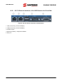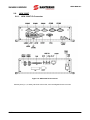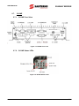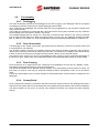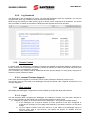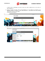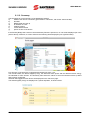
1
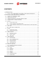
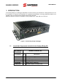
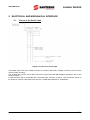
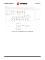
• 15P0460B100 •
SUNWAY BRIDGE
ALL-IN-ONE DATALOGGER, DATA CONCENTRATOR, REMOTE
CONNECTOR SOLUTION
USER MANUAL
Issued on 23/01/2014
R.04
Software Version 4.1.0-0
English
• This manual is integrant and essential to the product. Carefully read the instructions contained herein
as they provide important hints for use and maintenance safety.
• This device is to be used only for the purposes it has been designed to. Other uses should be
considered improper and dangerous. The Manufacturer is not responsible for possible damages caused
by improper, erroneous and irrational uses.
• Elettronica Santerno is responsible for the device in its original setting.
• Any changes to the structure or operating cycle of the device must be performed or authorized by
Elettronica Santerno.
• Elettronica Santerno shall hold no responsibilities for any consequences caused by use of non-original
spare-parts.
• Elettronica Santerno reserves the right to make any technical changes to this manual and to the
device without prior notice. If printing errors or similar are detected, the corrections will be included in
the new releases of the manual.
• The information contained herein is the property of Elettronica Santerno and cannot be reproduced.
Elettronica Santerno enforces its rights on the drawings and catalogues according to the law.
Elettronica Santerno S.p.A.
Via della Concia, 7 - 40023 Castel Guelfo (BO)
Tel. +39 0542 489711 - Fax +39 0542 489722
santerno.com [email protected]
SUNWAY BRIDGE
USER MANUAL
CONTENTS
1. INTRODUCTION ...................................................................................................... 4
1.1. LIST OF THE COMPONENTS INCLUDED IN THE SUNWAY BRIDGE KIT ............ 4
2. ELECTRICAL AND MECHANICAL INTERFACE ..................................................... 5
2.1. PINOUT OF THE SERIAL CABLE ........................................................................... 5
2.2. MOUNTING SUPPORT ........................................................................................... 7
2.3. WIRING DIAGRAM OF THE RS485 SERIAL CABLE .............................................. 8
2.4. POWER SUPPLY WIRING DIAGRAM ..................................................................... 9
2.5. CB 752 ................................................................................................................... 10
2.5.1.
CB 752 FRONT VIEW ................................................................................................. 10
2.5.2.
CB 752 CONTROLS AND INDICATORS .................................................................... 10
2.5.3.
CB 752 EXTERNAL INTERFACES OF THE SBC BOARD ON THE FRONT SIDE ... 11
2.6. ARK 3360F ............................................................................................................ 12
2.6.1.
ARK 3360F IO CONNECTOR ..................................................................................... 12
2.7. B-ONE.................................................................................................................... 13
2.7.1.
B-ONE FRONT VIEW .................................................................................................. 13
2.7.2.
B-ONE STATUS LEDS ................................................................................................ 13
2.8. SERIAL PORTS ..................................................................................................... 14
2.8.1.
ETHERNET PORTS .................................................................................................... 14
2.8.2.
SERIAL PORTS ........................................................................................................... 14
2.8.3.
USB PORTS ................................................................................................................ 14
2.9. FUNCTIONALITY ................................................................................................... 15
2.9.1.
DATALOGGING ........................................................................................................... 15
2.9.2.
DATA CONCENTRATOR ............................................................................................ 15
2.9.3.
DATA PROXYING........................................................................................................ 15
2.9.4.
SUNWAYPORTAL ....................................................................................................... 15
2.9.5.
LOG DOWNLOAD ....................................................................................................... 16
2.10. REMOTE CONTROL ............................................................................................. 16
2.10.1. INVERTER FIRMWARE UPGRADE ........................................................................... 16
2.11. WEB INTERFACE .................................................................................................. 16
2.11.1. LOGIN ........................................................................................................................ 16
2.11.2. SUMMARY ................................................................................................................... 18
2.11.3. DEVICES ..................................................................................................................... 19
2.11.4. CHARTS ...................................................................................................................... 20
2.11.5. ALARMS ...................................................................................................................... 21
2.11.6. CONFIGURATIONS .................................................................................................... 22
2.11.7. DOWNLOADS.............................................................................................................. 22
2/24
USER MANUAL
SUNWAY BRIDGE
2.12. MAINTENANCE ..................................................................................................... 23
3. ANNEX ....................................................................................................................23
3.1. PREREQUISITES FOR REMOTE COMMUNICATIONS ........................................ 23
3.2. REMOTE CONNECTION SECURITY .................................................................... 23
3.3. DATA REFRESH RATE AND EXTERNAL QUERIES ............................................ 24
3/24
SUNWAY BRIDGE
USER MANUAL
1. INTRODUCTION
The Sunway Bridge is a datalogger dedicated to remote monitoring and assistance, offering features such as
the acquisition of measures and indicators, the graphical representation of energy production patterns, the
upgrade of the connected inverter firmware and the log download.
Different hardware versions are available, namely “B-ONE 300”, “ARK 3360” and “CB 752”.
Figure 1: The Sunway Bridge datalogger
1.1.
List of the Components Included in the Sunway Bridge Kit
Part Number
ZZ4600666
SUNWAY BRIDGE KIT
Part Number
Qty
Description
WW6000161
1
Standalone datalogger
SW0000001
1
Datalogger box software
CN0420100
1
Gender changer adapter, 9P M/M
PM0130132
1
Datalogger support
PC1603181
1
RS485 cable for datalogger
CN0420125
1
DB9-DB15 adapter for RS485 cable
Table 1: Components included in the Sunway Bridge Kit
4/24
SUNWAY BRIDGE
USER MANUAL
2. ELECTRICAL AND MECHANICAL INTERFACE
2.1.
Pinout of the Serial Cable
Figure 2: Pinout of the serial cable
The RS485 serial cable uses a DB9 connector for versions “ARK 3360” (straight connection) and “CB 752”
(via the gender changer).
The “B-ONE 300” version uses a DB15 connector requiring the DB9-DB15 adapter supplied in the kit and
shown in Figure 3.
In both the cases above, the RS485 port is terminated with a resistor of approx. 120Ω as follows: directly to
the device for versions “ARK 3360” and “CB 752”; on DB9-DB15 adapter for “B-ONE 300”.
5/24
SUNWAY BRIDGE
Figure 3: Pinout of the DB9/DB15 connector for B-ONE 300
6/24
USER MANUAL
SUNWAY BRIDGE
USER MANUAL
2.2.
Mounting Support
The mounting support is compatible with all the available hardware models.
Key to the drawing:
(1) n.4 holes with M3 thread for B-ONE 300 fastening
(2) n.4 holes with M4 thread for ARK 3360 fastening
(3) n.4 holes with M5 thread for CB 752 fastening
The pregalvanized sheet is 2.5mm thick
Figure 4: Diagram of the datalogger mounting support
7/24
SUNWAY BRIDGE
2.3.
USER MANUAL
Wiring Diagram of the RS485 Serial Cable
Figure 5: Wiring diagram of the RS485 serial cable
8/24
SUNWAY BRIDGE
USER MANUAL
2.4.
Power Supply Wiring Diagram
Figure 6: Wiring diagram of the 24Vdc power supply
The power supply ratings are the following for the different hardware versions:
CB 752
ARK 3360F
B-ONE
6.5..30Vdc
12..24Vdc
18..36Vdc
20W
20W
20W
9/24
SUNWAY BRIDGE
2.5.
USER MANUAL
CB 752
2.5.1.
CB 752 Front View
Figure 7: CB 752 Front View
1
DC IN power connector
2
External connectors of the installed SBC
3
Air openings on the front side
4
Controls and indicators
5
CAN bus interface (not used)
6
Serial port (COM2) RS485
7
Prepared for Serial Port COM3 (not used)
8
DVI-D (Single Link) interface (optional)
9
2x USB ports
10
Rubber feet
2.5.2.
CB 752 Controls and Indicators
Figure 8: CB 752 controls and indicators
1 RESET button
2 Power LED
3 HDD activity LED
4 Power button
10/24
SUNWAY BRIDGE
USER MANUAL
2.5.3.
CB 752 External Interfaces of the SBC Board on the Front Side
Figure 9: CB 752 external interfaces and SBC board
1 LAN1 port (RJ45) (10/100/1000Mbps)
2 LAN2 port (RJ45) (10/100/1000Mbps)
3 2x USB 2.0 port
4 Serial port (COM1), configured as RS232
5 VGA port
11/24
SUNWAY BRIDGE
2.6.
USER MANUAL
ARK 3360F
2.6.1.
ARK 3360F IO Connector
Figure 10: ARK 3360F IO Connector
Comms ports (2, 3, 4 and 6), Mic/Line-In/Line-Out, Lan3 and Digital IOs are not used
12/24
SUNWAY BRIDGE
USER MANUAL
2.7.
B-ONE
2.7.1.
B-ONE Front View
Figure 11: B-ONE front view
2.7.2.
B-ONE Status LEDs
Figure 12: B-ONE Status Leds
13/24
SUNWAY BRIDGE
2.8.
USER MANUAL
Serial Ports
The Sunway Bridge is equipped with at least:
- Two Ethernet interfaces
- One optoisolated RS485 port
- One RS232 serial port
- One VGA port
- Two USB ports.
2.8.1.
Ethernet Ports
The Ethernet ports are marked as LAN1 and LAN2 and have the following features:
- LAN1: this is the main communications port. It is configured by default to operate in DHCP mode,
enabling automatic connectivity to the Santerno server on a network featuring DHCP. If no DHCP is
available on the local network or if a static IP address is preferably set up, the configuration web
interface may be used (see section 2.11 Web Interface).
- LAN2: this a service port used during energy production and technical assistance. Occasionally, it
may be used as a communications port, especially when the devices to be detected are located on a
different subnet than the LAN1. However, this interface is NOT to be connected to the local
communications network, unless agreed upon with Santerno.
Unlike LAN1, LAN2 has two pre-set static addresses assigned by default, i.e. 10.16.0.254 and
169.254.99.99.
The DHCP server is also activated for this interface (LAN 10.16.1.0/24).
2.8.2.
Serial Ports
The two serial ports have different functions:
- Optically isolated RS485 port: performs logging of the devices via Modbus RTU protocol. A
termination resistor is always fitted between signals A and B of the serial link.
- RS232 port: this port hosts a communication terminal. It may be used only by authorised Service
personnel.
2.8.3.
USB Ports
At least three standard USB ports are available. They are dual-purpose:
- communication: a USB/RS485 or USB/RS232 converter may be used if the native serial port is not
intended to be used. The drivers currently pre-installed are “Prolific” and “FTDI”
- service: the USB port allows performing application updates; this functionality is allowed to
authorised Service personnel only.
14/24
SUNWAY BRIDGE
USER MANUAL
2.9.
Functionality
2.9.1.
Datalogging
The main functionality offered by the datalogger is the device logging. The datalogger shall be configured
accordingly by Santerno’s personnel to exploit datalogging functionality.
Once configured, the datalogger will cyclically read from every logged device. Log records are saved to file
every 5 (five) minutes.
The log files are rotated and compressed daily: this means that a new log file is created every day, whilst the
log file relating to the day before is saved in .zip format.
The available logging space is enough for a time span of several months, based on the number of devices
that are logged at the same time. When the logging space is running out, the datalogger deletes the oldest
files; in order not to lose data, it is recommended that the logs be periodically downloaded to a different PC.
2.9.2.
Data Concentrator
The datalogger is also a data concentrator: this means that any data item is stored to an internal cache until
it is replaced by a new data item.
This operating mode is devised for integrated systems with external SCADAs performing high frequency
queries; they are always returned the stored value and are not enabled for the readout of the actual device,
in order to ensure the maximum throughput and the minimum latency for the external queries.
The protocol to be used for this service is the Modbus TCP/IP, using the proper commands depending on
the device to query. Please refer to the Data Refresh Rate and External Queries section for further details.
2.9.3.
Data Proxying
Once the devices to be logged have been configured on the datalogger, this will act as a Modbus “router”,
propagating read and write instances to the physical devices.
This service is available via the Remote Sunway software using a proprietary protocol based on TCP/IP. For
that reason, it must be used only for technical assistance and/or configuration needs, not for production
setup.
This service also enables local or remote changes to all the parameters of all the devices configured on the
datalogger.
2.9.4.
SunwayPortal
Once configured and properly connected to the Internet and the Santerno servers, the datalogger will send a
snapshot of the system status to the SunwayPortal, thus updating the plant status to the Santerno webportal.
The status snapshot is sent every 15 minutes. Only Santerno personnel may change the status snapshot
interval.
15/24
SUNWAY BRIDGE
2.9.5.
USER MANUAL
Log Download
The datalogger is also a standard FTP server. The user and password to enter are “logreader”; you can use
a popular FTP client (e.g. Filezilla) to easily download the stored logs.
Because logs are stored to a folder which is given a random name composed of 32 characters, you should
refer to the date of creation of the folder to identify the latest logs that have been recorded.
2.10. Remote Control
In remote mode, the datalogger is constantly monitored and updated via dedicated Santerno applications to
ensure maximum safety and optimum efficiency. Whenever required, the Service personnel may access the
connected device for maintenance purposes.
The connection to the Internet must be established and the Sunway Bridge is to be properly configured to
exploit the remote assistance feature.
2.10.1. Inverter Firmware Upgrade
The inverter firmware upgrade in local and/or remote mode is allowed to Santerno personnel only.
The inverters must be connected to the datalogger through the RS485 cable. Upgrade via Ethernet is not
currently supported.
2.11. Web Interface
Data display and datalogger configuration is made available by a safe and handy web interface.
2.11.1. Login
The web interface allows configuring the datalogger and viewing its contents. You just need a browser to
carry out any operation. Do the following to access the web interface for the first time:
1) configure your laptop on the same subnet as the datalogger’s. There are two available options:
a. if the datalogger has a valid IP address on LAN1 (because it has been configured or
acquired from a DHCP) set your laptop either statically or via DHCP so that it is on the same
subnet
b. set your laptop in DHCP mode and connect it to the LAN2 of the datalogger using an
Ethernet cable. After a few seconds, your laptop will acquire an address from the
10.16.1.0/24 network.
16/24
USER MANUAL
SUNWAY BRIDGE
In either case, the datalogger will have at least one valid IP address that can be used, the
DATALOGGER_IP.
2) Launch a browser and enter “https:// DATALOGGER_IP” in the address bar. Example: if the
datalogger address is 192.168.1.1, enter “https://192.168.1.1”. Press Send, ignore the certificate
validity warning and press Send again.
The following mask appears:
3) Enter “user” as the username and “user” as the password to log in. The following mask appears:
17/24
SUNWAY BRIDGE
USER MANUAL
2.11.2. Summary
The homepage is a brief summary of the datalogger settings:
a)
status of the remote connection (green means “connected”, red means “disconnected”)
b)
test date
c)
RS485 serial port set up
d)
IP address on LAN1
e)
software version
f)
current date and time
g)
power on time of the device
If the Sunway Bridge has not been commissioned by Santerno personnel, no unit will be displayed (as in the
picture above); otherwise, a screen similar to the following will be displayed (non significant data):
Five Sunway TG inverters are configured with Modbus IDs from 1 to 5.
The inverter status, the alarms tripped (if any), the delivered active power and the delivered active energy
are indicated for each inverter. The Summary also shows the values of the environmental sensors (if fitted
and correctly configured).
Granular data logged for each device are displayed on the “Devices” page.
The alarms tripped (if any) are displayed in a yellow dropdown, as shown below:
18/24
USER MANUAL
SUNWAY BRIDGE
2.11.3. Devices
Access the page to display the logged devices grouped as drop-down menus.
Click on the drop-down menus to expand them and view their readouts. The timestamp in the bottom left
corner in each drop-down menu indicates the latest refresh time.
The pictures below are given as an example.
Starting from version 4.1.0-0, an attribute for each monitored device has been added. This attribute points
out the status of the communications with the Sunway Bridge and can be viewed in each drop-down menu
next to the name of the device.
When the Sunway Bridge detects a reading failure for a device exceeding a given threshold, the device is
marked as “unreachable”.
The Sunway Bridge will then periodically check if the device can be reached again. The Sunway Bridge will
resume normal operation when the readout failures drop below the preset threshold.
The device status may be one of the following:
- responsive: indicates that the device is always responsive
- warning: indicates that no response has been sent by a device to the latest queries
- demoted: indicates a device whose failure rate is above the threshold
- resuming: indicates that the device is resuming normal operation
19/24
SUNWAY BRIDGE
USER MANUAL
2.11.4. Charts
Three different measures may be graphically represented. You just need to select the measures from the
check-boxes and press the “Build chart” button. The system will create a graphic similar to the graph below
(non significant data):
Each curve is identified by a unique name and colour as given in the graph key.
The syntax name is DEVICE[ID_MODBUS](MEASURE): in the picture above, for instance,
“ST170X[24](M064)” relates to measure M064 of a Sunway TG inverter at Modbus address 24.
The Y axes are automatically scalded based on the pattern concerned and the order of magnitude of the
data concerned to avoid confusion. In the figure above, energy (rightmost Y axis) ranges from 639000 to
641000 and the IGBT temperature (leftmost Y axis) ranges from 10 to 22. Only automatic scaling of the axis
ensures that such different data are correctly viewed.
You can do the following for each individual graph:
-
-
20/24
delete a curve and draw a new one: just click on the curve from the graph key. After
removing/adding a new curve, the graph will be dynamically recreated based on the new data
entered
view the punctual value of a data item: a tooltip pops up when the mouse is passed over the value
(see picture above)
print the graph by pressing the Print command in the bottom right corner
save the graph as a PDF, SVG, PNG, JPG file. The connection to the Internet must be established
to exploit this service, which is run on an external server.
USER MANUAL
SUNWAY BRIDGE
2.11.5. Alarms
The Alarm screen summarises the alarms tripped (if any) from the logged devices. Expand the drop-down
menu to view the alarms details.
Example (non significant data):
21/24
SUNWAY BRIDGE
USER MANUAL
2.11.6. Configurations
The user may change the networking configuration of LAN1 as well as the local configurations being used to
set the IP address and change the time zone respectively.
Make sure that the connection to the Internet is established to get synchronisation with Santerno’s servers,
thus ensuring the greatest accuracy in log records.
2.11.7. Downloads
This page shows the link to the FTP site provided by the Sunway Bridge: just click the Downloads menu to
be redirected to the logs, that can be downloaded from the browser as well.
An external client is recommended for quicker download.
As an alternative, you can download the logs to a USB memory stick: just insert the memory stick and press
“Download”.
22/24
USER MANUAL
SUNWAY BRIDGE
2.12. Maintenance
The datalogger is designed to operate 24 hours a day, 7 days a week, thus reducing maintenance to a
minimum.
Every month, make sure that the datalogger may be regularly accessed from the browser and that the log
files are correctly written. If this is not the case, please contact Elettronica Santerno Customer Service.
Change to configuration settings, software updates or hardware upgrades are not allowed unless clearly
stated in this manual.
3. ANNEX
3.1.
Prerequisites for Remote Communications
The following prerequisites are required for the connection of the datalogger to Santerno servers:
- the minimum band shall be 64 Kbit/s, i.e. the band for GPRS connection. However, at least 200
Kbit/s connectivity is recommended for quicker data sending and prompt remote assistance. Any
type of Internet connection is supported, such as: GPRS, 3G, fibre optics, ADSL, HDSL, satellite,
wimax
- the datalogger utilizes TCP connections to the output port or to address IP 213.92.109.16 or to
77.238.26.176/28; if a firewall is activated, the filter traffic rules are to be adjusted accordingly
- DNS and NTP protocols shall not be filtered (public servers may be configured)
- when using a private DNS, the names resolving to private IP addresses shall be allowed (i.e.
networks 192.168/16, 172.16/16 and 10/8)
- the connection to the Internet shall be “straight”, i.e. with no proxy.
Using private network 10.0.0.0/8, even if used with smaller net masks, is forbidden in order to avoid conflicts
with the remote networks used by Santerno remote monitoring services.
Failure to do so will affect the full functionality of the device. Please contact Elettronica Santerno if using
private network 10.0.0.0/8 is required.
3.2.
Remote Connection Security
The datalogger is a client, so no input port is required on the plant, thus ensuring maximum safety.
The physical login is protected by the SSH protocol. The access privileges are granted to Santerno
Engineering staff only.
Every communication instance begins a SSL session with bidirectional certificate authentication and
renegotiates a 128-bit BF-CBC key every hour; SHA1 is the hash used for every HMAC authentication.
Forwarding between Ethernet interfaces is disabled to ensure that Santerno personnel is forbidden to access
the customer’s LAN.
The maximum safety level, especially for corporate LANs, is obtained if the datalogger is part of a DMZ.
23/24
SUNWAY BRIDGE
3.3.
USER MANUAL
Data Refresh Rate and External Queries
Santerno recommends that the following setup should be used to integrate external SCADAs (or any other
master):
- Limit to up to 3 (three) concurrent connections, each of which with max 1s timeout.
- Wait several seconds before sending a new request for the same datum: the Sunway Bridge keeps
in its cache every datum it reads (typically for approx. 60 seconds); therefore, each request sent in
that range will return the same value.
- Preferably send requests with few Modbus registers (up to four), even for contiguous addresses.
This is particularly effective for devices connected to the Sunway Bridge through serial wires, where
a single error invalidates the entire frame (the shorter, the better).
- Avoid having Remote Sunway clients always connected with auto-refreshing measures, since they
are always served before any other request.
Any modifications to the settings above can be evaluated depending on the application. In any case,
Santerno will make the final decision and will not guarantee the overall functionalities if the recommended
setup is not respected.
24/24