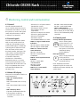
1
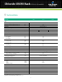
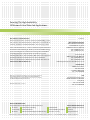
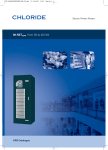
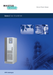
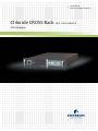
AC Power for
Business-Critical Continuity™
Chloride CROSS Rack 16 A, 32 A and 63 A
STS Catalogue
Chloride CROSS Rack STS 16 A, 32 A and 63 A
Chloride CROSS Rack
High Voltage and Low Voltage
2 Pole Complete Reliability On-line Static Switch
16 A, 32 A and 63 A
Scope 4
System Control
5
Protection Devices and Control Functions
6
Monitoring, Control and Communication
7
Installation Requirements 8
Technical Data 9
3
Chloride CROSS Rack STS 16 A, 32 A and 63 A
1 Scope
This specification describes the
Chloride CROSS Rack series of
single-phase, two-pole static
switches with manual maintenance
bypass switch, together with
information regarding the products'
electrical and mechanical features.
Chloride CROSS Rack is optimized
for installation in 19” standard rack
cabinets; the vertical rack space
occupation is 2 U for all models and
the protection degree is IP20 (i.e. no
openings are present on the top or
bottom of the Chloride CROSS Rack
enclosure). The air cooling is frontto-back and is obtained using fully
redundant monitored fans. All of
these features make Chloride CROSS
Rack the ideal solution for racklevel power protection in modern
data centers, ensuring maximum
reliability to critical loads by
eliminating system failures caused
by issues in distribution rather than
by the failure of the power source
itself.
1.1 The system
Chloride CROSS Rack ensures
redundant power to critical loads
through the ability to switch
between two alternative singlephase power sources. Switching will
occur whenever the line supplying
the load no longer falls within
the acceptable tolerance values.
Chloride CROSS Rack operates in
Fixed Priority Mode, in which the the
user selects the preferred input line,
allowing the Chloride CROSS Rack to
transfer to the priority line whenever
its parameters fall within acceptable
values.
Chloride CROSS Rack will function so
that the transfer between the two
sources will be break-before-make
(BBM) on both poles, thus ensuring
that the two sources will never be
directly connected.
Chloride CROSS Rack will ensure
switching between independent AC
power sources in both synchronous
and asynchronous conditions. When
the two lines are synchronous,
MODEL
Chloride CROSS Rack will transfer
between the sources within a
maximum of 6 ms following a line
failure. In asynchronous conditions
transfer will occur as described in
section 2.2.1. The acceptable phase
angle difference between the two
lines for asynchronous transfers will
be within a 15° range and selectable
by the user.
In order to maximize reliability,
Chloride CROSS Rack’s control logic
will be redundant and minimize
the use of common components.
Chloride CROSS Rack will rely on
front to back, forced and fully
redundant cooling.
1.2 Models available
Chloride CROSS Rack includes
models with single-phase input and
single-phase output, available in two
versions the High Voltage model
(HV) referring to a nominal voltage
of 230 V and the Low Voltage model
(LV) referring to a nominal voltage of
120 V, as specified below in Table 1.
Current (A)
Input
Output
Chloride CROSS Rack HV 16
16
Single-phase
Single-phase
Chloride CROSS Rack HV 32
32
Single-phase
Single-phase
Chloride CROSS Rack HV 63
63
Single-phase
Single-phase
Chloride CROSS Rack LV 16
16
Single-phase
Single-phase
Chloride CROSS Rack LV 32
32
Single-phase
Single-phase
Chloride CROSS Rack LV 63
63
Single-phase
Single-phase
Table 1. Chloride CROSS Rack Models
Nominal currents are intended as continuous and may apply to any type of linear and non linear
load (maximum crest factor 3:1)
4
Chloride CROSS Rack STS 16 A, 32 A and 63 A
2 System Control
The advanced control logic of
Chloride CROSS Rack provides the
highest safety for the load through
a break-before-make switching
in any mode of operation. All of
the power supplies and Silicon
Controlled Rectifier (SCR) firing
circuits are completely redundant.
The coloured LED on the front panel
of the Chloride CROSS Rack shall
provide a simple and immediate
indication of the operational state of
the system. For a more detailed and
complete description of diagnostics,
see section 4.2.
2.1 Mode of operation
The Chloride CROSS Rack will
attribute a priority to one of the
two sources. The priority source will
be selected from the front panel
by pressing push-button P. The
selected source will be indicated
by the corresponding LED (S1 or
S2). The selected priority source
will continuously supply the load
provided it remains within the
tolerance windows. Failure of
the priority source will initiate
transfer of the load to the reserve
(low priority) source. When the
priority line returns within the
acceptable tolerance window,
the load will automatically be
transferred back to the priority line
following a brief re-transfer time.
In the event of both sources falling
outside the acceptable tolerance
windows, Chloride CROSS Rack
can be programmed according to
the desired behavior (remain on
source1, remain on source2, open
both static switches).
2.2 Transfer modes
The Chloride CROSS Rack will
perform a break-before-make
switching under any condition.
Operating modes are described as
follows:
2.2.1 Line failure transfer
Switching occurs if the characteristic
parameters of the active power
source (preferred or alternative)
supplying the load fall outside
defined limits. The parameters
tested are the root mean square
(RMS) and instantaneous values
of the voltage, which must remain
within a defined acceptance
window. Once the parameters of
the power source have returned to
normal, if the load is supplied by the
source selected as the alternative,
it is automatically transferred back
to the priority source (see also
2.2.2). Where switching occurs
while sources are asynchronous,
it is possible to choose between
transferring in the shortest period
possible (6ms), as if the sources
were synchronous, or introducing an
additional delay (selectable between
0 and 20ms) to the normal transfer
time (default condition).
2.2.2 Transfer due to re-transfer of
load to priority source
In conditions where the priority
source is not the one supplying the
load (switching due to source fault
condition or change of priority via
push-button P), the Chloride CROSS
Rack will automatically transfer the
load to the priority source as soon
as possible. Specifically, automatic
switching to the priority source will
occur only when the parameters
of this last are within acceptable
limits and when synchronization is
established. If the priority source
is out of limits, transfer will be
effected only after it has remained
stable and within limits for a
5
preset period (5 seconds). In the
case of loss of synchronization,
transfer will only take place when
the phase difference between the
two sources is less than a preset
value (10° by default). In any event,
such switching occurs only when
both sources are within tolerance
and synchronized (transfer is also
effected during the zero current
crossing control in optimum
conditions). All settings and
operating modes of the Chloride
CROSS Rack can be easily modified
or enabled by trained customer
engineers.
2.3 Operation under output
short circuit
The Chloride CROSS Rack will inhibit
transfer whenever an output short
circuit is detected, thus avoiding
the transfer of the short circuit
to the alternative source. The
instantaneous short circuit threshold
level is 3In. Only when the current
falls below the threshold value and
the voltage value is acceptable,
does the Chloride CROSS Rack
automatically reset and enable
transfer.
The Chloride CROSS Rack’s internal
logic will inhibit transfers even if an
upstream protection device trips and
the current goes to zero.
2.4 Operation under
overload
The Chloride CROSS Rack will be able
to sustain the following overload
conditions:
125% 10
min.
150% 1
min.
700% 0.6
sec.
Chloride CROSS Rack STS 16 A, 32 A and 63 A
3 Protection Devices and Control Functions
2.5 Maintenance bypass and
Hot-Swap module
Devices to protect cables and loads must to be installed upstream and
The Chloride CROSS Rack is
equipped with bypass switches,
which allows complete maintenance
while ensuring continuous power to
the critical output load.
Both of the input sources can be
used during the maintenance bypass
operations. The switching devices
ensure that the direct connection
of the two sources is never possible,
even in the event of an error in user
operation.
The control logic will ensure that, in
the event of an accidental closure of
the bypass on the passive line, the
Chloride CROSS Rack will transfer
the load so as to avoid a permanent
paralleling of the two sources,
regardless of the operating modes
described above. Furthermore, to
ensure maintenance time is kept at
a minimum (optimized <1 minute
mean-time-to-repair with another
CROSS Rack available as spare),
the entire static module (logic and
solid state power devices) can be
extracted without interrupting the
supply (hot-swap maintenance) after
having switched the unit to manual
bypass as described above. Refer
to the User Manual for the detailed
description of the hot-swap module
maintenance.
or fuses and switches, selected in conformity with the Chloride CROSS Rack
downstream of the equipment. These devices can be automatic switches,
current rating, the overload performance, the internal fuses described in
section 3.1 and the downstream protections and loads.
3.1 Internal fuses
The Chloride CROSS Rack will be supplied with fuses on the input phase
of each source (660 Vac, 100 A; pre-arching I2T=2050 A2s, total I2T @
230 V = 3740 A2s). These fuses have the sole function of protecting the
subsystem and devices inside the unit itself from permanent output short
circuit. Downstream protection devices will therefore have to be correctly
dimensioned and coordinated.
3.2 Backfeed protection control
This feature prevents even the most remote possibility of electric shock
hazards on the alternative Chloride CROSS Rack mains supply terminal (the
source that is not currently supplying the load) in the event of a static switch
SCR failure (SCR shorted).
The user interface includes two normally-closed voltage-free contacts. These
are used to activate an external isolating device (electromechanical relays or
minimum voltage tripping relays can be used) when backfeed is detected. The
two external isolating devices are not included with the Chloride CROSS Rack
(in conformity with Standards), and must be 2 pole, air-gap isolator devices as
defined by IEC/EN 62310-1 (4.2.1.4).
3.3 Silicon Controlled Rectifier (SCR) open detector
The Chloride CROSS Rack will also be able to diagnose the fault condition
Open Circuit SCR on the active line. This fault condition will result in a transfer
to the passive line and inhibit further transfers.
3.4 Redundant cooling
The Chloride CROSS Rack is equipped with two fully redundant cooling fans.
This feature allows extremely reliable front-to-back ventilation. Each fan
is provided with a sensor which is able to detect the failure, which is then
immediately communicated to the user.
6
Chloride CROSS Rack STS 16 A, 32 A and 63 A
4 Monitoring, Control and Communication
4.1 General
The Chloride CROSS Rack will
incorporate the necessary controls,
instruments and indicators to allow
the operator to monitor the system
status and performance, as well as
to take appropriate action.
4.2 Control signals
The Chloride CROSS Rack is fitted
with a control panel on the front
of the unit. This includes a mimic
panel and LED lights to indicate the
operating status of the unit in realtime. The status of the sources,
the static switches, the bypass, the
load condition and the maximum
operating temperature are all
monitored continuously.
The functions of the LED are
described in section 4.3. On the
control panel a push-button is also
present which allows the user to set
the priority between the sources
and a LED which indicates the
current priority.
- If there is a loss of synchronization
between the sources
- If the Bypass switch is closed
- If the system is in Over temperature
- If there is an Output short circuit
- If there is a general SCR fault
- If there is a blocked fan
- If the EPO is active
- If the Backfeed Detector is active
• LED 6 & 7 - Bypass Switch Status
Indicators
LED ON = Bypass Switch CLOSED
LED OFF = Bypass Switch OPEN
• LED 8 & 9 - Source S1 and S2
Status Indicators
LED ON = Source OK
LED OFF = Source OUT OF
TOLERANCE
•LED 10 - Loss of Synchronization Indicator
LED ON = Sources NOT
SYNCHRONIZED
LED OFF = Sources
SYNCHRONIZED
• LED 11 & 12 - Static Switch
Status Indicator
4.3 Mimic LED display
The controls are located on the front
panel (see Figure 1).
•LED 1 & 2 - Priority Source
Indicator
LED 1 ON and LED 2 OFF = Priority
on S1
LED 1 OFF and LED 2 ON = Priority
on S2
•LED 4 Summary Alarm
This LED is illuminated under the
following alarm conditions:
- If at least one source is out of tolerance
S1
S2
Figure 1. A view of the display and control panel
7
LED ON = Static Switch CLOSED
LED OFF = Static Switch OPEN
•LED 13 - Output Alarm
LED13 ON = Switching Inhibited
due to Output short circuit and/or
Silicon Controlled Rectifier (SCR)
open fault
4.4 Control panel
Priority selection push-button
Press to select system
S1
S2 priority Source S1 or S2
Refer to section 2.1 for
more information about
the operation of Chloride
CROSS Rack during
Priority Selection
Reset push-button
Press to reset permanent
block (see Silicon
Controlled Rectifier (SCR)
Open Fault Alarm)
P
R
Note: The Reset command is
accepted only if both sources are
within the tolerances and they are
synchronized.
Chloride CROSS Rack STS 16 A, 32 A and 63 A
4.5 Output user signals
A summary alarm contact is
available as a cable screw terminal
connector, interfaced with a
voltage free relay contact (NO/NC
1A 220Vac). The summary alarm
is activated under the conditions
described in section 4.3. for LED 4.
Chloride CROSS Rack is also
equipped with a full set of digital
optically isolated output contacts.
These contacts can be accessed
from the rear panel of the unit on a
25-pin socket.
Digital Output list:
• Summary Alarm
• Priority on S1 / S2
• Output Short Circuit
• SCR-Open Fault
• System Over-temperature
• Bypass S1 Closed
• Bypass S2 Closed
• EPO Active
• S1 Out Of Tolerance
• S2 Out Of Tolerance
• Sources Synchronized
• S1 Static Switch Open/Closed
• S2 Static Switch Open/Closed
5 Installation Requirements
For detailed installation
requirements please refer to the
User Manual. No additional space is
required below or above the Chloride
CROSS Rack, and no openings are
present on the top or bottom of the
Chloride CROSS Rack enclosure.
8
• Backfeed detector active S1
• Backfeed detector active S2
• Fan failure
Digital outputs are optoisolated
signals (phototransistors); the
power supply has to be provided
externally (maximum current 3mA,
maximum DC voltage +15V).
4.6 Input user signals
Emergency power Off (EPO). When
the EPO is activated, all the static
switches are opened.
Chloride CROSS Rack STS 16 A, 32 A and 63 A
6 Technical Data
STS Unit
16 A
32 A
63 A
6.1
Nominal Voltage (selectable) - HV model
(V)
230 (220/240)
Nominal Voltage (selectable) - LV Model
(V)
120 (110/115)
Input voltage acceptance window (tolerance ±2)
(%)
±12
Input phases
Single phase (Ph + N)
Number of switching poles
2 (Ph + N)
Nominal frequency
(Hz)
Nominal Current
(A)
50/60 ±10%(1)
16
32
Input power ports
2
Output power ports
1
Efficiency at Nominal Power
(%)
≥99
Overload capacity
For 10 minutes
For 1 minute
For 0.6 seconds (%)
(%)
(%)
125
150
700
SCR Characteristics
I2T @ Tvj = 125°C
ITSM @ Tvj = 125°C
(A2s)
(A)
15000
1750
Fuses
Pre-arching I2T
Total I2T @ 230V
(A2s)
(A2s)
660 Vac, 100A fast
2050
3740
Temperature range
(°C)
0 - 40
Synchronization range
10° (5° - 15° selectable)
Cooling
Front to back, Forced, Fully redundant
Transfer Mode
Transfer Time
-Worst condition zero voltage source failure
-Typical zero voltage source failure
Break-Before-Make Switching (No source overlap)
(ms)
(ms)
CBEMA – ITIC compliant(2)
≤6
≤4
Additional transfer delay time for
non-synchronous transitions
(ms)
10 ±2 (0 - 20 selectable)
Re-transfer time
(s)
5
Instant Overcurrent Threshold
3 In
Dimensions
-Width
-Height
-Depth (w/o handles)
(mm)
(mm)
(mm)
Weight
(kg)
19"
2U
700 mm
23
Safety
CE marking, IEC/EN 62310-1
EMC Compatibility
Frame color
IEC/EN 62310-2
(RAL scale)
7016
Protection degree
Acoustic Noise
IP20
(dBA)
<45
MTTR (3)
<1 min
(1) At nominal voltage.
(2) For CBEMA-ITIC curve please consult www.itic.org
(3) In the case another CROSS Rack is available on site as spare.
9
63
Chloride CROSS Rack STS 16 A, 32 A and 63 A
Notes
10
Chloride CROSS Rack STS 16 A, 32 A and 63 A
Notes
Ensuring The High Availability
Of Mission-Critical Data And Applications.
Locations
About Emerson Network Power
Emerson Network Power, a business of Emerson (NYSE:EMR), protects
Emerson Network Power
Via Leonardo Da Vinci 16/18
Zona Industriale Tognana
35028 Piove di Sacco (PD) Italy
Tel: +39 049 9719 111
Fax: +39 049 5841 257
and optimizes critical infrastructure for data centers, communications
networks, healthcare and industrial facilities. The company provides
new-to-the-world solutions, as well as established expertise and smart
innovation in areas including AC and DC power and renewable energy,
precision cooling systems, infrastructure management, embedded
computing and power, integrated racks and enclosures, power
switching and controls, and connectivity. Our solutions are supported
globally by local Emerson Network Power service technicians.
Learn more about Emerson Network Power products and services at
www.EmersonNetworkPower.eu
Via Fornace, 30
40023 Castel Guelfo (BO) Italy
Tel: +39 0542 632 111
Fax: +39 0542 632 120
[email protected]
United States
1050 Dearborn Drive
P.O. Box 29186
Columbus, OH 43229
Tel: +1 614 8880246
Asia
7/F, Dah Sing Financial Centre
108 Gloucester Road, Wanchai
Hong Kong
Tel: +852 2572220
Fax: +852 28029250
While every precaution has been taken to ensure accuracy and completeness
herein, Emerson assumes no responsibility, and disclaims all liability, for
damages resulting from use of this information or for any errors or omissions.
Specifications subject to change without notice.
MKA4CAT0UKCROSR Rev. 1-02/2013
Emerson Network Power
The global leader in enabling Business-Critical Continuity™.
EmersonNetworkPower.eu
AC Power
Embedded Computing
Outside Plant
Racks & Integrated Cabinets
Connectivity
Embedded Power
Infrastructure Management & Monitoring
Power Switching & Controls
Services
Precision Cooling
Surge Protection
DC Power
Emerson, Business-Critical Continuity and Emerson Network Power are trademarks of Emerson Electric Co. or one of its affiliated companies. ©2013 Emerson Electric Co.