1
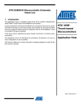
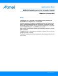
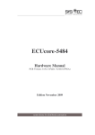
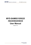
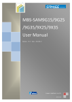
Glomation
Embedded CPU Module
GECM-9G25
User’s Manual
GECM-9G25/35 User’s Manual
Table of Contents
Chapter 1 – Introducing the GECM-9G25 CPU Module .................................................................. 4 GECM-9G25 Overview ................................................................................................................. 4 Advanced Features ......................................................................................................................... 4 Chapter 2 – GECM-9G25 Function Blocks ....................................................................................... 6 AT91SAM9G25............................................................................................................................. 6 DDR2 RAM ................................................................................................................................... 7 FLASH ........................................................................................................................................... 7 Clock Circuitry............................................................................................................................... 7 Reset Circuitry ............................................................................................................................... 8 Power Supply ................................................................................................................................. 8 SODIMM 200 Interface ................................................................................................................. 9 Connector ..................................................................................................................................... 11 Chapter 3 – Software Description .................................................................................................... 13 Overview ...................................................................................................................................... 13 Data Storage on GECM-9G25 ..................................................................................................... 13 GECM-9G25 Linux Code ............................................................................................................ 13 U-boot .......................................................................................................................................... 13 U-Boot Booting Linux ................................................................................................................. 13 Loading Linux Kernel and root File System................................................................................ 14 Chapter 4 – Development Tools ...................................................................................................... 17 Version 0.2
Page 2 of 17
27-Feb-14
GECM-9G25/35 User’s Manual
List of Tables
Table 1 Power Sources...................................................................................................................... 8 Table 2 J1 SODIMM 200 Card Edge Connector .............................................................................. 9 Table 3 NAND FLASH Storage Map .............................................................................................. 13 Version 0.2
Page 3 of 17
27-Feb-14
GECM-9G25/35 User’s Manual
Chapter 1 – Introducing the GECM-9G25 CPU Module
GECM-9G25 Overview
The GECM-9G25 is a low cost compact sized CPU Module based on Atmel AT91SAM9G25
processor. It integrates all the core components and is mounted onto an application-specific carrier
board using the standard SODIMM form factor. This approach allows the customer to design a
customer carrier board, that meets the customer's I/O, dimensional, and connector requirements
without having to go through complicated design process of the processor, memory, and standard
I/O functionality. This approach can significantly reduce the development time and simplifying
the process of developing a complete customer product. With a large peripheral set targeted to a
variety of applications, the GECM-9G25 is well suited for industrial controls, digital media servers,
audio jukeboxes, thin clients, set-top boxes, point-of-sale terminals, biometric security systems,
and GPS devices.
Figure 1. GECM-9G25 CPU Module
Advanced Features
The heart of the GECM-9G25 is the AT91SAM9G25 which is the one in a series of ARM926EJS-based processors. The AT91SAM9G25 microcontroller features DSP Instruction Extensions,
ARM Jazelle® Technology for Java® Acceleration. It has separate 32 Kbyte instruction and data
caches with write buffer. The ARM926EJ-S on the AT91SAM9G25 functions with a maximum
operating clock rate of 400MHz and a power usage between 20mW and 80mW (dependent upon
clock speed). The ARM core operates from a 1V supply while the I/O operates at 3.3V. The low
power consumption makes it an idea platform for battery operated applications.
Version 0.2
Page 4 of 17
27-Feb-14
GECM-9G25/35 User’s Manual
The list below summarizes the features of the GECM-9G25.
•
•
•
•
•
•
•
•
•
•
•
•
•
•
400MHz Processor Core – ARM926EJ-S with MMU
128 MB DDR2RAM
256MB ~ 1GB NAND FLASH
1 10/100 Mbps Ethernet MAC
12 channel 10-bit Analog-to-Digital Converter (ADC
4 Universal Asynchronous Receiver / Transmitters (UARTs)
2 USB Host Port
1 USB Device Port
Real-Time Clock
Watchdog Timer
Hardware Debug Interface
SD/MMC Socket
I2C Port
SPI Port
Version 0.2
Page 5 of 17
27-Feb-14
GECM-9G25/35 User’s Manual
Chapter 2 – GECM-9G25 Function Blocks
The GECM-9G25 is designed as the heart of the system. It connects to the application specific
carrier board through the SODIMM 200 interface. It consists of the processor and external
memory and the board itself servers as a minimal CPU sub-system. The signals of a full suite of
peripheral functions, such as USB, SD/MMC, I2C, I2S, Ethernet, etc, are routed to the SODIMM
connector to be passed to the application specific carrier board. The following diagram shows the
board architecture.
Figure 1. GECM-9G25 Block Diagram
AT91SAM9G25
The GECM-9G25 CPU Module uses the Atmel AT91SAM9G25 as the core processor on the
computer module. The top-level features of AT91SAM9G25 processor are the following:
•
ARM926EJ-S RISC Core Processor
•
400 MHz / 400 MIPS Performance
•
16Kbyte Instruction Cache
Version 0.2
Page 6 of 17
27-Feb-14
GECM-9G25/35 User’s Manual
•
16Kbyte Data Cache
•
Linux and Windows CE enabled MMU
•
133 MHz System Bus
•
32 bit External Bus Interface Supporting 8-banks DDR2/LPDDR, SDR/LPSDR, Static
Memory
•
MLC/SLC NAND Controller, with up to 24bit Programmable Multi-bit Error Correcting
Code (PMECC)
•
Serial EEPROM Interface
•
10 / 100 Mbps Ethernet MAC
•
USB High Speed Host Port, USB Full Speed Host Port, USB High Speed Device Port
•
Two High Speed Memory Card Hosts
•
4 UART
•
Two-port USB Host (High Speed & Full Speed)
•
12 channel 10 bit ADC
•
2 Master/Slave SPI Port
•
Serial Audio Interface
•
JTAG Interface
More detailed information regarding the AT91SAM9G25 processor can be found at
www.atmel.com.
DDR2 RAM
The GECM-9G25 is equipped with 128MByte of DDR2RAM (double data rate synchronous
dynamic memory). With the system clock running at 133MHz it can achieve a maximum transfer
rate of ~ 1066 MB/S.
FLASH
The GECM-9G25 is shipped with 256 Mbytes of NAND FLASH memory. The GECM-9G25 can
be also ordered with optional 512MB ~ 1GB NAND FLASH.
Clock Circuitry
The GECM-9G25 CPU Module includes tow clock sources, 32.768KHz crystal for RTC and
12MHz crystal for main system clock.
Version 0.2
Page 7 of 17
27-Feb-14
GECM-9G25/35 User’s Manual
Reset Circuitry
The reset sources for the GECM-9G25 are,
•
•
•
Power on reset
Push button reset (from carrier board)
JTAG reset from an in-circuit emulator (option JTAG interface on carrier board)
Power Supply
The GECM-9G25 CPU Module contains its own power supply generation circuit to generate
necessary power source for the processor and main memory. Additional power source for other
peripheral functions should be provided by carrier board to the CPU module through the SODIMM
interface. The following table lists the power source and functionality.
Table 1 Power Sources
Nominal
Name
3.3V
VDDNF
3.3V
3.3V
3.0V
3.3V
3.3V
3.3V
1.8V
1.0V
3.3V
1.0V
1.0V
3.0V/3.3V
Version 0.2
Powers
NAND Flash and D16 ~ D32
Multiplex SMC Data Lines
VDDIOP0
VDDIOP1
VDDBU
Partial Peripheral I/O lines
Partial Peripheral I/O lines
The Slow Clock Oscillator,
the 32KHz RC, the Internal
12MHz RC and Part of the
System Controller
VDDUTMII
The USB Device and Host
UTMII+ Interface
VDDOSC
The Main Oscillator Cell
VDDANA
The Analog to Digital
Converter
VDDIOM
The External Memory
Interface
VDDUTMIC
DC Supply UDPHS and
UHPHS UTMI+ Core
VDDPLLUTMI DC Supply UDPHS and
UHPHS UTMI interface
VDDPLLA
The PLLA Cell
VDDCORE
CPU Core Power Supply
ADVREF
ADC Reference voltage
Page 8 of 17
Source
Derived from 3.3V From
SODIMM connector.
Output to the SODIMM as
VDDNF for carrier board
voltage shifter (if needed).
From SODIMM connector
From SODIMM connector
From SODIMM connector
From SODIMM connector
From SODIMM connector
From SODIMM connector
On-board Power Supply
On-board Power Supply
From SODIMM connector
From SODIMM connector
On-board Power Supply
From SODIMM connector
27-Feb-14
GECM-9G25/35 User’s Manual
SODIMM 200 Interface
The GECM-9G25 CPU Module uses SODIMM card edge connector to interface the application
specific carrier board. The pin out of the SODIMM connector is listed in the following table.
Table 2 J1 SODIMM 200 Card Edge Connector
Function
Type x5 pad and name SODIMM 200
Front Side
A
B
VCC 3V3
VCC 3V3
GND
USBC_DP
USBC_DM
GND
USBB_DM
USBB_DP
GND
DIBP
DIBN
GBN
USBA_DM
USBA_DP
GND
RFU
RFU
RFU
RFU
RFU
GND
RFU
RFU
RFU
RFU
GND
RFU
RFU
RFU
RFU
VDDNF
PD0
PD2
PD4
PD6
PD8
GND
PD10
PD12
PD14
PD16
PD18
PD20
VDDIOP0
Version 0.2
Power Input
Power Input
I/O
I/O
USB Data Positive
USB Data Negative
I/O
I/O
USB Data Negative
USB Data Positive
I/O
I/O
I/O
I/O
USB Data Negative
USB Data Positive
RFU
RFU
RFU
RFU
RFU
RFU
RFU
RFU
RFU
RFU
RFU
RFU
RFU
NAND FLASH Power Domain
GPIO D NANDOE
GPIO D A21/NANDALE
GPIO D NCS3
GPIO D D16
GPIO D D18
GPIO D D20
GPIO D D22
GPIO D D24
GPIO D D26/A23
GPIO D D28/A25
GPIO D D30/NCS4
POWER INPUT
1
3
5
7
9
11
13
15
17
19
21
23
25
27
29
31
33
35
37
39
41
43
45
47
49
51
53
55
57
59
61
63
65
67
69
71
73
75
77
79
81
83
85
87
Page 9 of 17
2
4
6
8
10
12
14
16
18
20
22
24
26
28
30
32
34
36
38
40
42
44
46
48
50
52
54
56
58
60
62
64
66
68
70
72
74
76
78
80
82
84
86
88
x5 pad and name
Type
Back Side
Power Input
Power Input
Power Input
VCC 3V3
VCC 3V3
VBAT
SYSC
SYSC
SYSC
SYSC
SYSC
SYSC
RSTJTAG
RSTJTAG
RSTJTAG
RSTJTAG
RSTJTAG
Power Enable Input
RFU
RFU
RFU
RFU
RFU
RFU
RFU
RFU
RFU
RFU
RFU
RFU
RFU
NAND FLASH Power Domain
NANDWE
GPIO D
A22/NANDCLE
GPIO D
NWAIT
GPIO D
D17
GPIO D
D19
GPIO D
D21
D23
D25/A20
D27/A24
D29/NCS2
D31/NCS5
POWER INPUT
Function
GPIO D
GPIO D
GPIO D
GPIO D
GPIO D
GPIO D
JTAGSEL
WKUP
SHDN
BMS
NRST
NTRST
TDI
TCK
TMS
TDO
RTCK
PWR_EN
RFU
RFU
RFU
RFU
RFU
GND
RFU
RFU
RFU
RFU
GND
RFU
RFU
RFU
RFU
VDDNF
PD1
PD3
PD5
PD7
PD9
GND
PD11
PD13
PD15
PD17
PD19
PD21
VDDIOP0
27-Feb-14
GECM-9G25/35 User’s Manual
PA0
PA2
GPIO A
GPIO A
PA4
GPIO A
PA11
GPIO A
PA13
GPIO A
GND
PA8
PA22
PA31
GPIO A
GPIO A
GPIO A
RCD2/SPI1_NPCS0
TIOA1/SPI1_MOS1
TWCK0/SPI1_NPC
S2/E0_ETXEN
GPIO A
GPIO A
GPIO A
GPIO A
GPIO A
MCI0_CDA
MCI0_DA1
MCI0_DA3
TXD1/CANTX1
DTXD/CANTX0
GND
PA16
PA18
PA20
PA5
PA10
GND
PA25
PA27
PA29
VDDOIP1
PC0
PC2
PC4
GND
PC7
PC9
PC11
PC12
PC14
GND
PC17
PC19
PC21
PC22
PC24
PC26
GND
PC29
PC31
VDDANA
PB0
PB2
PB4
PB6
PB8
PB9
PB11
PB13
Version 0.2
TXD0/SPI1-NPCS1
MCI1_DA1/E0_ET
X0
SCK0/MCI1_DA3/
E0_ETXER
SPI0_MISO/MCI1_
DA0
SPI0_SPCK/MCI1_
CK
GPIO A TCLK1/TF
GPIO A TIOB0/RD
GPIO A TIOB2/RF
POWER INPUT
GPIO C LCDDAT0/ISI_D0
GPIO C LCDDAT2/ISI_D2
GPIO C LCDDAT4
GPIO C
GPIO C
GPIO C
GPIO C
GPIO C
LCDDAT7
LCDDAT9
LCDDAT11
LCDDAT12
LCDDAT14
GPIO C
GPIO C
GPIO C
GPIO C
GPIO C
GPIO C
LCDDAT17
LCDDAY19
LCDDAT21
LCDDAT22
LCDDSIP
LCDPWM
GPIO C LCDDEN
GPIO C E1_MDIO
POWER INPUT
GPIO B E0_RX0
GPIO B E0_RXER
GPIO B E0_TXCK
GPIO B E0_MDC
GPIO B E0_TXER
GPIO B E0_TX0
GPIO B E0_TX2
GPIO B E0_RX2
89
91
90
92
93
94
95
96
97
98
99
101
103
105
100
102
104
106
107
109
111
113
115
117
119
121
123
125
127
129
131
133
135
137
139
141
143
145
147
149
151
153
155
157
159
161
163
165
167
169
171
173
175
177
179
181
183
108
110
112
114
116
118
120
122
124
126
128
130
132
134
136
138
140
142
144
146
148
150
152
154
156
158
160
162
164
166
168
170
172
174
176
178
180
182
184
Page 10 of 17
RXD0/SPI0-NPCS2
CTS0/MCI1_DA2/E
0_ETX1
GPIO A
GPIO A
PA1
PA3
GND
SPI0_MOSI/MCI1_
CDA
SPI0_NPCS0
GPIO A
PA12
GPIO A
PA14
TXD2/SPI0_NPCS1
TIOA0/SPI1_MISO
TIOA2/SPI1_SPCK
TWD0/SPI1_NPCS3
/E0_EMDC
MCI0_DA0
MCI0_CK
MCI0_DA2
GPIOA
GPIO A
GPIO A
GPIO A
PA7
PA21
PA23
PA30
GPIO A
GPIO A
GPIO A
RXD1/CANRX1
DRXD/CANRX0
TCLK0/TK
TCLK2/TD
TIOB1/RK
GPIO A
GPIO A
GPIO A
GPIO A
GPIO A
POWER INPUT
LCDDAT1
LCDDAT3
LCDDAT5
LCDDAT6
LCDDAT8
LCDDAT10
GPIO C
GPIO C
GPIO C
GPIO C
GPIO C
GPIO C
LCDDAT13
LCDDAT15
LCDDAT16
LCDDAT18
LCDDAT20
GPIO C
GPIO C
GPIO C
GPIO C
GPIO C
LCDDAT23
GPIO C
GPIO C
GPIO C
GPIO C
GPIO C
GPIO B
GPIO B
GPIO B
GPIO B
PA15
PA17
PA19
GND
PA6
PA9
PA24
PA26
PA28
GND
VDDIOP1
PC1
PC3
PC5
PC6
PC8
PC10
GND
PC13
PC15
PC16
PC18
PC20
GND
PC23
PC25
PC27
PC28
PC30
SELCONFIG
VDDANA
PB1
PB3
PB5
PB7
GPIO B
GPIO B
GPIO B
PB10
PB12
PB14
LCDVSYNC
LCDHSYNC
E1_MDC
POWER INPUT
E0_RX1
E0_RXDV
E0_MDIO
E0_TXEN
GNDANA
E0_TX1
E0_TX3
E0_RX3
27-Feb-14
GECM-9G25/35 User’s Manual
PB15
PB17
PB18
GND
ETH0_TX+
ETH0_TXETH0_RX+
ETH0_RX-
GPIO B
GPIO B
GPIO B
E0_RXCK
E0_COL
IRQ
185
187
189
191
193
195
197
199
186
188
190
192
194
196
198
200
E0_CRS
GPIO B
GNDANA
A/D Voltage Reference
PB16
POWR_REF
LED0
LED1
LED2
AVDDT
GND_ETH
Please note the PD0 ~ PD13 are used by the GECM-9G25/35 module for on-board NAND FLASH.
The on-board NAND FLASH can be disabled by disconnecting the NAND CE signal so the
NAND control signals can be used on the carrier board. The PB18 and PD21 are used by the
GECM-9G25/35 for the on-board LED. They can be reclaimed by removing the LEDs on the
GECM-9G25/35 board.
Connector
The GECM-9G25 CPU Module uses SODIMM card edge connector to interface the carrier board.
The board dimensions is shown below.
Version 0.2
Page 11 of 17
27-Feb-14
GECM-9G25/35 User’s Manual
Figure 1. SODIMM 200 Dimensions
Version 0.2
Page 12 of 17
27-Feb-14
GECM-9G25/35 User’s Manual
Chapter 3 – Software Description
Overview
This chapter provides information regarding the software that is shipped with the GECM-9G25
Board. The software included with the board is U-Boot boot loader, Linux kernel 2.6.39, and an
embedded root file system.
Data Storage on GECM-9G25
The default configuration of the GECM-9G25 CPU Module uses on board NAND FLASH for all
data storage requirements, including boot strap code, boot loader, Linux kernel, and Linux file
system.
The following table is the factory default storage map on the NAND FLASH.
Table 3 NAND FLASH Storage Map
Start Address
Size
0x00000000
0x20000
0x00040000
0x40000
0x000C0000
0x20000
0x000E0000
0x20000
0x00200000
0x300000
0x00800000
--
Usage
Boot strap code
U-Boot
U-Boot primary environment storage range
U-Boot secondary environment storage range
Linux kernel
Root file system
GECM-9G25 Linux Code
The GECM-9G25 is shipped with Linux 2.6.39 kernel pre-installed. This software is programmed
into the system FLASH located on the board prior to shipment. The Linux kernel is configured
with most of the device drivers included for the GECM-9G25 board.
U-boot
U-Boot provides a simple interface for loading operating systems and applications onto the
GECM-9G25 board. U-Boot uses a serial console for its input and output. The default serial port
setting is 115200,8,N,1. It also supports the built-in Ethernet port and general flash programming.
The board is shipped with U-Boot pre-installed. Please refer to U-Boot user’s manual regarding
detailed information of U-Boot.
U-Boot Booting Linux
The following shows the default U-Boot setup for booting Linux.
Version 0.2
Page 13 of 17
27-Feb-14
GECM-9G25/35 User’s Manual
U-Boot> printenv
bootargs=mem=128M console=ttyS0,115200 mtdparts=atmel_nand
8M(bootstrap/uboot/kernel)ro,-(rootfs) root=/dev/mtdblock1 rw
rootfstype=ubifs ubi.mtd=1 root=ubi0:rootfs
bootdelay=1
baudrate=115200
ethaddr=00:0c:20:02:0a:5b
ipaddr=192.168.0.200
serverip=192.168.0.102
netmask=255.255.255.0
stdin=serial
stdout=serial
stderr=serial
ethact=macb0
Environment size: 353/131067 bytes
U-Boot>
The bootcmd setting of the U-Boot reads the Linux kernel from NAND FLASH at address
0x200000 to SDRAM at address 0x22000000 and start executing the kernel code at the same
memory address. The NAND FLASH from 0x800000 and up is used for Linux root file system.
The U-Boot passes the MTD device partition setting to the Linux kernel via the bootargs
environment variable.
Loading Linux Kernel and root File System
The U-Boot boot-loader provides many ways to load Linux kernel and file system into FLASH
memory. The loading by Ethernet network is shown here. User can consult U-Boot manual for
other methods of loading data.
After power on the GECM-9G25 board, stop the U-boot auto-execution by press any key. The
following message should be shown on the terminal console on the host PC connected to the
GECM-9G25 board.
Version 0.2
Page 14 of 17
27-Feb-14
GECM-9G25/35 User’s Manual
RomBOOT
Start AT91Bootstrap...
Init DDR... ba_offset = 0xb ... Done!
Loading 1-Wire info...
Enumerate all roms:
Rom#0x0: 0xa3 0x0 0x0 0x3 0x21 0x88 0x63 0x2d
Done, 0x1 1-wire chips found!
Board name: SAM9x5-EK [B0]; Vendor name: FLEX
sn: 0x4000023;
rev: 0x8401
Downloading image...
chip id: 0xecda
Copy 0x50000 bytes from 0x40000 to 0x26f00000
Done!
U-Boot 2010.06 (Jun 23 2011 - 16:05:54)
DRAM:
NAND:
128 MiB
256 MiB
The network address and server address must be set before network transfer can take place. The
following commands will set the SBC IP address and server IP address,
set ipaddr xxx.xxx.xxx.xxx
set serverip xxx.xxx.xxx.xxx
The server IP is the IP address where a TFTP server must be run. To load Linux kernel type in the
following command,
tftp 0x22000000 uImage
The U-Boot will load uImage file from the TFTP server whose IP address is specified by the
serverip environment variable.
The NAND FLASH sectors must be erased first before new kernel image can be stored. The
following command will erase the NAND FLASH sectors reserved for Linux kernel,
nand erase 0x200000 0x200000
The use the flowing command to store the kernel image from SDRAM to NAND FLASH,
nand write.jffs2 0x22000000 0x200000 0x200000
The following commands can be used to load root file system into the FLASH memory,
nand erase 0x800000 [available_nand_flash_memory_size]
tftp 0x21000000 rootfs.img
nand write.jffs2 0x21000000 0x800000 $(filesize)
Version 0.2
Page 15 of 17
27-Feb-14
GECM-9G25/35 User’s Manual
Please be noted that the image is first loaded into the SDRAM and then stored into the FLASH
memory. The image size can not exceed the available SDRAM on the board.
After the kernel and root file system have been updated the board can be simply reboot by recycle
the power.
Version 0.2
Page 16 of 17
27-Feb-14
GECM-9G25/35 User’s Manual
Chapter 4 – Development Tools
Glomation provides a pre-configured VMWare image based Linux Debian distribution that
includes cross development tool chain, Eclipse IDE, sample project and sample program. The user
and password pairs for the VMWare image are root:root and user:user. The VMWare image is
available in the support page at Glomation website, http://www.glomationinc.com/support.html
Version 0.2
Page 17 of 17
27-Feb-14