1
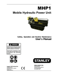
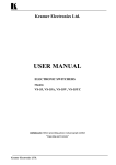
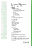
Item# 109089
24-Gallon Air-Operated Oil Drainer
User’s Manual
Assembly and Operation Instructions
MADE IN CHINA
For technical questions and replacement parts, please call 1-800-556-7885.
Thank you very much for choosing a NORTHERN TOOL & EQUIPMENT CO., Product! For
future reference, please complete the owner’s record below:
Model: _______________
Purchase Date: _______________
Save the receipt, warranty and these instructions. It is important that you read the entire
instruction sheet to become familiar with this product before you begin using it.
This machine is designed for certain applications only. Northern Tool & Equipment strongly
recommends that this machine is not modified and/or used for any application other than that
for which it was designed. If you have any questions relative to a particular application, DO NOT
use the machine until you have first contacted Northern Tool & Equipment to determine if it can
or should be performed on the product.
Before using this product, please read the following instructions carefully.
WARNING!
Do not extract caustic or flammable products. Do not expose the reservoir to any source of
heat. While extracting high temperature oils, keep hands and face protected. Only use the
device for the purpose for which it has been designed. Do not modify any component of the
equipment. Only use original spare parts. Our technical office is at your full disposal for any
information you may need.
ASSEMBLY
Fig.1:
Insert the handle B into its seat and secure it with the screws provided.
position the tool tray A.
Fig.2:
Attach ball valve C to the drain basin and tighten it with a suitable wrench.
Fig.3: Connect the assembled group the reservoir tank by tightening ring nut D using a
suitable wrench and screw with handwheel E.
Fig.4: Attach the hose with the ball valve and adapter F on the base of the units tank.
1
OPERATION
Fig.5:To raise and lower the catch basin, loosen handwheel E by turning it counter clockwise;
tighten with handwheel E by turning it clockwise after reaching desired height.
CAUTION
Never fill the reservoir over the maximum level indicated by the gauge that is located on the
side of the reservoir.
EMPTYING
IMPPORTAN!!
Fig.6.
Make sure that valve C is closed . Make sure that screw E is tightened.
Attach the end of the drain hose to a suitable waste oil container.
Open ball valve G.
Connect compressed air (7PSI) to quick couple M and open the ball valve H. After the fluids
have been transferred from the unit’s reservoir tank close ball valve G.
The unit is equipped with a safety valve that has been factory calibrated at 14PSI.
2
Parts List
No.
Description
Quantity
No.
Description
Quantity
No.
Description
Quantity
1
SPRING LOCK WASHER
2
13
CHAIN
1
25
TOOL TRAY
1
2
WHEELS
2
14
PAN HEAD SCREW
1
26
O-RING 26.5X3.55
2
3
RESERVOIR 90L
1
15
STUFF
1
27
O-RING 42.5X2.65
1
4
SWIVELLING WHEELS
2
16
O-RING 16X2.4
2
28
HANDWHEEL
1
5
PLAIN WASHER
2
17
SCREW WITH CHAMFERED END
2
29
SEAT
1
6
ACORN NUT
2
18
SCREW
1
30
ROUND NUT WITH COLLAR
1
7
ELBOW
2
19
SET OF SCREWS FOR RESERVOIR
1
31
ADJUSTING STEEL TUBE
1
8
RING
2
20
HANDLE
1
32
BALL VALVE
1
9
TUBE WITH LABEL
1
21
PLUGS
1
33
OIL COLLECTING BOWL
1
10
DOUBLE END ADAPTER
1
22
O-RING 10X1.8
1
34
FILTRATING PLANK
1
11
BALL VALVE
1
23
Y-ELBOW ADAPTER
1
35
SPRING
1
12
DISCHARGING HOSE
1
24
SAFETY VALVE
1
36
NUT
1
3