1
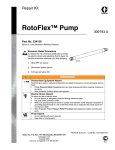
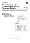
GENUINE GRACO PARTS AND ACCESSORIES
563933 MSP Bubble Tight
Inlet Shut-Off Valve Repair Kit
Important Safety Instructions
Read all warnings and instructions in manual. Save
these instructions.
406684B
Included in Kit 1
Ref. Description
Qty.
1
KIT, solenoid
1
2
SEAT, nylon
1
3
NUT, wrench (not shown)
1
4
SCREW, 1 1/4-6 flat head (not
shown)
1
2
Nylon seat (2) face down
ti10990a
Graco Inc. P.O. Box 1441 Minneapolis, MN 55440-1441
406684 Rev, B 06/2009
Copyright 2007, Graco Inc. is registered to ISO 9001
Repair Instructions
Disassembly
Reassembly
1. Remove the 1/2-20 acorn nut at the top of the
solenoid coil and pull the coil off.
1. Place a new nylon seat (2) with its chamfered hole
downward over the nylon seat-well with its axis as
vertical as possible.
2. Slip the spanner nut (3, not shown) over rod.
Insert into the two holes in the retaining disc.
Loosen with a wrench.
3. Carefully remove the poppet valve components
including the metal poppet guide disc below and
inside the o-ring to expose the nylon valve seat.
Put aside all parts in order of their removal and
with a proper orientation to each other to serve as
a guide for reassembly of parts removed.
4. Insert a 1-1/4 x 6 (4, not shown) all purpose screw
into the end of a slide hammer (user provided) or
similar device. Place the screw tip into the small
hole in the center of the nylon seat and turn it
approximately two turns into the seat.
CAUTION: The nylon seat is only 0.150 inch deep.
Do not turn the screw in more than 1/8
inch in order to avoid damage to the valve
body below the nylon seat.
5. Apply the slide-hammer action several times until
the nylon seat is pulled completely free of the
seat-well. Remove the used nylon seat and
discard.
2. Place the metal poppet-guide disc on top of the
nylon seat and then a 0.600-0.660 inch O.D. metal
cylinder (e.g., a 1/4 inch drive ratchet-wrench,
7/16 inch socket) on top of the disc. Tap the metal
cylinder with a nylon hammer until the nylon seat
is fully inserted into the well. Remove the metalpoppet guide disc to verify.
3. Reinstall the metal poppet-guide disc and the new
valve components provided in the solenoid kit (1).
Use the disassembly orientation from Step 3 as a
reference. Discard used components when
complete.
4. Tighten the poppet valve’s retaining disc with the
spanner nut (3) to 8-10 ft-lbs torque. Remove
spanner nut.
5. Reinstall solenoid coil onto the valve rod and
secure with the acorn nut tightened to 30-55 in-lbs
torque.