1
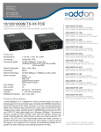
FBrief introduction
Many thanks for purchasing PoE (PSE) Media
Converter! This product supports IEEE802.3U
IEEE802.3z
1000Base-Tx/Fx
protocol
and
IEEE802.3af PoE PSE application, internal AC/DC
power supply and PSE controller can output up to
25Watts
(DC48V/540mA,)
or
15.4Watts
(DC48V/350mA,) power into CAT5 twisted-pair cable.
The following purchasing guide is for customer’s
reference.
FPacking list
Please check the following items in the package
before installing the media converter.
PoE (PSE) media converter
1set
AC Power cable
1pc
User manual
1copy
Please contact the dealer immediately for any loss or
damage to the above items.
of media converter through the attached AC power
cable.
2. Connection
The network device (network card, hub or switch, etc)
with RJ-45 interface is connected to RJ-45 jack of
media converter through twisted-pair. And the
multi/single mode optical fiber is connected to SC/ST
fiber interface of the optical transceiver module.
Then connect the AC power cables, the media
converter will work. The corresponding LED is on for
correct connection. (See the table below for the LED
indicator lamp)
ON 100M
100M
OFF 1000M (1000M ON) or 10M (1000M OFF)
ON when connect a correct PD load
POE
OFF when no load or wrong load
Blinking when load is abnormal
ON when POE 48V power is ok
PWR/POE
OFF when P
OE 48V power is losing or too low
F Introduction to dip switches
NO.
Function
SW1-1
ENROM *
SW1-2
Specification
OFF
Disable
ON
Enable EEPROM SET
OFF
FX 1000M (default)
ON
FX 100M
FX100M *
OFF
SW1-3
NULL
Reserved
ON
FInstallation
1. Interface
RJ-45 interface
The transmission media adopts CAT5 twisted-pair
with maximum length up to 100meters (330feets).
Fiber interface
SC/ST fiber interface is of duplex mode type,
including two interfaces, namely TX and RX. When
the two sets of optical transceiver are interfaced or
connected to switch with fiber interface, the fiber is in
cross connection, namely "TX-RX", "RX-TX" (direct
butting for single optical fiber transceiver module).
Power supply interface
The AC power supply is connected to AC-input jack
Status
FDescription for LED indicator lamp
PWR
Disable
LFP *
ON
Enable
OFF/OFF
Store and Forward mode
OFF/ON
Modified cut through mode
ON/OFF
Smart pass through mode
ON/ON
Pass through mode
ON when the power supply is turned on
Bright when optic fiber cable is connected well, but no
Link/Act
OFF
SW1-4
SW1-5
MODE1 **
data transmission
(FX)
Blinking when receiving data
Bright when twisted pair is connected well, but no data
Link/Act
transmission
(TP)
Blinking when receiving data
ON when TP link is in full duplex mode
FDX(TP)
OFF when TP link is in half duplex mode
ON 1000M
1000M
OFF 100M or 10M
SW1-6
MODE0 **
Note:
l *SW1-2(FX100M) / SW1-4(LFP) will be active
only when SW1-1(ENROM) is ON;
l **SW1-5(MODE1) and SW1-6(MODE0) are
combined keys to select switch forward mode
(MODE1/MODE0).
FMain features
1. In conformity to IEEE802.3U IEEE802.3z
1000Base-Tx/Fx standard.
2. IEEE802.3af PoE PSE compatible
3. Half duplex: back pressure flow control
Full duplex: IEEE802.3x flow control.
4. Automatic identification of MDI/MDI-X cross line..
5. Supports link fault pass through function.
FTechnical parameters
1. Standard Protocol: IEEE 802.3u 100 Base-TX,
IEEE802.3z, IEEE802.3ab standard, IEEE802.3af
2. Connector:
one UTP RJ-45 connector, one
SC/ST connector, one AC-inlet connector
3. Operation mode: full duplex mode or half duplex
mode
4. Power supply parameter: 100-240V AC
5. Environmental temperature: 0℃ -50 ℃
6. Relative humidity: 5%-90%
8. TP cable: Cat5 UTP cable
9. Optical fiber:
multi-mode: 50/125, 62.5/125 or 100/140μ m
single mode:: 8.3/125, 8.7/125, 9/125
10 Dimensions:
Power internal:
140mm(L) x 110mm(W)x40mm(H)
FCautions:
1. This product is suitable for indoor application.
2. Put on the dust cover of fiber interface when not
used.
3. It is forbidden to stare at the TX fiber-transfer end
with naked eyes.
4. Single optical fiber transceiver must be used in
pair
FTrouble shooting
1. Device is not matched. Please select the
corresponding network device according to the
transfer rate of the product (10Mbps, 100Mbps or
1000Mbps) when connected to other network
devices (network card, hub, switch, etc).
2. Line loss is excessive during the fiber wiring.
Excessive loss in connector plug-in and fiber
soldering welding, and excessive intermediate
nodes may cause excessive loss rate or abnormal
operation.
10/100/1000Base-TX to 1000Base-FX
PoE (PSE) Media Converter
user manual
(Do not use until you read this manual
carefully)