Transcript
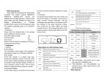
MC-Mini Chassis 1U 12-Slots Mini Media Converter 19” Rack Mount Chassis User Manual 1 Copy Please contact the dealer immediately for any loss or damage to the above items. Installation 1. Install the hanging ears on the media converters. The hanging ear is designed to be installed on the left rear side of the media converter with two screws. 2. Install the media converters in the chassis in sequence. We suggest to first install the lower level media converters (up to six), then install the upper level media converters (up to six). Each media converter can be fixed tightly in the chassis by one screw. 3. Install the chassis onto the standard 19-inch rack (if there is a rack). 4. Connect the CAT5e or CAT6 twisted-pair and Fiber cables to other network devices. Then connect the power cords and turn on the power switch, the installed media converters will work. The corresponding LED is ON for correct connection. Ordering Information MC-Mini-AD One AC100-240V one DC48V power supplies MC-Mini-AA Dual AC100-240V power supplies MC-Mini-DD Dual DC48V power supplies Packing list Please check the following items in the package before installing the 1U height rack mount chassis. MC-Mini Chassis AC Power Cords Metal screws and hanging ears 1 Unit 1 or 2 PCS 1 small bag 2. Environmental Conditions: - Operating temperature range: 0℃ to 50℃ - Cooling mode: brushless DC fan - Storage temperature range: -20℃ to +70℃ - Operating Humidity range: 90% max, non-condensing 3. Mechanical Specifications: - Case Material: Iron - Case Color: Black - Net Weight: 3.2Kg approx. / unit - Dimensions: 485 (W) x 270 (D) x 44.5 (H) (mm) 4. LED indicators: -PWR: power supply (red) -FAN: cooling FAN (green) User Manual Brief introduction This rack mount chassis is specially designed for accommodating chassis-based mini Media Converters. It is a standard 19 inch 1U height rack mount chassis which can be mounted in the standard 19-inch rack. The chassis lets you install multiple mini media converters in an equipment rack together with the network devices. This is space saving and neat look cabling. The chassis works with its own universal AC/DC or AC/AC or DC/DC power supplies. For maximum power availability, the configuration of active/stand-by power supply ensures uninterruptible operation of the system. This product is suitable for standard 19 inch network rack. Technical parameters: 1. Power Requirements: - Input Power: AC 100-240V 50/60Hz or/and DC36-72V (48V typical) - Output Power: DC12V - Power Output: 36 Watts maximum Front side view Rear side view Descriptions of LED indicators Both front and real LED indicators serve as device monitoring and trouble display. The following is the description for each LED indicator: PWR1 PWR2 FAN1 FAN2 ON: Power 1 is OK OFF: No Power or Power 1 is failed ON: Power 2 is OK OFF: No Power or Power 2 is failed ON: Fan in Power 1 is OK and working OFF: No Power or FAN in Power 1 is failed ON: Fan in Power 2 is OK and working OFF: No Power or FAN in Power 2 is failed Main features 1. Suitable for standard 19 inch network rack. 2. 1U height, maximum 12 slots capacity. 3. Supports several module type media converters. 4. Supports redundant power supplies. 5. Supports hot-swappable operation. 6. Two side LED indicators (front and rear). Cautions: 1. This product is suitable for indoor applications. 2. Put it under a dust cover when not in use. 3. It is forbidden to stare at the TX fiber-transfer end with naked eyes. 4. WDM transceivers must be used in pair. Trouble shooting: 1. Device is not matched. Please select the corresponding network device according to the transfer rate of the product when connected to other network devices. 2. Line loss is excessive during the fiber wiring. Excessive loss in connector plug-in and fiber soldering, and excessive intermediate nodes may cause excessive loss rate or abnormal operation.
