1
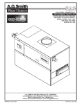
3/4” PIPE CLAMP WITH STAND
Model 94053
ASSEMBLY AND OPERATING INSTRUCTIONS
(3/4” DIAMETER PIPE NOT INCLUDED.)
®
3491 Mission Oaks Blvd., Camarillo, CA 93011
Visit our Web site at: http://www.harborfreight.com
TO PREVENT SERIOUS INJURY,
READ AND UNDERSTAND ALL WARNINGS
AND INSTRUCTIONS BEFORE USE.
Copyright© 2005 by Harbor Freight Tools®. All rights reserved. No portion of this
manual or any artwork contained herein may be reproduced in any shape or form
without the express written consent of Harbor Freight Tools.
For technical questions or replacement parts, please call 1-800-444-3353.
PRODUCT SPECIFICATIONS
Item
Product Compatibility
Clamping Mechanism
Adjusting Screw Housing Dimensions
Lead Screw Dimensions
Lead Screw Thread Type
Crank Handle Dimensions
Throat Depth
Sliding Jaw Dimensions
Additional Features
Unit Weight
Note:
Description
Fits all 3/4” NPT metal pipes (not included)
Four disc clutch for heavy duty clamping
From 5/8” to 1-1/2” W x 3-3/4” H x 3/4” L
4-5/8” L x .604” Outside Diameter
Acme threads
From 9/16” to 1-7/8” L x 1/4” to 7/8” W x 4” H
1-11/16”
From 1-5/8” to 2-3/8” L x 1/4” to 2” W x 3-1/8” to 4-1/2” H
Adjusting Screw Housing Base and Sliding Jaw Base
each provide two 7/32” mounting holes to attach wooden
pads (not included) to protect workpiece.
Design allows for Hand Crank to turn without touching
workbench.
2.70 Pounds
No replacement parts are available for this product
UNPACKING
When unpacking, check to make sure all the parts shown on page 4 are included. If any
parts are missing or broken, please call Harbor Freight Tools at the number shown on the
cover of this manual as soon as possible.
SAVE THIS MANUAL
You will need this manual for the safety warnings and precautions, assembly, operating,
inspection, maintenance and cleaning procedures, parts list and assembly diagram.
Keep your invoice with this manual. Write the invoice number on the inside of the front
cover. Keep this manual and invoice in a safe and dry place for future reference.
WARNING!
READ AND UNDERSTAND ALL INSTRUCTIONS
Failure to follow all instructions listed in the following
pages may result in electric shock, fire, and/or serious injury.
SAVE THESE INSTRUCTIONS
SKU 94053
For technical questions please call 1-800-444-3353
PAGE 2
GENERAL SAFETY PRECAUTIONS
1.
Maintain the label on the Pipe Clamp. This carries important information. If
unreadable or missing, contact Harbor Freight Tools for a replacement.
2.
The Pipe Clamp is designed to work with all 3/4” NPT metal pipes (not
included). Do not attempt to subsitute a 3/4” NPT pipe with any other size or
type of pipe or any other object.
3.
Stay alert. Watch what you are doing, and use common sense when
operating this product. Do not use this product while tired or under the
influence of drugs, alcohol, or medication. A moment of inattention while
operating this product may result in serious personal injury.
4.
Store this product out of reach of children and other untrained persons.
Tools and equipment are dangerous in the hands of untrained users. Do not let
children handle or play with this product.
5.
Maintain this product with care. Do not use this product if damaged. If
damaged, tag this product “Do not use” until repaired.
6.
Use the right product for the job. Do not attempt to force a small tool or
accessory to do the work of a larger industrial tool or accessory. There are certain
applications for which this product was designed. It will do the job better and
more safely at the rate for which it was intended. Do not modify this product,
and do not use this product for a purpose for which it was not intended.
7.
Always release tension on the Pipe Clamp and remove any workpieces
from the tool before performing maintenance or cleaning procedures.
8.
Repair service must be performed only by qualified repair personnel.
Service or maintenance performed by unqualified personnel could result in a risk
of injury.
9.
Always wear ANSI approved safety impact eye goggles when assembling
and operating this product.
10.
WARNING! The warnings, precautions, and instructions discussed in this
manual cannot cover all possible conditions and situations that may occur. The
operator must understand that common sense and caution are factors, which
cannot be built into this product, but must be supplied by the operator.
SKU 94053
For technical questions please call 1-800-444-3353
PAGE 3
ASSEMBLY AND OPERATING INSTRUCTIONS
To Attach Protective Wood Pads To The Pipe Clamp:
1.
The Adjusting Screw Housing (1) and Sliding Jaw Housing (2) each are
constructed of steel, and when tightened against the edges of a wooden
workpiece may scratch or dent the workpiece. Therefore, it is recommended that
in order to better protect the surface of the workpiece a wooden pad (not
included) be attached to both the Adjusting Screw Housing and Sliding Jaw
Housing.
2.
To construct a wooden pad for the Adjusting Screw Housing (1) and Sliding Jaw
Housing (2), cut two 1/2” thick pieces of a soft wood (i.e., fir or pine) to 1-7/8”
wide by 1-5/8” long. (See Figure A.)
3.
Place the wooden pads against the Adjusting Screw Housing (1) and Sliding Jaw
Housing (2), and use the two 7/32” diameter mounting holes in each Housing as
a template to mark the locations where two 7/32” diameter holes will be drilled in
each wooden pad. (See Figure A.)
4.
Drill the two 7/32” diameter holes in each of the wooden pads. Make sure to
countersink the holes in order to recess the head of the bolts (not included) that
will be used to secure the wooden pads to the Adjusting Screw Housing (1) and
Sliding Jaw Housing (2). (See Figure A.)
5.
Use two 3/4”-1” long by 7/32” diameter Bolts with Lockwashers and Nuts to
secure a wooden pad to the Adjusting Screw Housing (1). Repeat this Step for
the Sliding Jaw Housing (2). (See Figure A.)
WOODEN PAD
1/2”
(NOT INCLUDED)
FIGURE A
7/32” HOLE
(COUNTERSINK)
1-5/8”
WOODEN PAD
(NOT INCLUDED)
NUT/WASHER
1-7/8”
BOLT (NOT INCLUDED)
(NOT INCLUDED)
DISC CLUTCH (3)
LEG
SKU 94053
HAND
CRANK (4)
ADJUSTING SCREW HOUSING (1)
SLIDING JAW HOUSING (2)
3/4” NPT PIPE (NOT INCLUDED)
For technical questions please call 1-800-444-3353
LEG
PAGE 4
To Assemble The Pipe Clamp:
1.
Screw the threaded end of a 3/4” NPT Pipe (not included) firmly into the Adjusting
Screw Housing (1). (See Figure A.)
2.
Push in on the Disc Clutch (3) of the Sliding Jaw Housing (2), and insert the
Sliding Jaw Housing onto the 3/4” NPT Pipe. Then, release pressure on the Disc
Clutch to lock the Sliding Jaw Housing in place. (See Figure A.)
To Operate The Pipe Clamp:
1.
Set the assembled Pipe Clamp on a flat, level, sturdy workbench capable of
supporting the weight of the Pipe Clamp, additional tools, and workpieces. Make
sure to position the Pipe Clamp on its “legs” in order to elevate the Pipe Clamp
and allow the Hand Crank (4) to be turned freely. (See Figure A.)
2.
Open the Hand Crank (4) by turning it counterclockwise. (See Figure A.)
3.
Push in on the Disc Clutch (3) of the Sliding Jaw Housing (2), and slide the
Sliding Jaw Housing toward the end of the 3/4” NPT Pipe. Then, release
pressure on the Disc Clutch to lock the Sliding Jaw Housing in place.
(See Figure A.)
4.
Place the workpiece(s) between the Adjusting Screw Housing (1) and Sliding Jaw
Housing (2), allowing the workpiece(s) to rest on the 3/4” NPT Pipe. Then, slide
the workpiece(s) to the right so that its right edge is against the Adjusting Screw
Housing. (See Figure A.)
5.
Push in on the Disc Clutch (3) of the Sliding Jaw Housing (2), and slide the
Sliding Jaw Housing to the left edge of the workpiece(s). Then, release pressure
on the Disc Clutch to lock the Sliding Jaw Housing in place. (See Figure A.)
6.
Slowly turn the Hand Crank (4) clockwise to apply pressure on the workpiece(s).
Apply only enough pressure to hold the workpiece(s) firmly in place. Too much
pressure may buckle the workpiece(s) or cause it to split. (See Figure A.)
7.
When finished using the Pipe Clamp, slowly turn the Hand Crank (4) counterclockwise to release pressure on the workpiece(s). Push in on the Disc Clutch
(3) of the Sliding Jaw Housing (2), and slide the Sliding Jaw Housing toward the
end of the 3/4” NPT Pipe. Then, remove the workpiece(s) from the Pipe Clamp.
(See Figure A.)
8.
Make sure to store the Pipe Clamp in a safe, clean, dry, location out of reach of
children and other unauthorized users.
SKU 94053
For technical questions please call 1-800-444-3353
PAGE 5
INSPECTION, MAINTENANCE, AND CLEANING
1.
Before each use, inspect the general condition of the Pipe Clamp. Check for
broken, cracked, or bent parts, loose or missing parts, and any condition that
may affect the proper operation of the product. If a problem occurs, have the
problem corrected before further use.
Do not use damaged tools.
2.
After each use, clean the Pipe Clamp with a soft cloth and mild detergent. Do
not use solvents.
3.
When storing, make sure to store the Pipe Clamp in a safe, dry, clean location
out of reach of children and untrained users.
NOTE:
No replacement parts are available for this product.
PLEASE READ THE FOLLOWING CAREFULLY
THE MANUFACTURER AND/OR DISTRIBUTOR HAS PROVIDED THE PARTS LIST AND ASSEMBLY
DIAGRAM IN THIS MANUAL AS A REFERENCE TOOL ONLY. NEITHER THE MANUFACTURER OR
DISTRIBUTOR MAKES ANY REPRESENTATION OR WARRANTY OF ANY KIND TO THE BUYER THAT
HE OR SHE IS QUALIFIED TO MAKE ANY REPAIRS TO THE PRODUCT, OR THAT HE OR SHE IS
QUALIFIED TO REPLACE ANY PARTS OF THE PRODUCT. IN FACT, THE MANUFACTURER AND/OR
DISTRIBUTOR EXPRESSLY STATES THAT ALL REPAIRS AND PARTS REPLACEMENTS SHOULD BE
UNDERTAKEN BY CERTIFIED AND LICENSED TECHNICIANS, AND NOT BY THE BUYER. THE BUYER
ASSUMES ALL RISK AND LIABILITY ARISING OUT OF HIS OR HER REPAIRS TO THE ORIGINAL
PRODUCT OR REPLACEMENT PARTS THERETO, OR ARISING OUT OF HIS OR HER INSTALLATION
OF REPLACEMENT PARTS THERETO.
SKU 94053
For technical questions please call 1-800-444-3353
PAGE 6